

Page 1
Communication Protocol
RS232C
Serial Interface
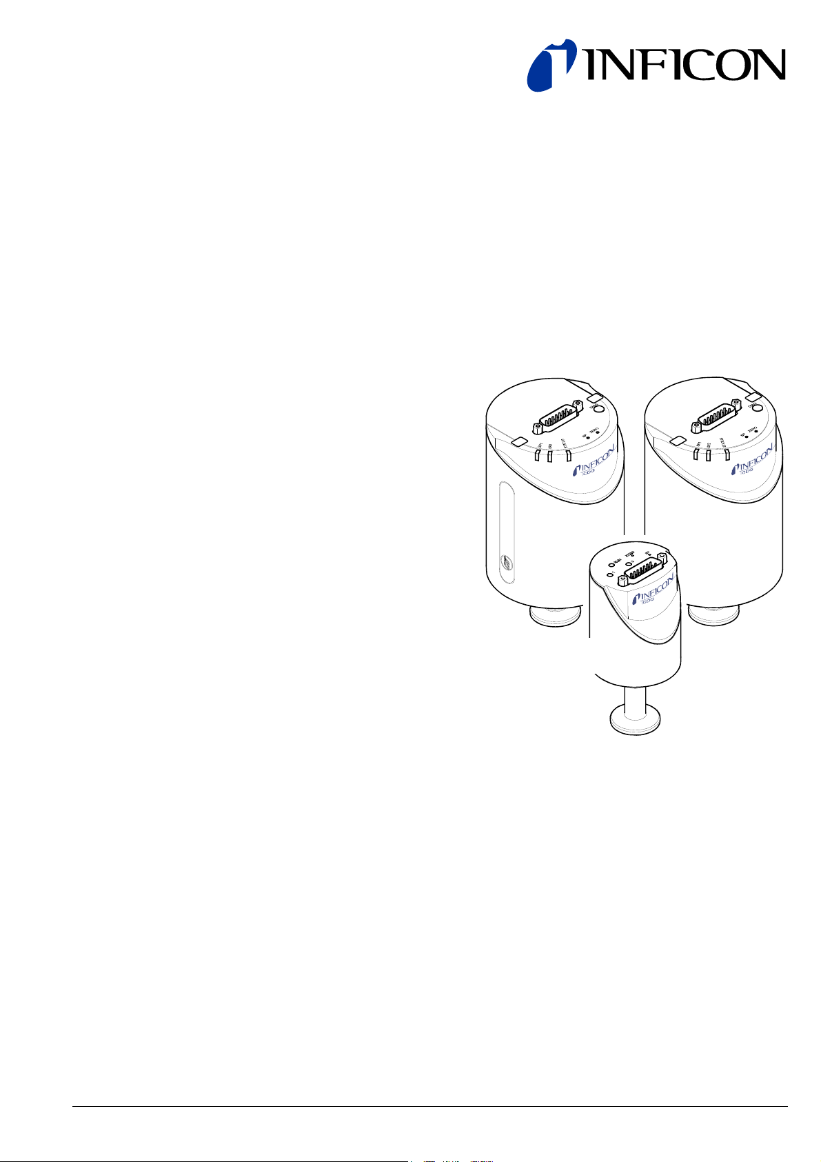
CDG025D, CDG045D,
CDG100D, CDG160D,
CDG200D
RS232C
tira49e1-a (2010-02) 1
Page 2
General Information
The RS232C Serial Interface permits the communication between the digital
INFICON Capacitance Diaphragm Gauge and
• an INFICON Vacuum Gauge Controller (VGC series) or
• another appropriate controller.
The RS232C Serial Interface integrated in the Capacitance Diaphragm Gauge
allows to digitally transmit measurement values and information on the gauge
status as well as to make parameter settings.
Functional Principle
Data format
Transmission rate
Pin assignment
Caution
Caution: data transmission errors
Any attempt to simultaneously operate the gauge via the RS232C
Serial Interface and a fieldbus interface (DeviceNet or Profibus) or the
diagnostic port may result in incorrect data and data transmission
errors.
Therefore, it is inadmissible to simultaneously operate the gauge via
the RS232C Serial Interface and DeviceNet, Profibus, or the
The RS232C Serial Interface is used in duplex operation. The gauge continuously
(approximately every 20 ms) transmits a nine byte send string without request.
Instructions to the gauge are transmitted via five-byte receipt strings.
• binary
• 8 data bits
• 1 stop bit
• no parity bit
• no handshake
• 9600 Baud
• TxD Pin 13
• RxD Pin 14
• GND Pin 5
(sensor cable connector)
diagnostic port.
2
tira49e1-a (2010-02) RS232C.cp
Page 3
1 Interface Protocol
1.1 Send String
Structure of send string
Status byte
(byte No. 2)
The complete send string (frame) is nine bytes (byte 0 … 8) long. Bytes 1 … 7 form
the data string.
Byte No. Function Value Comment
0 Data string length 7 Constant value
1 Page No. 4
2 Status
3 Error
4 Measured value high byte <value>
5 Measured value low byte <value>
Constant value for CDG025D1)
3
Constant value for CDGxxxD
2
Constant value for CDG025D 3)
→ "Status byte"
→ "Error byte"
→ "Calculation of pressure value"
→ "Calculation of pressure value"
2)
6 Read command <value> Read value
7 Sensor type
8 Checksum
1)
CDG025D with output signal 10.00 V (analog)
2)
CDG045D, CDG100D, CDG160D, CDG200D with output signal 10.24 V (analog)
3)
CDG025D with output signal 10.24 V (analog)
→ "Sensor type"
→ "Synchronization"
Bit 0 Definition
0 Continuous output of measured value
1 Individual measured value (polling) 1)
1)
→ 8, "DataTxMode". Send a read command of any parameter to the gauge for
requesting a send string.
Bit 2 Bit 1 Definition
1 0 Manual setpoint setting
1 1 Zero adjust active
Bit 3 Definition
0 ⇔ 1
Toggle bit, changes with every string
received correctly
Bit 5 Bit 4 Definition
0 0 Current pressure unit mbar
0 1 Current pressure unit Torr
1 0 Current pressure unit Pa
Bit 6 Definition
0 Standard measurement mode
1 Reserved for internal use
Bit 7 Definition
0 Heating
1)
1 Sensor temperature attained 1)
1)
for CDG045D, CDG100D, CDG160D, CDG200D only
tira49e1-a (2010-02) RS232C.cp 3
Page 4

Error byte
(byte No. 3)
Error handling
Calculation of pressure value
Conversion formula
(byte No. 4 and 5)
Bit No. Definition
0 RS232 synchronization error
1 Incorrect command, e.g. inadmissible address (syntax error)
2 Inadmissible read command
3 SP1 status
4 SP2 status
5 Not used
6 Not used
7
Extended error set (→ Read command "Extended Error
L-Byte and H-Byte")
No bit set → value = 0x00 = no error set
Errors are only recorded in the error bytes as long as they persist, except for
RS232 interface errors. Errors are not acknowledged.
RS232 errors are signaled by the "toggle bit", i.e. when an RS232 error occurs, the
"toggle bit" is not inverted. For checking the status of the "toggle bit", a read
operation is required, which also allows to read the error byte for detailed error
analysis.
If an "extended error" is set, it has to be read as variable by means of the "read
command" (→ table "Variables for bytes No. 2 and 3"). After the read operation, the
variable is automatically erased.
The pressure is calculated from bytes 4 and 5 of the send string (decimal
presentation).
<pressure_value>×a
p =
b
×F.S.R._Mantissa×10
(F.S.R._Exp)
Parameter Description
p
Pressure value in selected pressure unit (→ Parameter a)
<pressure_value> Pressure measurement data, composed of "low and high
byte" (16 bit value) and converted into decimal format
F.S.R._Mantissa F.S.R. factor according to "Sensor type" variable, which
has to be read separately (→ "Read command")
F.S.R._Exp F.S.R. exponent according to "Sensor type" variable, which
has to be read separately (→ "Read command")
a Conversion factor for pressure units other than "Torr".
Torr: a = 1.00
mbar: a = 1.3332
Pa: a = 133.32
b Factor for resolution
Page No. 1) b Output signal
2 32000 10.24 V
3 32000 10.24 V
4 32767 10.00 V
1)
→ 3, tabel "Structure of send string", byte no. 1
4
tira49e1-a (2010-02) RS232C.cp
Page 5

Read command
(byte No. 6)
Sensor type
(byte No. 7)
Checksum and synchronization
(byte No. 8)
All variables in a receipt string that are addressed for reading are output on this
byte. For variable types >1 byte, each byte (e.g. low, high, or further bytes) has to
be addressed and read individually.
Read Command L-Byte → Read Data L-Byte
Read Command H-Byte → Read Data H-Byte
• After a write operation, the value of the addressed variable is output.
• After a reset (Power on) the software version is output on byte 6.
Bit No.
Description Comment
0 … 3
0x0 F.S.R.= 10-3
→ Variable "Sensor_pressure_range"
0x1 F.S.R.= 10-2 F.S.R._Exponent = (<value> -3)
0x2 F.S.R.= 10-1
0x3 F.S.R.= 100 = 1
0x4 F.S.R.= 101 = 10
0x5 F.S.R.= 102 = 100
0x6 F.S.R.= 103 = 1000
0x7 F.S.R.= 104 = 10000
Bit No.
Description Comment
4 … 7
0x0 F.S.R._Mantissa = 1.0
→ Variable "Sensor_FSR"
0x1 F.S.R._Mantissa = 1.1
0x2 F.S.R._Mantissa = 2.0
0x3 F.S.R._Mantissa = 2.5
0x4 F.S.R._Mantissa= 5.0
The recipient (master) is synchronized by checking three bytes:
Byte No. Function Value Comment
0 Data string length 7 Constant value
1 Page No. 4
3
2
8 Checksum of bytes
0 … 255 Low byte of checksum 4)
Constant value for CDG025D
Constant value for CDGxxxD
Constant value for CDG025D 3)
1)
2)
No. 1 … 7
1)
CDG025D with output signal 10.00 V (analog)
2)
CDG045D, CDG100D, CDG160D, CDG200D with output signal 10.24 V (analog)
3)
CDG025D with output signal 10.24 V (analog)
4)
Possible high bytes are ignored
tira49e1-a (2010-02) RS232C.cp 5
Page 6

Example
1.2 Receipt String
Structure of receipt string
The example is based on the following output string:
Byte No. 0 1 2 3 4 5 6 7 8
Value 7 2 16 0 125 0 20 6 69
The instrument or controller (receiver) interprets this string as follows:
Byte No. Function Value Comment
0 Length of
7 (Set value)
datastring
1 Page No. 2 CDG025D with output signal 10.24 V
2 Status 16 Pressure unit = Torr
3 Error 0 No Error
4
5
Measurement
High byte
Low byte
Calculation of pressure value: Conversion
125
formula → 4
0
6 Read command 20 Software version = 20 / 20 = 1.0
7 Sensor type 6 F.S.R.= 10+3
8 Check sum 169 2 + 16 + 0 + 125 + 0 + 20 + 6 =
169
≙ 00 A9
dec
hex
High order byte is ignored ⇒
Check sum = A9
hex
≙ 169
dec
Commands to the gauge are transmitted in receipt strings (frames) consisting of
five bytes (without <CR>). The data string is formed by bytes 1 … 3.
Byte No. Designation Value
0 Data string length 3 (constant value)
1 Data
2 Data
3 Data
4 Checksum
1)
Possible high bytes are ignored.
of bytes No. 1 … 3
<value>
→ "Service command"
→ "Address byte"
→ "Data byte"
Low byte of checksum 1)
• The operation selected in byte No. 1 is addressed in byte No. 2.
• Variables are transmitted in byte No. 3. Variables >1 byte have to be
transmitted in several receipt strings (splitting).
6
tira49e1-a (2010-02) RS232C.cp
Page 7

Service command
(byte No. 1)
Address byte
(byte No. 2)
Data byte
(byte No. 3)
Checksum
(byte No. 4)
Example
Description Data Comment
Read command 0x00 Read command for variable according to
address in byte No. 2
Write command 0x10 Write command for variable according to
address in byte No. 2
Special services 0x40 Direct command (write command) without
data information, e.g. Reset, Zero adjust
Enter the address of the variable to be read/written (→ table "Variables for bytes
No. 2 and 3").
When a variable is written (receipt string) the content of byte No. 3 is written to the
variable addressed in byte No. 2 (→ table "Variables for bytes No. 2 and 3").
When a variable is read (send string), the value of the variable addressed in byte
No. 2 is output in byte No. 6 of the send string. The content of byte No. 3 is not
relevant for read operations.
The checksum is calculated from the sum of byte No. 1 to 3.
Das Beispiel basiert auf dem Empfangsstring:
Byte No. 0 1 2 3 4
Value 3 0 2 0 2
The instrument or controller (receiver) interprets this string as follows:
Byte No. Designation Value Comment
0 Data string
3 (constant value)
length
1 Service
0 Read command
command
2 Address byte 2 Filter
3 Data byte 0
4 Checksum 2
0 + 2 + 0 = 2
≙ 00 02
dec
hex
High bytes are ignored ⇒
Checksum = 02
hex
≙ 2
dec
tira49e1-a (2010-02) RS232C.cp 7
Page 8

Variables for bytes No. 2 and 3
(read/write command)
Parameter name Data type Description Byte No. 2 Byte No. 3 Comment
DataTxMode uint8_T / RW 0 0 1) Continued output of measured value
1 Individual output of measured value
(polling)
Unit uint8_T / RW 1 0 Pressure unit "mbar"
1
1)
Pressure unit "Torr"
Filter uint8_T / RW 2 0 1) Filter dynamic
1 Filter time fast
2 Filter time slow
SP1 Level Low sint16_T / RW H-Byte 4 <value> Lower setpoint threshold SP1 2)
L-Byte 5 <value>
SP2 Level Low sint16_T / RW H-Byte 6 <value> Lower setpoint threshold SP2 2)
L-Byte 7 <value>
SP1 Level High sint16_T / RW H-Byte 8 <value> Upper setpoint threshold SP1
(hysteresis)
2)
L-Byte 9 <value>
SP2 Level High sint16_T / RW H-Byte 10 <value> Upper setpoint threshold SP2
(hysteresis)
2)
L-Byte 11 <value>
Software version uint8_T / Ro 16 <value> (<value> / 20) = Software Version
e.g. 20 = V1.0
Calib date uint32_T / Ro MSB 17 <value> Date: YY,MM,DD,HH,MM
Byte 2 18 <value> e.g. 0410291109 =
Byte 1 19 <value> 2004-10-29 at 11:09
LSB 20 <value>
Zero_Adjust_Value sint16_T / RW H-Byte 21 <value> Zero Offset Adjust Level 3)
L-Byte 22 <value>
DC Output Offset sint16_T / RW H-Byte 23 <value> Customer DC Output Offset 3)
L-Byte 24 <value> (Base pressure offset)
Production No. uint8_T / Ro Byte 0 25 <value> Production number as ASCII string
(barcode)
uint8_T / Ro Byte 1 26 <value> (Max. 16 byte)
uint8_T / Ro … … ...
uint8_T / Ro Byte 15 40 <value> (Last digit: null terminator)
Software date Year uint16_T / Ro H-Byte 212 <value> Software version date Year in Hex
e.g. 0x2007 = 2007
L-Byte 213 <value>
Software date M/D Uint16_T / Ro H-Byte 214 <value> Software version date Month in Hex
e.g. 0x03 = March
L-Byte 215 <value> Software version date Day in Hex
e.g. 0x19 = 19
Part No. uint8_T / Ro Byte 0 218 <value> Part number as ASCII string
uint8_T / Ro Byte 1 219 <value> (Max 20 byte)
uint8_T / Ro … … <value> e.g. 378-000
uint8_T / Ro Byte 19 237 <value> (Last digit: null terminator)
Remaining_Zero sint16_T / Ro H-Byte 72 <value> Max. remaining offset value
L-Byte 73 <value>
(continued)
8
tira49e1-a (2010-02) RS232C.cp
Page 9

(completed)
Parameter name Data type Description Byte No. 2 Byte No. 3 Comment
Extended error uint8_T / Ro H-Byte 54 Bit 0 PT1000 fault 4)
H-Byte
Bit 1 Heater block overtemp.
4)
Bit 2 Electronic overtemp. 4)
Bit 3 Zero adjust error
Bit 4 Reserve
Bit 5 Reserve
Bit 6 Reserve
Bit 7 Reserve
Extended error uint8_T / Ro L-Byte 55 Bit 0 Atm. pressure out of range
L-Byte
Bit 1 Temperature out of range
Bit 2 Reserve
Bit 3 Reserve
Bit 4 Cal. mode wrong
Bit 5 Pressure underflow
Bit 6 Pressure overflow
Bit 7 Zero adjust warning
Pressure range uint8_T / Ro 56 0 F.S.R. = E-3
(Exponent)
1 F.S.R. = E-2
2 F.S.R. = E-1
3 F.S.R. = E 0
4 F.S.R. = E+1
5 F.S.R. = E+2
6 F.S.R. = E+3
7 F.S.R. = E+4
Pressure range uint8_T / Ro 57 0 Mantissa = 1.0
(Mantissa)
1 Mantissa = 1.1
2 Mantissa = 2.0
3 Mantissa = 2.5
4 Mantissa = 5.0
Gauge config uint8_T / Ro 58 0 = Analog out 0 … 10.24 V
1 = Analog out 1 … 9 V
CDG type uint8_T / Ro 59 0 = CDG025D
1 = CDG045D
2 = CDG100D
3 = CDG160D
4 = CDG200D
RW = Read / Write Ro = Read only
1)
Factory setting
2)
Conversion → Section 1.1, byte 6 "Read command"
3)
Conversion → Section 1.1, bytes 4 and 5 "Pressure unit"
4)
CDG045D, CDG100D, CDG160D, CDG200D only
tira49e1-a (2010-02) RS232C.cp 9
Page 10

Variables for bytes No. 2 and 3
(special services)
Parameter name Data type Description Byte No. 2 Byte No. 3 Comment
RESET uint8_T / W 0 0 Power reset: Starts continuous
pressure output
RESET Factory uint8_T / W 1 0 Factory reset: Sets factory confi-
guration
Zero_adjust uint8_T / W 2 – Starts zero offset adjustment
W = Write
Description of variables
Setpoint_level xy
Setpoint_level xy =
<data_value>×a
b
× F.S.R._Mantisse×10
(F.S.R._Exp)
1)
Parameter
Description
Setpoint_level xy Setpoint threshold in the selected pressure unit.
1)
Further parameter → 11, table "Parameter"
• Minimum value lower switching threshold = 0 ; negative values are not
admissible.
• Maximum value lower switching threshold = F.S.R. – 1 % hysteresis.
Zero_Adjust_Value
Zero_Adjust_Value contains the zero pressure offset value required for zeroing
(writable and readable).
• Automatic zero_adjust function via key or command (→ table "Variables for
bytes No. 2 and 3 (special services)").
• Base-Pressure-Adjust for adjusting a defined zero offset, e.g. if the required
final pressure as indicated in the operating manual is not reached.
The Zero_Adjust_Value consists of the high and low byte and has to be converted
with the "Pressure value" formula (→ 4).
Zero_Adjust_Value =
<data_value>×a
b
×F.S.R._Mantisse×10
(F.S.R._Exp)
1)
Parameter
Description
Zero_Adjust_Value Zero pressure offset in the selected pressure unit
(→ 11, table "Parameter").
1)
Further parameter → 11, table "Parameter"
Remaining_Zero
Maximal remaining offset value. The Zero_Adjust can only be executed within this
value.
10
tira49e1-a (2010-02) RS232C.cp
Page 11

DC Output Level
Software version
Parameter
The "DC Output Level" variable is used for assigning a defined offset level to the
analog output signal, e.g. for setting a certain zero offset signal level.
A "DC Output Level" >0 reduces the output range of the measurement
range 0 … 10 V by the selected offset value (F.S.R. - DC output level).
The "DC Output Level" parameter (16-Bit) consists of the high and low byte.
DC Output Level =
<data_value>×a
b
×F.S.R._Mantisse×10
(F.S.R._Exp)
Parameter
1)
Description
DC Output Level DC-Output-Signal in the selected pressure unit
(→ 11, table "Parameter").
1)
Further parameter → 11, table "Parameter"
Software version =
<data_value>
20
e.g. <data_value> = 20 ≙ V1.0
Parameter Description
<data_value> 1 byte value (8 bit), data value in decimal format.
Parameter Description
<data_value> Zero offset measurement data, consisting of "low and high
byte" (16 bit value), data value in decimal format.
a Conversion factor for pressure units other than "Torr"
Torr: a = 1.00
mbar: a = 1.3332
Pa: a = 133.32
b Factor for resolution
Page No. 1) b Output signal
2 32000 10.24 V
3 32000 10.24 V
4 32767 10.00 V
F.S.R._Mantisse F.S.R. factor according to the "Sensor type" variable, which
has to be read separately (→ "Read command").
F.S.R._Exp F.S.R. exponent according to "Sensor type" variable, which
has to be read separately (→ "Read command").
1)
→ 3, tabel "Structure of send string", byte no. 1
tira49e1-a (2010-02) RS232C.cp 11
Page 12

LI–9496 Balzers
Liechtenstein
Tel +423 / 388 3111
Fax +423 / 388 3700
Original: German tira49d1-a (2010-02) reachus@inficon.com
t i r a49e1- a
www.inficon.com
 Loading...