

Page 1
OPERATING MANUAL
RSH-600
Rotary Sensor Head
IPN 153800-G
Page 2

Page 3

www.inficon.com reachus@inficon.com
©2012 INFICON
®
OPERATING MANUAL
RSH-600
Rotary Sensor Head
IPN 153800-G
Page 4

Trademarks
The trademarks of the products mentioned in this manual are held by the companies that
produce them.
Scotch-Brite® is a registered trademark of 3M.
Teflon® is a registered trademarks of E. I. du Pont de Nemours and Company or its affiliates.
Windows® and Microsoft® are registered trademarks of Microsoft Corporation.
All other brand and product names are trademarks or registered trademarks of their respective companies.
Disclaimer
The information contained in this manual is believed to be accurate and reliable. However, INFICON assumes
no responsibility for its use and shall not be liable for any special, incidental, or consequential damages related
to the use of this product.
Due to our continuing program of product improvements, specifications are subject to change without notice.
Copyright
©2012 All rights reserved.
Reproduction or adaptation of any part of this document without permission is unlawful.
Page 5

Warranty
WARRANTY AND LIABILITY - LIMITATION: Seller warrants the products
manufactured by it, or by an affiliated company and sold by it, and described on
the reverse hereof, to be, for the period of warranty coverage specified below, free
from defects of materials or workmanship under normal proper use and service.
The period of warranty coverage is specified for the respective products in the
respective Seller instruction manuals for those products but shall not be less than
one (1) year from the date of shipment thereof by Seller. Seller's liability under this
warranty is limited to such of the above products or parts thereof as are returned,
transportation prepaid, to Seller's plant, not later than thirty (30) days after the
expiration of the period of warranty coverage in respect thereof and are found by
Seller's examination to have failed to function properly because of defective
workmanship or materials and not because of improper installation or misuse and
is limited to, at Seller's election, either (a) repairing and returning the product or
part thereof, or (b) furnishing a replacement product or part thereof, transportation
prepaid by Seller in either case. In the event Buyer discovers or learns that a
product does not conform to warranty, Buyer shall immediately notify Seller in
writing of such non-conformity, specifying in reasonable detail the nature of such
non-conformity. If Seller is not provided with such written notification, Seller shall
not be liable for any further damages which could have been avoided if Seller had
been provided with immediate written notification.
THIS WARRANTY IS MADE AND ACCEPTED IN LIEU OF ALL OTHER
WARRANTIES, EXPRESS OR IMPLIED, WHETHER OF MERCHANTABILITY OR
OF FITNESS FOR A PARTICULAR PURPOSE OR OTHERWISE, AS BUYER'S
EXCLUSIVE REMEDY FOR ANY DEFECTS IN THE PRODUCTS TO BE SOLD
HEREUNDER. All other obligations and liabilities of Seller, whether in contract or
tort (including negligence) or otherwise, are expressly EXCLUDED. In no event
shall Seller be liable for any costs, expenses or damages, whether direct or
indirect, special, incidental, consequential, or other, on any claim of any defective
product, in excess of the price paid by Buyer for the product plus return
transportation charges prepaid.
No warranty is made by Seller of any Seller product which has been installed,
used or operated contrary to Seller's written instruction manual or which has been
subjected to misuse, negligence or accident or has been repaired or altered by
anyone other than Seller or which has been used in a manner or for a purpose for
which the Seller product was not designed nor against any defects due to plans or
instructions supplied to Seller by or for Buyer.
This manual is intended for private use by INFICON® Inc. and its customers.
Contact INFICON before reproducing its contents.
NOTE: These instructions do not provide for every contingency that may arise in
connection with the installation, operation or maintenance of this equipment.
Should you require further assistance, please contact INFICON.
www.inficon.com reachus@inficon.com
Page 6

Page 7

Chapter 1
1.1 Introduction. . . . . . . . . . . . . . . . . . . . . . . . . . . . . . . . . . . . . . . . . . . . . . . . . .1-1
1.2 Configurations . . . . . . . . . . . . . . . . . . . . . . . . . . . . . . . . . . . . . . . . . . . . . . . 1-2
1.3 Mounting. . . . . . . . . . . . . . . . . . . . . . . . . . . . . . . . . . . . . . . . . . . . . . . . . . . .1-2
1.4 Safety . . . . . . . . . . . . . . . . . . . . . . . . . . . . . . . . . . . . . . . . . . . . . . . . . . . . . . 1-3
1.4.1 Definition of Notes, Cautions and Warnings. . . . . . . . . . . . . . . . . . . . . . . . . 1-3
1.5 How To Contact INFICON . . . . . . . . . . . . . . . . . . . . . . . . . . . . . . . . . . . . . . 1-4
1.5.1 Returning Your Instrument . . . . . . . . . . . . . . . . . . . . . . . . . . . . . . . . . . . . . . 1-4
1.6 Specifications . . . . . . . . . . . . . . . . . . . . . . . . . . . . . . . . . . . . . . . . . . . . . . . . 1-5
1.7 Unpacking and Inspection . . . . . . . . . . . . . . . . . . . . . . . . . . . . . . . . . . . . . . 1-6
1.7.1 Base Configuration . . . . . . . . . . . . . . . . . . . . . . . . . . . . . . . . . . . . . . . . . . . . 1-6
1.8 Functional Verification . . . . . . . . . . . . . . . . . . . . . . . . . . . . . . . . . . . . . . . . .1-7
RSH-600 Operating Manual
Table Of Contents
Trademarks
Disclaimer
Copyright
Introduction
Chapter 2
Installation
2.1 Crystal Sensor Installation . . . . . . . . . . . . . . . . . . . . . . . . . . . . . . . . . . . . . . 2-1
2.2 Mounting. . . . . . . . . . . . . . . . . . . . . . . . . . . . . . . . . . . . . . . . . . . . . . . . . . . .2-2
2.3 Adjustable Flange Installation. . . . . . . . . . . . . . . . . . . . . . . . . . . . . . . . . . . .2-3
2.4 Copper Head Installation . . . . . . . . . . . . . . . . . . . . . . . . . . . . . . . . . . . . . . . 2-4
2.5 Cooling System . . . . . . . . . . . . . . . . . . . . . . . . . . . . . . . . . . . . . . . . . . . . . . 2-5
IPN 153800-G
2.6 Air Supply . . . . . . . . . . . . . . . . . . . . . . . . . . . . . . . . . . . . . . . . . . . . . . . . . . . 2-5
2.7 Crystal Position Feedback Connections. . . . . . . . . . . . . . . . . . . . . . . . . . . . 2-5
2.8 Protection from Evaporant . . . . . . . . . . . . . . . . . . . . . . . . . . . . . . . . . . . . . .2-6
Chapter 3
Troubleshooting and Maintenance
3.1 Troubleshooting . . . . . . . . . . . . . . . . . . . . . . . . . . . . . . . . . . . . . . . . . . . . . .3-1
3.2 Troubleshooting the RSH-600 . . . . . . . . . . . . . . . . . . . . . . . . . . . . . . . . . . . 3-1
3.3 Maintain the Temperature of the Crystal . . . . . . . . . . . . . . . . . . . . . . . . . . . 3-4
3.4 Use the Optimum Crystal Type . . . . . . . . . . . . . . . . . . . . . . . . . . . . . . . . . . 3-4
3.5 Crystal Concerns when Opening the Chamber . . . . . . . . . . . . . . . . . . . . . . 3-4
TOC - 1
Page 8

3.6 Crystal Holder Maintenance. . . . . . . . . . . . . . . . . . . . . . . . . . . . . . . . . . . . . 3-4
3.7 Crystal Replacement . . . . . . . . . . . . . . . . . . . . . . . . . . . . . . . . . . . . . . . . . . 3-5
Chapter 4
4.1 Accessories and Replacement Parts . . . . . . . . . . . . . . . . . . . . . . . . . . . . . . 4-1
Chapter 5
RSH-600 Operating Manual
Accessories and Replacement Parts
Outline Drawings
TOC - 2
IPN 153800-G
Page 9
1.1 Introduction
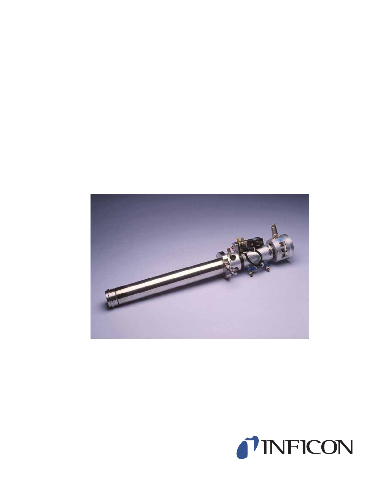
The RSH-600 rotary sensor, see Figure 1-1, is designed for the most demanding
processes employing very thick films and several different materials. Switching the
crystal without venting the system makes it possible to run automatically with
continuous deposition. The fixed position of the crystal being measured also makes
it unnecessary to change the tooling factor.
The RSH-600 can be used to deposit a different material on each of six crystals
providing greater measurement accuracy. Upon completion of deposition of one
material, the deposition controller may be programmed to switch crystals for the
next material. It may also be actuated manually.
The RSH-600 sensor holds six crystals in a thermally shielded, water cooled
housing, insuring excellent crystal performance in temperature environments up to
300ºC. Crystals are housed in an easily removable Teflon
crystal holder.
RSH-600 Operating Manual
Introduction
®
and stainless steel
Chapter 1
Crystal position is incremented by applying a one second pulse to a 110/115 V (ac)
or 24 V (dc) pneumatic valve. A 7-pin connector provides an indication of the
number of the active crystal. This may be used to interface with a thin film controller
for automatic crystal switching operation. Refer to your controller operating manual
for programming instructions.
Figure 1-1 RSH-600 and Sensor Head Options
IPN 153800-G
1 - 1
Page 10
RSH-600 Operating Manual
1.2 Configurations
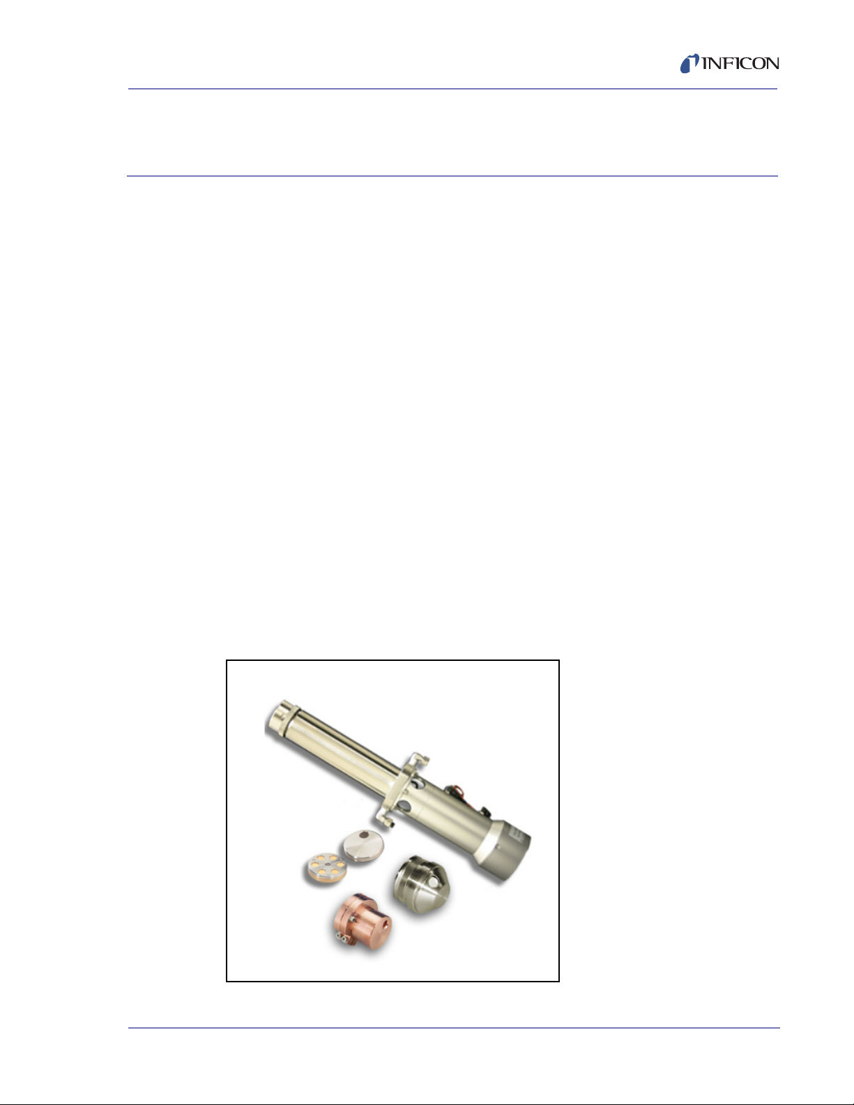
The RSH-600 can be configured with a flat head or a 45º angled head. This allows
for mounting in various locations within your vacuum chamber. Standard head
covers are made of stainless steel. Copper head covers are available for
applications where temperature is a concern (see Figure 1-2). All versions of the
RSH-600 are fixed to their specified lengths, but may be adapted to be adjustable
in length using the optional adjustable mounting flange (see Chapter 4).
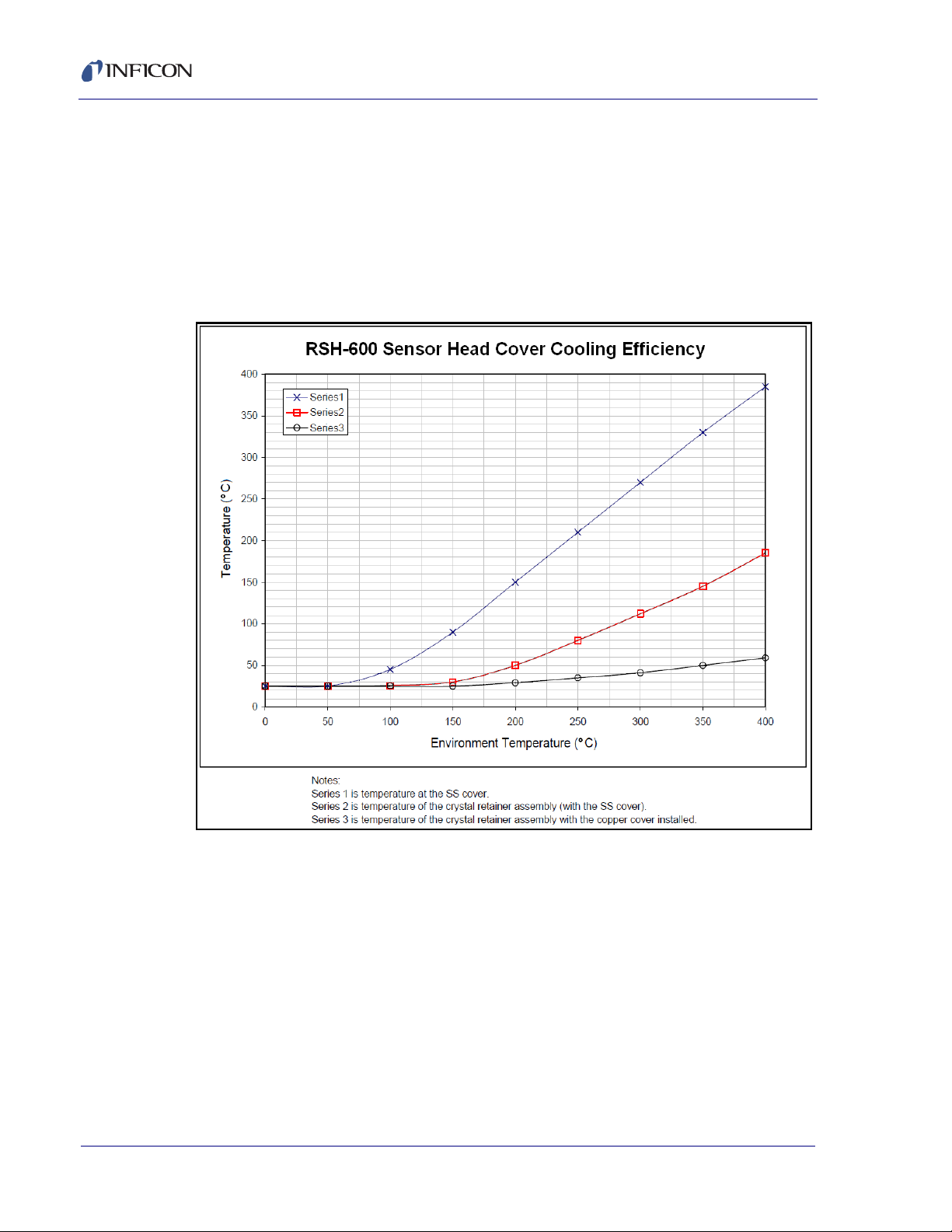
Figure 1-2 RSH-600 Sensor Head Cooling Efficiency.
1.3 Mounting
The RSH-600's smooth sealing surface mounts to an O-ring sealed nipple (not
included). The optional adjustable flange allows for the in-vacuum length to be
adjustable up to the RSH-600's original length. A flat head cover is typically used
for centered top mount applications while the angled heads may be used for either
off-center top mount or side mount applications. The customer must supply
specifications regarding mounting holes, exterior diameter of flange and the
system mating flange.
1 - 2
IPN 153800-G
Page 11
RSH-600 Operating Manual
CAUTION
WARNING
1.4 Safety
1.4.1 Definition of Notes, Cautions and Warnings
When using this manual, please pay attention to the Notes, Cautions, and
Warnings found throughout. For the purposes of this manual they are defined as
follows:
NOTE: Pertinent information that is useful in achieving maximum efficiency when
followed.
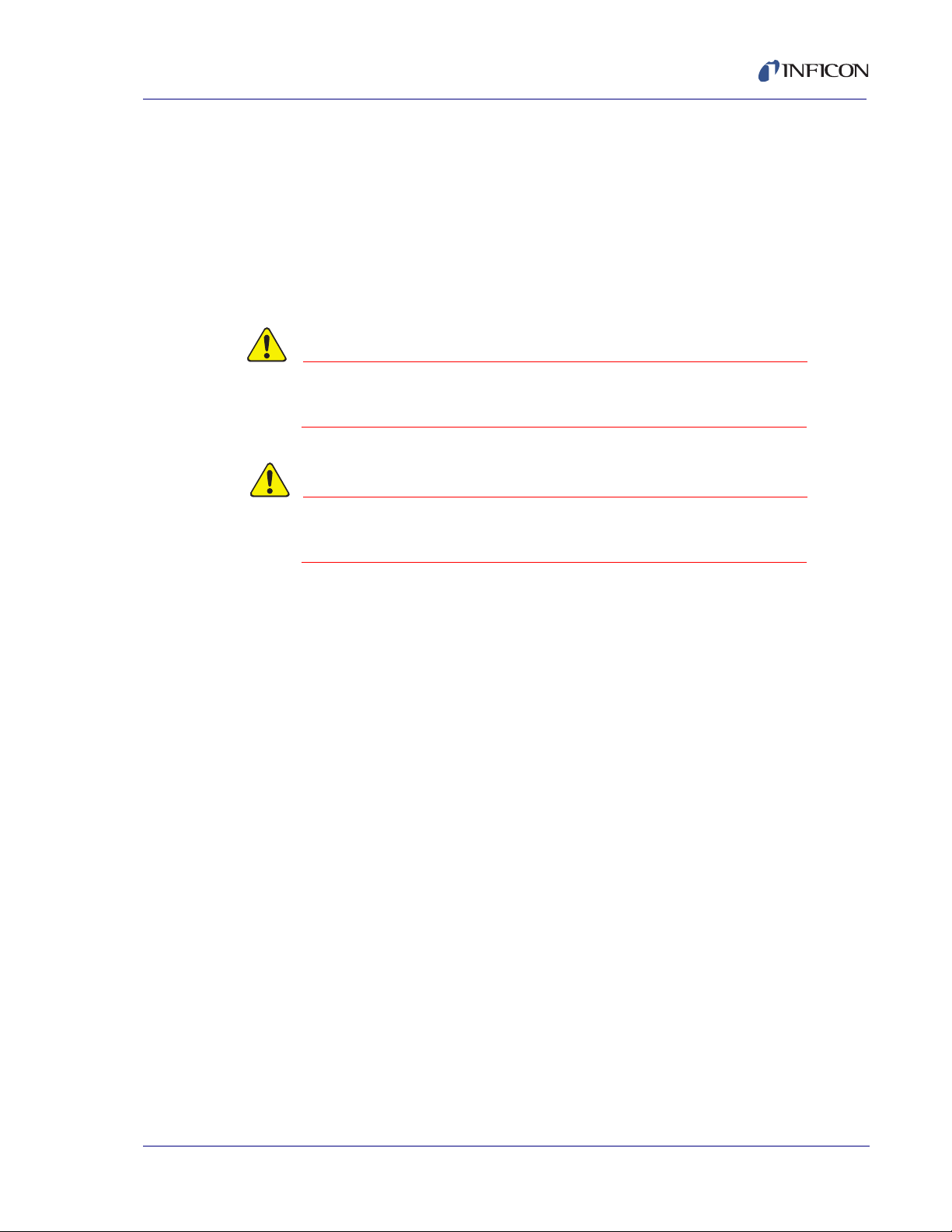
Failure to heed these messages could result in damage
to the instrument.
Failure to heed these messages could result in personal
injury.
IPN 153800-G
1 - 3
Page 12

RSH-600 Operating Manual
1.5 How To Contact INFICON
Worldwide customer support information is available under Support at
www.inficon.com where you can contact:
a Technical Support Engineer with questions regarding applications.
a Service Engineer with questions regarding troubleshooting, diagnosing or
repairing a defective sensor.
Sales and Customer Service, to find the INFICON Sales office nearest to you.
Repair Service, to find the INFICON Service Center nearest to you.
If you are experiencing a problem with your sensor, please have the following
information readily available:
the serial number of your sensor,
a description of your problem,
an explanation of any corrective action that you may have already attempted,
and the exact wording of any error messages that you may have received.
1.5.1 Returning Your Instrument
Do not return any component of your sensor to INFICON without first speaking with
a Customer Support Representative. You must obtain a Return Material
Authorization (RMA) number from the Customer Support Representative.
If you deliver a package to INFICON without an RMA number, your package will be
held and you will be contacted. This will result in delays in servicing your
instrument.
Prior to being given an RMA number, you may be required to complete a
Declaration Of Contamination (DOC) form if your sensor has been exposed to
process materials. DOC forms must be approved by INFICON before an RMA
number is issued. INFICON may require that the sensor be sent to a designated
decontamination facility, not to the factory.
IPN 153800-G
1 - 4
Page 13

1.6 Specifications
Number of Crystals. . . . . . . . . . . . . . 6
Crystal Size . . . . . . . . . . . . . . . . . . . 0.550 in. diameter
Installation Aperture . . . . . . . . . . . . . 2.0 in. diameter
Overall Length
RSH-600 w/flat head . . . . . . . . . 8.19 in. (208 mm) plus in-vac length
RSH-600 w/angled head . . . . . . 8.62 in. (219 mm) plus in-vac length
Adjustable in Vacuum Length . . . 7.9 in. (200 mm) (standard)
Power Requirement . . . . . . . . . . . . . 115 V (ac) @ 50 mA or 24 V (dc) @ 20 mA
Crystal Switching Method. . . . . . . . . Air Actuated @ 55 psi (4 kg/cm
Cooling Method . . . . . . . . . . . . . . . . Water-cooled @ 5 L/m at 2 kg/cm
RSH-600 Operating Manual
13.8 in. (350 mm)
17.7 in. (450 mm)
21.3 in. (540 mm)
25.6 in (650 mm)
2
) regulated
2
(28 psi)
Air and Water Connections. . . . . . . . (3) 1/4 in. quick connects
Operating Temperature . . . . . . . . . . 300°C max with water cooling and Standard
Head Cover
400°C max with water cooling and Copper
Head Cover
Weight . . . . . . . . . . . . . . . . . . . . . . . RSH-600 - Flat - 8.5 lb. (3.8 kg)
RSH-600 - Angled - 9.9 lb. (4.5 kg)
IPN 153800-G
1 - 5
Page 14

RSH-600 Operating Manual
1.7 Unpacking and Inspection
1 If the RSH-600 rotary sensor has not been removed from its shipping container,
do so now.
2 Carefully examine your RSH-600 sensor for damage that may have occurred
during shipping. This is especially important if you notice obvious rough
handling on the outside of the container. Immediately report any damage to the
carrier and to INFICON.
3 Do not discard the packing materials until you have taken inventory and have
at least performed a functional verification (see section 1.8.)
4 Take an inventory of your order by referring to your order invoice and verifying
that the items listed in section 1.7.1 were received.
1.7.1 Base Configuration
RSH-600 Rotary Sensor Head. . . . . . . . . . . . . . . . . . . . . . . . . . . . . . . 15320X-XX
Consult Figure 1-3 below for possible configurations.
Figure 1-3 RSH-600 Configurations
1 - 6
Crystals (2 boxes, 10 total). . . . . . . . . . . . . . . . . . . . . . . . . . . . . . . . . . . . 103200-2
IPN 153800-G
Technical Manual . . . . . . . . . . . . . . . . . . . . . . . . . . . . 153800 on 074-5000-G1 CD
Page 15

1.8 Functional Verification
Control
Voltage
115 V (ac)
or
24 V (dc)
J1 RSH
Switch
The RSH-600 is equipped to operate on a 115 V (ac), 60 Hz line or a 24 V (dc)
supply depending on the model number. You can verify the required voltage on the
body of the pneumatic valve mounted on the side of the RSH-600. The RSH-600
may be bench checked using the following procedure:
1 Connect air pressure (55 psi) via 1/4 in. plastic tubing to the air inlet fitting at
the base of the solenoid valve marked P.
2 Connect the RSH-600 as shown in Figure 1-4 or any convenient method of
applying and removing the control voltage. The RSH-600 will advance when
the voltage is applied and latch into position when it is removed. The electrical
pulse duration should be at least one second.
Figure 1-4 Electrical Connection
RSH-600 Operating Manual
IPN 153800-G
1 - 7
Page 16

RSH-600 Operating Manual
This page is intentionally blank.
1 - 8
IPN 153800-G
Page 17

RSH-600 Operating Manual
CAUTION
Chapter 2
Installation
During installation, special care must be taken to protect
the barrel surface from being damaged. Scratches or
gouges may prevent the RSH-600 from forming a good
vacuum seal to the O-ring.
Successful operation of any crystal sensor depends on proper placement,
compatibility of its construction with its operating environment and connection to
proper utilities.
NOTE: The RSH-600 should be clean and grease free when installed in the
vacuum chamber. The sensor should be handled while wearing clean
nylon gloves. If parts do become contaminated, clean them thoroughly
using a suitable solvent to avoid outgassing and excessive peeling of
deposition material from the sensor’s surfaces.
2.1 Crystal Sensor Installation
Generally, install the sensor as far as possible from the evaporation source (a
minimum of 12 in. or 30.5 cm) while still being in a position to accumulate thickness
at a rate proportional to accumulation on the substrate. Figure 2-1 shows proper
and improper methods of installing sensors.
Figure 2-1 Sensor Installation Guidelines
IPN 153800-G
2 - 1
Page 18

RSH-600 Operating Manual
J2
J1
6 in. Coaxial Cable
Oscillator
10 ft. Coaxial Oscillator
Water In
Optional Flange
Water Out
Air Solenoid Valve
Cable to QCM
To guard against spattering, use a source shutter to shield the sensor during the
initial soak periods. If the crystal is hit with even a minute particle of molten
material, it may be damaged and stop oscillating. Even in cases when it does not
completely stop oscillating, it may immediately become unstable, or shortly after
deposition begins instability may occur.
Plan the installation to insure that there are no obstructions blocking a direct path
between the sensor and the source. Install sensors in such a manner that the
center axis of the crystal is aimed directly at the source to be monitored. Verify that
the angle of the sensor location (with reference to the source) is well within the
evaporant stream.
2.2 Mounting
NOTE: The head cover must be removed from the RSH-600 prior to installation.
To remove the standard stainless steel head cover: Loosen the retainer
ring nut. Push the head cover inward while turning it counterclockwise until
it stops (1/16 of a turn). Pull the head cover outward.
To remove the optional copper head cover: Loosen the Allen head screws
that clamp the head to the RSH-600 then gently pull the head off of the
RSH-600 barrel.
The vacuum system has to be equipped with a 2.0 in. diameter aperture port. This
port must have an O-ring to provide vacuum seal to the fixed flange on the
RSH-600. If the head cover has been removed, simply slide the RSH-600 through
the 2.0 in. port. Secure the RSH-600 to the port using four 1/4-24 bolts minimum.
Reinstall the head cover. See Figure 2-2.
Figure 2-2 Typical Mounting Configuration
IPN 153800-G
2 - 2
Page 19

2.3 Adjustable Flange Installation
1 Apply a small amount of vacuum compatible grease to the entire surface of the
O-ring that is included with the Adjustable Flange and then install the O-ring
into the O-ring groove in the Adjustable Flange.
2 Loosen the Hex Socket Head screw on the Adjustable Flange.
3 Remove the cover from the RSH-600 sensor.
4 If the Crystal Holder contains any crystals, remove the holder and remove the
crystals. Reinstall the Crystal Holder.
5 Cut a piece of Kapton® tape (or equivalent), 1.5 in. (3.8 cm) to 2 in. (5 cm) wide,
to a length of approximately 6.3 in. (16 cm).
6 Position the Kapton tape with the bottom edge of the tape on the beveled
surface just below the knurled ring. Not starting at any of the three bayonet
pins, wrap the tape around the circumference of the sensor. Fold the excess
tape over the top of the Crystal Holder. See Figure 2-3.
Figure 2-3 Wrap Kapton Tape
RSH-600 Operating Manual
IPN 153800-G
7 Stand the RSH-600 sensor upright on a firm surface. Place the Adjustable
Flange, with smooth side up, over the top of the sensor barrel. With the flange
seating surface perpendicular to the sensor barrel, forcefully push the flange
downward, sliding the flange onto the sensor barrel. See Figure 2-4.
2 - 3
Page 20

RSH-600 Operating Manual
Figure 2-4 Slide Flange Onto Sensor Barrel
8 Slide the Adjustable Flange to the desired position on the sensor barrel and
then secure the flange to the barrel by tightening the Hex Socket Head screw
on the flange.
9 Remove the Kapton tape. Use a lint-free cloth dampened with Reagent grade
Isopropyl Alcohol to clean the surfaces that were in contact with the tape.
2.4 Copper Head Installation
The optional copper head must be installed after the RSH-600 has been mounted
on the vacuum system. The copper head has two main pieces, the clamping ring
and the head cover.
1 Loosen the Allen head screw on the clamping ring and on the clamp portion of
the head cover.
2 Attach the clamping ring to the head cover.
3 Remove the crystal retainer to expose two gold springs. One spring makes
contact with the backside of the retainer. The other spring makes contact with
one of the individual crystal contacts.
4 You have to align the hole in the head cover so that the crystal, that this spring
contacts, is exposed. Note the position of this spring and replace the crystal
retainer.
5 Carefully slide the cover over the barrel of the RSH-600 until it touches the
crystal retainer, then rotate the cover so that the crystal, in contact with the
spring, is centered in the hole in the cover.
IPN 153800-G
2 - 4
6 Tighten the Allen screws on the clamping ring.
Page 21

The clamping ring should be left attached to the head during crystal changing. Only
the head cover should be removed so the alignment process will not have to be
repeated unless the head is removed from the chamber.
If no flange was ordered and you are making your own adjustable flange, the
factory can provide essential dimensions and O-rings.
2.5 Cooling System
The direction of the water flow is not important. Use 1/4 inch plastic tubing to
connect one port to a water supply. The water flow rate should be 5 L/m (1.3 g/m)
at 2 kg/cm
2
(28 psi). Water temperature should be less than 30°C. Connect the
other port to a drain or water recycle system.
2.6 Air Supply
Use 1/4 in. plastic tubing to connect the air inlet port to an air supply. Make sure the
plastic tube is rated higher than 55 psi. The air pressure should be regulated to
4 kg/cm
2
(55 psi).
RSH-600 Operating Manual
2.7 Crystal Position Feedback Connections
The Crystal Position Connector has 7 pins. Pin numbers 1 through 6 correspond to
the six crystals and pin number 7 is the common pin. A short between pin 7 and
one of the pins 1 through 6 indicates the active crystal. For example, if pin 7 is
shorted to pin 1, then crystal 1 is the active crystal.
Use this connector to interface with your controller for automatic crystal selection.
Refer to your controller’s operating manual for programming instruction.
Figure 2-5 Crystal Position Connector
IPN 153800-G
2 - 5
Page 22

RSH-600 Operating Manual
Figure 2-6 Mating Connector (Male) - Crystal Position Connector
The RSH-600 provides a switch closure through connector J2 that can be used to
indicate which crystal is being used at a given time. Switch closure will be effected
by crystal positions.
Figure 2-7 Crystal Position Feedback Diagram
2.8 Protection from Evaporant
It is advisable to cover the head cover and barrel of the RSH-600 with aluminum
foil to protect it from evaporants.
2 - 6
IPN 153800-G
Page 23

3.1 Troubleshooting
WARNING
If the RSH-600 fails to function, or appears to have diminished performance, the
following Symptom/Cause/Remedy charts may be helpful.
There are no user serviceable components within the
RSH-600 sensor.
Refer all maintenance to qualified INFICON personnel.
A useful tool for diagnosing sensor head problems is the DMM (Digital Multi-Meter).
Disconnect the short oscillator cable from the feedthrough and measure the
resistance from the center pin to ground. If the reading is less than 10 megohms
the source of the leakage should be found and corrected.
RSH-600 Operating Manual
Chapter 3
Troubleshooting and Maintenance
3.2 Troubleshooting the RSH-600
Table 3-1 General Troubleshooting
SYMPTOM CAUSE REMEDY
1. Crystal fail signal on front
panel of unit will not
disappear.
IPN 153800-G
2. Unit will not advance when
crystal switch key is pressed.
Xtal switch error message
displayed.
a. Damaged crystal. a. Replace crystal.
b. Loss of electrical signal. b. Check for electrical
continuity at the BNC
connector.
a. Loss of pneumatic supply
or pressure is insufficient for
proper operation.
b. Operation has been
impaired as a result of
peeling of the material
accumulated on the face of
the aperture plate.
a. Establish air supply and
regulate to 55 psi.
b. Remove accumulated
material.
3 - 1
Page 24

RSH-600 Operating Manual
Table 3-1 General Troubleshooting (continued)
SYMPTOM CAUSE REMEDY
3. Crystal not centered in
aperture.
4. Large jumps of thickness
reading during deposition.
a. Improper alignment. a. The RSH-600 should
realign automatically. Be
sure the correct air pressure
(55 psi) is used. Contact
INFICON if the issue
persists.
a. Mode hopping. a. Mode hopping is a by
product of active oscillation
with a heavily damped
crystal. Temperature
stabilization is key in
diminishing this. Replace the
crystal.
b. Crystal near the end of its
b. Replace crystal.
life.
c. Scratches or foreign
particles on the crystal holder
seating surface.
d. Insufficient crystal cooling.
c. Clean, polish the crystal
seating surface of the crystal
holder.
d.Check water flow and
temperature.
5. Crystal ceases to oscillate
during deposition before it
reaches its "normal" life.
6. Crystal does not oscillate
or oscillates intermittently.
(both in vacuum and in air)
a. Crystal is being hit by small
droplets of molten material
a. Move the sensor further
away from the evaporant.
from the evaporation source.
b.Damaged crystal. b. Replace crystal.
c. Deposition material
built-up on the edge of the
d. Clean the crystal carousel
aperture plate.
crystal carousel aperture
plate and touching the
crystal, partially masking full
crystal area.
a. Defective or damaged
a. Replace crystal.
crystal.
b. Existence of electrical
short or poor electrical
contacts.
Check for electrical continuity
and short in sensor cable,
electrical connection
assembly, feedthroughs, and
crystals carousel.
d. Insufficient crystal cooling.
d.Check water flow and
temperature.
IPN 153800-G
3 - 2
Page 25

Table 3-1 General Troubleshooting (continued)
SYMPTOM CAUSE REMEDY
RSH-600 Operating Manual
7. Crystal oscillates in
vacuum but stops oscillation
after open to air.
8. Thermal instability: large
changes in thickness reading
during source warm-up
(usually causes thickness
reading to decrease) and
after the termination of
deposition (usually causes
thickness reading to
increase.)
a. Crystal was near the end
of its life; opening to air
causes film oxidation which
increases film stress.
b. Excessive moisture
accumulates on the crystal.
a. Inadequate cooling
water/cooling water
temperature too high.
b. Excessive heat input to the
crystal.
c. Crystal not seated properly
in holder.
a. Replace crystal.
b. Turn off cooling water to
sensor prior to venting, flow
warm water through sensor
while chamber is open.
a. Check cooling water flow
rate, be certain that cooling
water temperature is less
than 30°C.
b. If heat is due to radiation
from the evaporation source,
move sensor further away
from source and use
sputtering crystals for better
thermal stability.
c. Clean or polish the crystal
seating surface on the crystal
holder.
9. Poor thickness
reproducibility.
a. Variable source flux
distribution.
a. Move sensor to a more
central location to reliably
sample evaporant, ensure
constant relative pool height
of melt, avoid tunneling into
the melt.
b. Sweep, dither, or position
where the electron beam
IPN 153800-G
strikes the melt has been
changed since the last
deposition.
b. Maintain consistent source
distribution by maintaining
consistent sweep
frequencies, sweep
amplitude and electron beam
position settings.
c. Material does not adhere
to the crystal.
c. Make certain the crystal
surface is clean; avoid
touching crystal with fingers,
make use of an intermediate
adhesion layer.
3 - 3
Page 26

RSH-600 Operating Manual
3.3 Maintain the Temperature of the Crystal
Periodically, measure the water flow rate through the crystal sensor to verify that it
meets or exceeds the value specified in section 2.5 on page 2-5. Depending upon
the condition of the cooling water used, the addition of an in-line water filtering
cartridge system may be necessary to prevent flow obstructions. Many system
coaters use parallel water supply taps that provide high total flows. An obstruction
or closed valve in the pipe that supplies water to the sensor head would not result
in a noticeable reduction of total flow. The best test is to directly monitor the flow
leaving the sensor.
The crystal requires sufficient water cooling to sustain proper operational and
temperature stability. Ideally, a constant heat load is balanced by a constant flow of
water at a constant temperature. INFICON quartz crystals are designed to provide
the best possible stability under normal operating conditions. No crystal can
completely eliminate the effects of varying heat loads. Sources of heat variation
include radiated energy emanating from the evaporant source and from substrate
heaters.
3.4 Use the Optimum Crystal Type
Certain materials, especially dielectrics, may not adhere strongly to the crystal
surface and may cause erratic readings. For many dielectrics, adhesion is
improved by using crystals with alloy coated electrodes. Gold is preferred for other
applications.
3.5 Crystal Concerns when Opening the Chamber
Thick deposits of some materials, such as SiO, Si and Ni will normally peel off the
crystal when it is exposed to air, due to changes in film stress caused by gas
absorption. When peeling material is observed, replace the crystal.
3.6 Crystal Holder Maintenance
In many applications, the surface where the crystal contacts the crystal holder may
require periodic cleaning. Material buildup on this surface can cause erratic or poor
electrical contact between the crystal and the sensor body. This buildup can also
cause a reduction in thermal transfer from the crystal to the sensor body. Both of
these can result in excessive rate noise or premature or intermittent crystal failure.
Cleaning may be accomplished by gently buffing the crystal holder to crystal
seating surface with a white Scotch-Brite™ pad followed by an ultrasonic bath in
soap solution followed by thorough rinsing in deionized water and drying or by
ultrasonic cleaning and rinsing only.
IPN 153800-G
3 - 4
Page 27

NOTE: The crystal holder seating surface is machined to a very fine finish
CAUTION
(16 micro inches rms). This high quality finish is essential to provide good
electrical and thermal contact with the crystal. Applying excessive force
during cleaning or using overly abrasive cleaning materials may damage
this finish and reduce sensor performance.
3.7 Crystal Replacement
Always use clean nylon lab gloves and clean plastic tweezers when handling the
crystal. Handle the crystals only by their edges. Anything that comes in contact with
the crystal surfaces may leave contamination, which may lead to poor film
adhesion. Poor film adhesion will result in high rate noise and premature crystal
failure.
Do not use metal tweezers to handle crystals. Metal
tweezers may chip the edge of the crystal.
RSH-600 Operating Manual
1 Remove aluminum foil (if installed).
2 Remove the stainless steel head cover.
2a Loosen the retainer ring nut.
2b Push the head cover inward while turning it counterclockwise until it stops
(1/16 of a turn.)
2c Pull the head cover outward and remove head cover from the head barrel.
3 Remove the copper head cover.
3a Loosen the three Allen head screws that attach the head cover to the copper
clamping ring. (Leave clamping ring attached.)
3b Carefully slide the head off of the barrel of the RSH.
4 Loosen center screw of the head to release crystal retainer.
IPN 153800-G
5 Remove the remaining three screws (on the backside of the retainer) to
separate the head from the spring retainer.
6 Remove the used crystals and replace new ones into the crystal holder. Make
sure to place the crystal so that the solid electrode is facing out of the head.
7 Put the spring retainer and crystal housing back together and tighten the three
screws being careful not to deform the crystal springs or break the crystals.
8 Place the complete crystal retainer assembly back on the head barrel, observe
and line it up with the indexed pin. Tighten the screw.
9 Replace the head cover.
NOTE: Crystal replacement time can be reduced by using a spare crystal holder.
3 - 5
Page 28

RSH-600 Operating Manual
This page is intentionally blank.
3 - 6
IPN 153800-G
Page 29

Accessories and Replacement Parts
4.1 Accessories and Replacement Parts
Flat Copper Head Cover . . . . . . . . . . . . . . . . . . . . . . . . . . . . . . . . . . . . . . 153731
Angled Copper Head Cover . . . . . . . . . . . . . . . . . . . . . . . . . . . . . . . . . . .153731-2
Flat Stainless Steel Head Cover (See Figure 4-1) . . . . . . . . . . . . . . . . . . . 153708
Angled Stainless Steel Head Cover (See Figure 4-2) . . . . . . . . . . . . . . . . 153713
Flat Crystal Retainer Assembly (See Figure 4-1). . . . . . . . . . . . . . . . . . . . 153204
Angled Crystal Retainer Assembly (See Figure 4-2) . . . . . . . . . . . . . . . . 153204-2
Flat Crystal Holder (See Figure 4-1). . . . . . . . . . . . . . . . . . . . . . . . . . . . . . 153710
Angled Crystal Holder (See Figure 4-2) . . . . . . . . . . . . . . . . . . . . . . . . . . . 153716
RSH-600 Operating Manual
Chapter 4
Flat Spring Retainer Assembly (See Figure 4-1) . . . . . . . . . . . . . . . . . . . . 153706
Angled Spring Retainer Assembly (See Figure 4-2) . . . . . . . . . . . . . . . . . 153714
Flat Spring Retainer Contact Kit (See Figure 4-1) . . . . . . . . . . . . . . . . . . . 153724
Spring Contact (See Figure 4-1 and Figure 4-2) . . . . . . . . . . . . . . . . . . . . 153726
Flat Retainer Screw (See Figure 4-1). . . . . . . . . . . . . . . . . . . . . . . . . . . . . 153709
Angled Retainer Screw (See Figure 4-2) . . . . . . . . . . . . . . . . . . . . . . . . . . 153715
Angled Retainer Spacer (See Figure 4-2) . . . . . . . . . . . . . . . . . . . . . . . . . 153717
M3x6 Screw for Flat Crystal Retainer Assembly (See Figure 4-1). . . . . . . 144-101
M3x12 Screw for Angled Crystal Retainer Assembly (See Figure 4-2) . . . 144-224
IPN 153800-G
Solenoid Valve Assembly, 24 V (See Figure 5-1). . . . . . . . . . . . . . . . . . . . 153707
Crystal Position Male Connector (See Figure 5-1). . . . . . . . . . . . . . . . . . . 889128
Adjustable Flange (See Figure 5-1 and Figure 5-2) . . . . . . . . . . . . . . . . . . 153202
O-ring for Adjustable Flange (see Figure 5-1) . . . . . . . . . . . . . . . . . . . . . . 803188
4 - 1
Page 30

RSH-600 Operating Manual
Stainless Steel Cover
Crystal Holder
P/N 153708
P/N 153710
Spring Contact
Retainer Screw
Spring Retainer
Spring Retainer
P/N 153726
P/N 153709
Copper Cover (not shown)
P/N 153731
M3x6 Screw
P/N 144-101
Contact Kit (set of 6)
P/N 153724
Assembly
P/N 153706
Crystal Retainer
Assembly
P/N 153204
Figure 4-1 Rotary Sensor Head - Flat
IPN 153800-G
4 - 2
Page 31

Figure 4-2 Rotary Sensor Head - Angled
Stainless Steel Cover
Copper Cover (not shown)
Crystal Holder
P/N 153716
P/N 153713
P/N 153731-2
Spring Retainer
Assembly
P/N 153714
Crystal Retainer
Assembly
P/N 153204-2
Retainer Screw
P/N 153715
M3x12 Screw
P/N 144-224
Spring Contact
P/N 153726
Retainer Spacer
P/N 153717
RSH-600 Operating Manual
IPN 153800-G
4 - 3
Page 32

RSH-600 Operating Manual
This page is intentionally blank.
4 - 4
IPN 153800-G
Page 33

Figure 5-1 Sensor Head
φ50
208
(43)
Flat Head ±2
(21)
Ø50
Ø74
(43.5)
(Ø58)
15
Solenoid Valve
Air Inlet
Tube O.D. Ø1/4 in
Flat Head
350 mm (13.8 in)
540 mm (21.3 in)
650 mm (25.6 in)
450 mm (17.7 in)
200 mm (7.9 in)
Crystal Aperture
Connector
Crystal Position
BNC Connector
Sensor Crystal
O-Ring
Optional
Mounting Flange
Mounting Surface
7.1
Ø50
φ50
19.1
Crystal Aperture
FLAT HEAD
ANGLE HEAD
Angle Head ±2
Angle Head
361 mm (14.2 in)
551 mm (21.7 in)
661 mm (26.0 in)
461 mm (18.2 in)
211 mm (8.3 in)
Water Inlet
Crystal Aperture
BCD Ø74 4-Ø5.5
15
Mounting Holes
74
74
(118.1)
Ø84
(Tube Ø1/4")
DIMENSIONS IN mm EXCEPT WHEN NOTED
Water Outlet
(Tube 1/4 in. diameter)
RSH-600 Operating Manual
Chapter 5
Outline Drawings
IPN 153800-G
5 - 1
Page 34

RSH-600 Operating Manual
5 - 2
Figure 5-2 Adjustable Flange (dimensions in inches)
IPN 153800-G
 Loading...