


 Loading...
FULL MANUAL
HF/50 MHz TRANSCEIVER
i7300
INTRODUCTION
1PANEL DESCRIPTION
2INSTALLATION AND CONNECTIONS
3BASIC OPERATION
4RECEIVING AND TRANSMITTING
5SCOPE OPERATION
6VOICE RECORDER FUNCTIONS
7VOICE TX MEMORY OPERATION
8USING AN SD CARD
9MEMORY OPERATION
10SCANS
11ANTENNA TUNER OPERATION
12SET MODE
13OTHER FUNCTIONS
14MAINTENANCE
15UPDATING THE FIRMWARE
16SPECIFICATIONS
17OPTIONS
18CONNECTOR INFORMATION
19CONTROL COMMAND
INDEX
ABOUT CE

Previous view
Thank you for choosing this Icom product. The IC-7300 HF/50 MHz TRANSCEIVER is designed and built with Icom’s state of the art technology and craftsmanship. With proper care, this product should provide you with years of trouble-free operation. We appreciate you making the IC-7300 your transceiver of choice, and hope you agree with Icom’s philosophy of “technology first.” Many hours of research and development went into the design of your IC-7300.
IMPORTANT
READ ALL INSTRUCTIONS carefully completely before using the transceiver.
SAVE THIS INSTRUCTION MANUAL— This instruction manual contains full operating instructions for the IC-7300.
FEATURES
••RF Direct Sampling System
The IC-7300 employs an RF direct sampling system. RF signals are directly converted to digital data and processed in the FPGA. This system is a leading technology marking an epoch in amateur radio.
••Real-Time Spectrum Scope
The spectrum scope is class-leading in resolution, sweep speed and dynamic range. When you touch the scope screen on the intended signal, the touched area is magnified. The large 4.3 inch color TFT touch LCD offers intuitive operation.
••New “IP+” Function
The new IP Plus function improves 3rd order intercept point (IP3) performance. When a weak signal is received adjacent to strong interference, the AD converter is optimized against signal distortion.
••Class Leading RMDR and Phase Noise
Characteristics
The RMDR is improved to about 97dB (typical value) and Phase Noise characteristics are also improved about 15dB (at 1 kHz frequency separation) compared to the IC-7200.
••A 4.3 inch touch screen color display
••A built-in automatic antenna tuner
••Multi-function control for easy settings
EXPLICIT DEFINITIONS
WORD |
DEFINITION |
|
R DANGER! |
Personal death, serious injury or an |
|
explosion may occur. |
||
|
||
R WARNING! |
Personal injury, fire hazard or electric |
|
shock may occur. |
||
|
||
CAUTION |
Equipment damage may occur. |
|
|
Recommended for optimum use. No |
|
NOTE |
risk of personal injury, fire or electric |
|
|
shock. |
SUPPLIED ACCESSORIES
|
Spare fuse |
Spare fuse |
|
(5 A) |
(25 A) |
Hand microphone |
|
|
(HM-219) |
|
|
|
DC power cable |
|
ACC plug |
(3 m: 9.8 ft) |
|
(13 pin) |
|
|
CW key plug |
|
Spare fuse |
(6.35 mm: 1/4" Stereo) |
|
(30 A) |
Speaker plug |
|
|
(3.5 mm: 1/8" Stereo) |
|
|
|
|
DC power cable |
CD |
For European versions |
|
LDifferent types of accessories may be supplied, or may not be supplied depending on the transceiver version.
This product includes RTOS “RTX” software, and is licensed according to the software license.
This product includes “zlib” open source software, and is licensed according to the open source software license.
This product includes “libpng” open source software, and is licensed according to the open source software license.
Refer to the Text files in the License folder of included CD for information on the open source software being used by this product.
i

Previous view
FCC INFORMATION
This equipment has been tested and found to comply with the limits for a Class B digital device, pursuant to part 15 of the FCC Rules. These limits are designed to provide reasonable protection against harmful interference in a residential installation. This equipment generates, uses and can radiate radio frequency energy and, if not
installed and used in accordance with the instructions, may cause harmful interference to radio communications. However, there is no guarantee that interference will not occur in a particular installation. If this equipment does cause harmful interference to radio or television reception, which can be determined by turning the equipment off and on, the user is encouraged to try to correct the interference by one or more of the following measures:
••Reorient or relocate the receiving antenna.
••Increase the separation between the equipment and receiver.
••Connect the equipment into an outlet on a circuit different from that to which the receiver is connected. ••Consult the dealer or an experienced radio/TV technician for help.
WARNING: MODIFICATION OF THIS DEVICE TO RECEIVE CELLULAR RADIOTELEPHONE SERVICE SIGNALS IS PROHIBITED UNDER FCC RULES AND FEDERAL LAW.
CAUTION: Changes or modifications to this device, not expressly approved by Icom Inc., could void your authority to operate this device under FCC regulations.
DISPOSAL
The crossed-out wheeled-bin symbol on your product, literature, or packaging reminds you that in the European Union, all electrical and electronic products, batteries, and accumulators (rechargeable batteries) must be taken to designated collection locations at the end of their working life. Do not dispose of these products as unsorted municipal waste.
Dispose of them according to the laws in your area.
ABOUT CE AND DOC
Hereby, Icom Inc. declares that the versions of IC-7300 which have the “CE” symbol on the product, comply with the essential requirements of the Radio Equipment Directive, 2014/53/EU, and the restriction of the use of certain hazardous substances in electrical and electronic equipment Directive, 2011/65/EU.
The full text of the EU declaration of conformity is available at the following internet address: http://www.icom.co.jp/world/support
TRADEMARKS
Icom, Icom Inc. and the Icom logo are registered trademarks of Icom Incorporated (Japan) in Japan, the United States, the United Kingdom, Germany, France, Spain, Russia, Australia, New Zealand and/or other countries.
Microsoft and Windows are registered trademarks of Microsoft Corporation in the United States and/or other countries. Adobe, Acrobat, and Reader are either registered trademarks or trademarks of Adobe Systems Incorporated in the United States and/or other countries.
All other products or brands are registered trademarks or trademarks of their respective holders.
Icom is not responsible for the destruction, damage to, or performance of any Icom or non-Icom equipment, if the malfunction is because of:
••Force majeure, including, but not limited to, fires, earthquakes, storms, floods, lightning, or other natural disasters, disturbances, riots, war, or radioactive contamination.
••The use of Icom transceivers with any equipment that is not manufactured or approved by Icom.
ii

Previous view
ABOUT THE TOUCH SCREEN
DD Touch operation
In the Full manual or Basic manual, the touch operation is described as shown below.
Touch
If the display is touched briefly, one short beep sounds.
Touch for 1 second
If the display is touched for 1 second, one short and one long beep sound.
DD Touch screen precautions
••The touch screen may not properly work when the
LCD protection film or sheet is attached. ••Touching the screen with your finger nails, sharp topped object and so on, or touching the screen
hard may damage it.
••Tablet PC’s operations such as flick, pinch in and pinch out cannot be performed on this touch screen.
DD Touch screen maintenance
••If the touch screen becomes dusty or dirty, wipe it clean with a soft, dry cloth.
••When you wipe the touch screen, be careful not to push it too hard or scratch it with your finger nails.
Otherwise you may damage the screen.
ABOUT THE SUPPLIED CD
The following items are included on the CD.
••Full manual (English)
Instructions for full operations in English, the same as this manual.
••Basic manual (English)
Instructions for basic operations in English.
••Full manual (German)
Instructions for full operations in German.
••Basic manual (Multi-language)
Instructions for basic operations in multiple languages.
••Schematic diagram
Includes the schematic and block diagrams.
••HAM radio Terms (English)
A glossary of HAM radio terms in English.
••Adobe® Acrobat® Reader® Installer
Installer for Adobe® Acrobat® Reader®.
To read the manuals or Schematic diagram, Adobe® Acrobat® Reader® is required. If you have not installed it, please install the Adobe® Acrobat® Reader® on the CD or download it from Adobe Systems Incorporated’s website.
A PC with the following Operating System is required. ••Microsoft® Windows® 10
••Microsoft® Windows® 8.1 ••Microsoft® Windows® 7
Starting the CD
1.Insert the CD into the CD drive.
2.Double click “Menu.exe” on the CD.
••Depending on the PC setting, the menu screen shown below is automatically displayed.
3.Click the desired button to open the file.
LTo close the Menu screen, click [Quit].
Opens the English |
Opens the English Full |
Basic manual |
manual (this manual) |
|
Opens the |
|
Schematic |
|
diagram |
Opens |
|
the multi- |
Opens the |
language |
German Full |
Basic manual |
manual |
Opens the
Glossary
Installs the Adobe® |
Closes the Menu screen |
Acrobat® Reader® |
|
LDifferent types of menu screen may be displayed, depending on the transceiver version.
iii

Previous view
Functions and features of Adobe® Acrobat® Reader®
The following functions and features can be used with Adobe® Acrobat® Reader®.
•Keyword search
Click “Find (Ctrl+F)” or “Advanced Search
(Shift+Ctrl+F)” in the Edit menu to open the search screen. This is convenient when
searching for a particular word or phrase in this manual.
*The menu screen may differ, depending on the Adobe® Acrobat® Reader® version.
Click to open the find or search screen or advanced search screen.
• Printing out the desired pages.
Click “Print” in File menu, and then select the paper size and page numbers you want to print.
*The printing setup may differ, depending on the printer. Refer to your printer’s instruction manual for details.
*Select “A4” size to print out the page in the equalized size.
•Find screen
•Advanced search screen
• Read Out Loud feature.
The Read Out Loud feature reads aloud the text in this Instruction Manual.
Refer to the Adobe® Acrobat® Reader® Help for the details.
(This feature may not be usable, depending on your PC environment including the operating system.)
*The screen may differ, depending on the Adobe® Acrobat® Reader® version.
iv
Previous view
ABOUT THE INSTRUCTIONS
The Full and Basic manuals are described based on the following:
“ ” (Quotation marks):
Used to indicate icons, setting items, and screen titles displayed on the screen.
The screen titles are also indicated in uppercase letters. (Example: FUNCTION screen)
Detailed instruction
1. Push MENU .
[ ] (brackets):
Used to indicate keys.
Routes to the set modes and setting screens
Routes to the set mode, setting screen and the setting items are shown in the following manner.
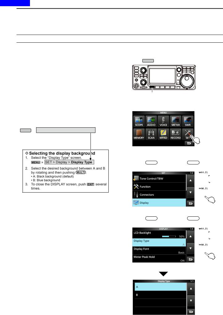
MENU » SET > Display > Display Type
Instruction example
Push
••Opens the MENU screen.
2. Touch [SET].
MENU screen ••Opens the SET screen.
3.Rotate MULTI , and then push MULTI to select
“Display.”
 Rotate
 Push
Push
SET screen
4.Rotate MULTI , and then push MULTI to select
“Display Type.”
 Rotate
 Push
Push
DISPLAY screen
“Display Type” screen
v

Previous view
PRECAUTIONS
R DANGER HIGH RF VOLTAGE! NEVER touch an antenna or antenna connector while transmitting. This could cause an electrical shock or burn.
R DANGER! NEVER operate the transceiver near unshielded electrical blasting caps or in an explosive atmosphere. This could cause an explosion and death.
R WARNING RF EXPOSURE! This device emits Radio Frequency (RF) energy. Extreme caution should be observed when operating this device. If you have any questions regarding RF exposure and safety standards please refer to the Federal Communications Commission
Office of Engineering and Technology’s report on
Evaluating Compliance with FCC Guidelines for Human Radio Frequency Electromagnetic Fields (OET Bulletin 65).
R WARNING! NEVER operate the transceiver with a headset or other audio accessories at high volume levels. If you experience a ringing in your ears,reduce the volume or discontinue use.
R WARNING! NEVER apply AC power to the [DC13.8V] socket on the transceiver rear panel. This could cause a fire or damage the transceiver.
R WARNING! NEVER apply more than 16 V DC to the [DC13.8V] socket on the transceiver rear panel. This could cause a fire or damage the transceiver.
R WARNING! NEVER reverse the DC power cable polarity. This could cause a fire or damage the transceiver.
R WARNING! NEVER remove the fuse holder on the DC power cable. Excessive current caused by a short could cause a fire or damage the transceiver.
R WARNING! NEVER let metal, wire or other objects contact the inside of the transceiver, or make incorrect contact with connectors on the rear panel. This could cause an electric shock or damage the transceiver.
R WARNING! NEVER operate or touch the transceiver with wet hands. This could cause an electric shock or damage to the transceiver.
R WARNING! Immediately turn OFF the transceiver power and remove the DC power cable from the transceiver if it emits an abnormal odor, sound or smoke. Contact your Icom dealer or distributor for advice.
R WARNING! NEVER put the transceiver on an unstable place where the transceiver may suddenly move or fall. This could cause an injury or damage the transceiver.
R WARNING! NEVER operate the transceiver during a lightning storm. It may result in an electric shock, cause a fire or damage the transceiver. Always disconnect the power source and antenna before a storm.
CAUTION: NEVER expose the transceiver to rain, snow or any liquids.
CAUTION: NEVER change the internal settings of the transceiver. This could reduce transceiver performance and/or damage to the transceiver. The transceiver warranty does not cover any problems caused by unauthorized internal adjustments.
CAUTION: NEVER install or place the transceiver in a place without adequate ventilation, or block any cooling vents on the top, rear, sides or bottom of the transceiver. Heat dissipation may be reduced and damage the transceiver.
CAUTION: NEVER use harsh solvents such as Benzine or alcohol when cleaning, as they will damage the transceiver surfaces.
CAUTION: NEVER leave the transceiver in areas with temperatures below –10°C (+14°F) or above +60°C (+140°F) for mobile operations.
CAUTION: NEVER place the transceiver in excessively dusty environments. This could damage the transceiver.
DO NOT place the transceiver against walls or putting anything on top of the transceiver. This may overheat the transceiver.
BE CAREFUL! The Main unit will become hot when operating the transceiver continuously for long periods of time.
CAUTION: If you use a linear amplifier, set the transceiver’s RF output power to less than the linear amplifier’s maximum input level, otherwise a high input could damage the linear amplifier.
CAUTION: Use only Icom supplied or optional microphones. Other manufacturer’s microphones may have different pin assignments, and could damage the connector and/or the transceiver.
NEVER leave the transceiver in an insecure place to avoid use by unauthorized persons.
Turn OFF the transceiver’s power and/or disconnect the AC power cable when you will not use the transceiver for a long period of time.
Turn OFF the transceiver’s power and/or disconnect the DC power cable when you will not use the transceiver for long period of time.
The LCD display may have cosmetic imperfections that appear as small dark or light spots. This is not a
malfunction or defect, but a normal characteristic of LCD displays.
vi
Previous view |
|
|
|
Section 1 |
PANEL DESCRIPTION |
|
|
|
|
Front panel.............................................................................. |
1-2 |
|
|
Rear panel............................................................................... |
1-4 |
|
|
Touch screen........................................................................... |
1-5 |
|
|
DDMulti-function menus....................................................... |
1-7 |
|
|
DDMENU screen.................................................................. |
1-7 |
|
|
DDFUNCTION screen.......................................................... |
1-7 |
|
|
DDQUICK MENU.................................................................. |
1-7 |
|
|
Keyboard entering and editing................................................ |
1-8 |
|
|
DDEntering and editing characters....................................... |
1-8 |
|
|
DDKeyboard types............................................................... |
1-8 |
|
|
DDEntering and editing........................................................ |
1-8 |
|
|
DDEntering and editing example.......................................... |
1-9 |
1-1

Previous view
1 PANEL DESCRIPTION
Front panel
This section describes the keys, controls and dials that you use to operate the IC-7300. Refer to the pages posted beside each key, control, or dial for details.
q |
|
|
w |
|
|
e |
!9 |
|
r |
||
|
||
t |
|
y
u i |
o !0 !1 !2 !3 !4!5!6 |
!7 !8 |
q POWER KEY POWER (p. 3-2)
Turns the transceiver ON or OFF.
w TRANSMIT KEY TRANSMIT (p. 3-10)
Toggles between transmit and receive.
e ANTENNA TUNER KEY TUNER (p. 11-2)
Turns the antenna tuner ON or OFF, or activates the tuner.
r VOX/BREAK-IN KEY VOX/BK-IN
Turns the VOX function (p. 4-10) and Break-in function (p. 4-15) ON or OFF.
t HEADPHONE JACK [PHONES] (p. 2-2)
Connects to a standard stereo headphones.
y MICROPHONE CONNECTOR [MIC] (p. 2-2)
Connects to the supplied or an optional microphone.
u VOLUME CONTROL AF
 RF/SQL (p. 3-2)
Adjusts the audio output level.
i SD CARD SLOT [SD CARD] (p. 8-2)
Accepts an SD card.
o RF GAIN CONTROL/SQUELCH CONTROL
AF
 RF/SQL (p. 3-10)
Adjusts the RF gain and squelch threshold levels.
!0 MENU KEYMENU (p. 1-7)
Opens the MENU screen.
!1 FUNCTION KEYFUNCTION (p. 1-7)
Displays the FUNCTION screen.
!2 MINI SCOPE KEYM.SCOPE (p. 5-2)
Displays the Mini Scope or Spectrum Scope.
!3 QUICK KEYQUICK (p. 1-7)
Displays the QUICK MENU.
!4 EXIT KEYEXIT (p. 1-7)
Exits a setting screen or returns to the previous screen.
!5 AUTO TUNE KEYAUTO (p. 4-16)
TUNE
Automatically tunes the operating frequency to a received CW signal.
!6 SPEECH/LOCK KEYSPEECH
Announces the operating frequency or receiving mode (p. 13-2), or electronically locks MAIN DIAL (p.3-10).
!7 FRICTION ADJUSTER (13-2)
Adjusts the friction of MAIN DIAL .
!8 MAIN DIALMAIN DIAL (p. 3-4)
Changes the operating frequency.
!9MEMORY CHANNEL UP/DOWN KEY ▲ / ▼
(p. 9-3)
Changes the Memory channel.
1-2

Previous view
1 PANEL DESCRIPTION
Front panel (Continued)
#4#3#2 #1 |
#0 |
@9@8@7@6@5@4@3 |
|
|
@2 |
|
|
@1 |
|
|
@0 |
@0 MEMO PAD KEYMPAD (p. 9-6)
Sequentially calls up the contents in the Memo Pads, or saves the displayed contents into the Memo Pad.
@1 VFO/MEMORY KEYV/M (p. 3-2)
Switches between the VFO and Memory mode, or copies the memory channel contents to the VFO.
@2 CLEAR KEYCLEAR
Clears the RIT (p. 4-3) or  TX shift frequency (p. 4-11).
@3 A/B KEYA/B (p. 3-2)
Switches between VFO A and VFO B, or sets the selected VFO’s frequency to the other VFO.
@4TX KEY |
TX (p. 4-11) |
|||
Turns the |
TX function ON or OFF. |
|||
|
RIT KEY |
|
(p. 4-3) |
|
@5 |
RIT |
|
|
|
Turns the Receiver Incremental Tuning (RIT) |
||||
function ON or OFF. |
||||
|
SPLIT KEY |
(p. 4-13) |
||
@6 |
|
SPLIT |
|
|
Turns the Split function ON or OFF.
@7 MULTI-FUNCTION CONTROLMULTI (p. 1-7)
Displays the Multi-function menu for various adjustments, or selects a desired item.
@8TRANSMIT FREQUENCY CHECK KEY XFC
(p. 4-13)
Enables you to monitor the transmit frequency while holding it down in the Split mode.
@9 TX/RX INDICATOR (p. 3-10)
Lights red while transmitting and lights green while receiving.
#0 NOISE REDUCTION KEYNR (p. 4-9)
Turns the Noise Reduction function ON or OFF.
#1 NOTCH KEYNOTCH (p. 4-9)
Turns the Notch filter ON or OFF.
#2TWIN PASSBAND TUNING CONTROL 
(p. 4-5)
Adjusts the IF filter’s passband width by rotating, and clears the setting by holding down for 1 second.
#3 PREAMP/ATTENUATOR KEYP.AMPATT (p. 4-3)
Turns ON or OFF, and selects one of two receive
RF preamplifiers or turns the Attenuator ON or OFF.
#4 NOISE BLANKER KEYNB (p. 4-8)
Turns the Noise Blanker ON or OFF.
1-3
Previous view
1 PANEL DESCRIPTION
Rear panel
!2 !1 !0o i
q |
w |
e |
qDC POWER SOCKET [DC 13.8 V] (p. 2-3)
Accepts 13.8 V DC through the DC power cable.
wGROUND TERMINAL [GND] (p. 2-2)
Connects to ground to prevent electrical shocks, TVI, BCI and other problems.
eANTENNA CONNECTOR [ANT] (p. 2-3)
Connects to a 50 Ω PL-259 coax connector.
rSOCKET [ACC] (p. 2-3)
Connects to devices to control an external unit or to control the transceiver.
tUSB PORT (B TYPE) [USB] (p. 2-3)
Connects to a PC.
yCI-V REMOTE CONTROL JACK [REMOTE]
(p. 2-3)
Connects to a PC or other transceiver for external control.
uEXTERNAL SPEAKER JACK [EXT-SP] (p. 2-3)
Accepts a 4~8 Ω external speaker.
r t y u
iKEY JACK [KEY] (p. 2-3)
Connects to a straight key, external electronic keyer, or a paddle with 6.35 mm (1⁄4") stereo plug.
oSEND CONTROL JACK [SEND] (p. 2-3)
Connects to control transmit with non-Icom external units.
!0ALC INPUT JACK [ALC] (p. 2-3)
Connects to the ALC output jack of a non-Icom linear amplifier.
!1TUNER CONTROL SOCKET [TUNER] (p. 2-3)
Accepts the control cable from an optional AH-4 automatic antenna tuner or AH-740 automatic tuning antenna.
!2COOLING FAN
Cools the PA unit when necessary.
1-4

Previous view
1 PANEL DESCRIPTION
Touch screen
This section describes the icons, screens, dialogs, readouts and so on that are displayed on the IC-7300 screen. Refer to the pages posted beside each item for details.
q |
w |
e r t y u i o !0 !1 !2 |
 !3
!3
 !4
!4
 !5
!5
q TUNE ICON  (p. 11-2)
Appears while tuning the antenna.
w MODE INDICATOR  (p. 3-3)
Displays the selected operating mode.
e PASSBAND WIDTH INDICATOR 
(p. 4-5)
Graphically displays the passband width for twin PBT operation and the center frequency for IF shift operation.
r TONE INDICATOR  (p. 4-29)
Displays the selected tone type in the tone operation mode.
t IF FILTER INDICATOR  (p. 4-6)
Displays the selected IF filter.
y QUICK TUNING ICON  (p. 3-4)
Appears when the Quick Tuning Step function is ON.
u IP PLUS ICON (p. 4-7)
Appears when the IP Plus function is ON.
i MEMORY NAME READOUT/AUTO TUNE ICON
Displays the memory name if entered (p. 9-5), or displays the “AUTOTUNE” icon when the Auto Tuning function is ON (p. 4-16).
o M1~M8/T1~T8/OVF ICON 
Displays “M1”~“M8” while “External Keypad” on the CONNECTORS screen is set to ON and using the Memory Keyer function (p. 4-18). Displays
“T1”~“T8” while using the Voice TX memory. (p. 7-4) Displays “OVF” when an excessively strong signal is received.
!0 VOICE RECORDER ICON |
(p. 6-2) |
Appears while recording. |
|
!1 SD CARD ICON (p. 8-2)
Appears when an SD card is inserted, or blinks while accessing the SD card.
!2 CLOCK READOUT |
(p. 12-11) |
Displays the current local time.
Touch the readout to display both the current local time and UTC time.
!3 SPLIT ICON |
(p. 4-13) |
|
Appears when the Split function is ON. |
||
!4 VFO/MEMORY ICON |
(p. 3-2) |
|
“VFO A” or “VFO B” appears when the VFO mode is selected, and “MEMO” appears when the Memory mode is selected.
!5 MEMORY CHANNEL READOUT (p. 3-2)
Displays the selected memory channel number.
1-5

Previous view
1 PANEL DESCRIPTION
Touch screen (Continued)
@7 @6
@6
@5
@4
@3
@2
!6 LOCK ICON |
(p. 3-10) |
Appears while the Lock Function is ON. |
|
appears while the 1/4 Tuning function is ON. |
|
(p. 3-5) |
|
!7 RIT ICON |
(p. 4-2) |
Appears while the RIT function is ON.
!8TX ICON  (p. 4-11)
Appears while the  TX function is ON.
!9 SHIFT FREQUENCY READOUT
Displays the shift offset of the RIT (p. 4-2) or
 TX (p. 4-11) functions, while the functions are ON.
@0 SPECTRUM SCOPE SCREEN (p. 5-2)
Displayed while using the Spectrum Scope.
@1 FUNCTION DISPLAY
Displays the operating parameters, modes, frequencies and indicators, depending on your selections.
@2 MULTI-FUNCTION METER (p. 3-11)
Displays various strengths and levels, depending on the function you select.
!6
 !7
!7
 !8
!8  !9
!9
@0
@1
@3 RF GAIN ICON |
(p. 3-10) |
|
||
Appears when AF |
|
|
RF/SQL (outer) is set to the |
|
|
||||
counterclockwise from the 11 o’clock position. The |
||||
icon indicates that the RF gain is reduced. |
|
|||
@4 BK-IN/F-BKIN/VOX INDICATOR |
(p. 4-15) |
|||
Appears while the Semi Break-in, Full Break-in or VOX function is ON.
@5 FREQUENCY READOUT (p. 3-4)
Displays the operating frequency.
@6 LMT ICON (p. 13-4)
Appears if the power amplifier temperature becomes extremely high and the Protection function is activated after transmitting continuously for long periods of time.
@7 TX STATUS INDICATOR (p. 3-10)
Displays the transmit status of the displayed frequency.
•• appears while transmitting.
••appears when the selected frequency is outside of the amateur band frequency range.
••TX appears while transmitter is inhibited (p. 3-4)
1-6

Previous view
1 PANEL DESCRIPTION
Touch screen (Continued)
DDMulti-function menus
 Rotate
Push
Touch the edge to turn ON and OFF
Multi-function menu 
zzOpen the Multi-function menu by pushing MULTI (Multi-function control).
zzOpen different types of menus by holding down VOX/BK-IN , NB , NR , or NOTCH for 1 second.
zzWhile the Multi-function menu is opened, touch the desired item and rotate MULTI to set the desired value.
Multi-function menu items
SSB |
SSB-D |
CW |
RTTY |
RF POWER |
RF POWER |
RF POWER |
RF POWER |
MIC GAIN |
MIC GAIN |
KEY SPEED |
TPF* |
COMP* |
|
CW PITCH |
|
MONITOR* |
MONITOR* |
|
MONITOR* |
FM |
AM |
NB |
NR |
RF POWER |
RF POWER |
LEVEL |
LEVEL |
MIC GAIN |
MIC GAIN |
DEPTH |
|
|
|
WIDTH |
|
MONITOR* |
MONITOR* |
|
|
NOTCH |
VOX |
BK-IN |
POSITION |
GAIN |
DELAY |
WIDTH* |
ANTI VOX |
|
|
DELAY |
|
|
VOICE DELAY |
|
|
SHORT* |
|
*Touch the edge to turn the function ON or OFF, or adjust.
DDMENU screen
zzOpen the MENU screen by pushing MENU .
DDFUNCTION screen
Function name 
Selected  value
value 
Lights blue or orange
when used
FUNCTION screen
zzOpen the FUNCTION screen by pushing FUNCTION .
LTo close the FUNCTION screen, push EXIT .
FUNCTION screen list
P.AMP/ATT |
AGC*2 |
NOTCH*2 |
NB*2 |
OFF |
FAST |
OFF |
OFF |
P.AMP1 |
MID |
AN |
ON |
P.AMP2 |
SLOW |
MN |
|
ATT*1 |
|
|
|
NR*2 |
IP+ |
VOX*2 |
BKIN*2 |
OFF |
OFF |
OFF |
OFF |
ON |
ON |
ON |
BKIN |
|
|
|
F-BKIN |
COMP*2 |
TONE*2 |
TBW |
1/4 |
OFF |
OFF |
WIDE |
OFF |
ON |
TONE |
MID |
ON |
TSQL NAR
MONI*2
OFF
ON
*1 Touch for 1 second to select the function.
*2 Touch for 1 second to open its function menu.
DDQUICK MENU
zzOpen the QUICK MENU by pushing QUICK .
1-7

Previous view
1 PANEL DESCRIPTION
Keyboard entering and editing
DDEntering and editing characters
You can enter and edit the items in the following table.
Category |
Screen |
Selectable characters |
Total |
Information |
|
characters |
|||||
|
|
|
|
||
MENU |
MY CALL |
A to Z, 0 to 9, (space), / @ - . |
10 |
|
|
MEMORY |
MEMORY NAME |
A to Z, a to z, 0 to 9, (space), @ % & # + |
10 |
|
|
- = [ ] / ( ) : ; ˄ ! ? . , |
|
||||
|
|
|
|
|
|
|
KEYER MEMORY |
A to Z, 0 to 9, (space), / ? ^ . , @ |
70 |
“*” (asterisk) has its unique use. |
|
FUNCTION |
RTTY MEMORY |
A to Z, 0 to 9, (space), ! $ & ? " ' - / . , : ; |
70 |
|
|
|
( ) |
|
|
||
|
VOICE TX |
A to Z, a to z, 0 to 9, (space), ˽ ! " # $ % & |
16 |
|
|
|
RECORD |
' ( ) * + , - . / : ; < = > ? @ [ \ ] ^ _ ˋ { } ~ |
|
||
|
|
|
|||
SD Card |
FILE NAME |
A to Z, a to z, 0 to 9, (space), ˽ ! " # $ % & |
15 |
Illegal characters: |
|
' ( ) * + , - . / : ; < = > ? @ [ \ ] ^ _ ˋ { } ~ |
/ : ; * < > |
||||
|
|
|
|||
|
|
|
|
|
DDKeyboard types
You can select the Full Keyboard or Ten-key in “Keyboard Type” on the FUNCTION screen. (p. 12-7)
MENU » SET > Function > Keyboard Type
LYou can also temporarily switch in the QUICK MENU by pushing QUICK .
LYou can select the full keyboard layout in “Screen Full
Keyboard Layout” on the FUNCTION screen. (p.12-7)
MENU » SET > Function > Screen Full Keyboard Layout
DDEntering and editing
Moves the cursor backward 
Enters an uppercase letter 
Selects alphabet mode  or number mode
Alphabet mode 
Number mode 
Symbol mode 
 Moves the cursor forward
 Clears the entered character
 Selects the character type
 Saves the entry
 Cancels entry and returns to the previous screen
 Enters a space
1-8

Previous view
1 PANEL DESCRIPTION
Keyboard entering and editing (Continued)
DDEntering and editing example
Entering “DX spot 1” in the Memory channel 2
1.Open the MEMORY screen.
MENU » MEMORY
2.Touch the memory channel 2 for 1 second.
You can also open the  QUICK MENU by touching this key.
••Opens the QUICK MENU.
3. Select “Edit Name.”
 Rotate
 Push
Push
••Opens the MEMORY NAME screen.
4. Touch [ ], and then touch [D].
9. Touch [ab].
••Opens the entry CHARACTER TYPE screen.
10. Touch [12].
11.Touch [1].
12.Touch [ENT] to save the entry.
5.Touch [ ] again, and then touch [X].
6.Touch [SPACE].
••Returns to the previous screen.
••Enters a space.
7.Touch [s], [p], [o], and then [t].
8.Touch [SPACE].
••Enters a space.
1-9
Previous view |
|
|
|
Section 2 |
INSTALLATION AND CONNECTIONS |
|
|
|
|
Selecting a location................................................................. |
2-2 |
|
|
Heat dissipation....................................................................... |
2-2 |
|
|
Grounding............................................................................... |
2-2 |
|
|
Front panel connection............................................................ |
2-2 |
|
|
Rear panel connection............................................................ |
2-3 |
|
|
Connecting an external DC power supply .............................. |
2-4 |
|
|
Connecting the antenna tuner................................................. |
2-4 |
|
|
FSK and AFSK connections.................................................... |
2-5 |
|
|
Linear amplifier connections................................................... |
2-6 |
|
|
DDConnecting the IC-PW1/IC-PW1EURO........................... |
2-6 |
|
|
DDConnecting a non-Icom linear amplifier........................... |
2-6 |
2-1
Previous view
2 INSTALLATION AND CONNECTIONS
Selecting a location
Select a location for the transceiver that allows adequate air circulation, free from extreme heat, cold or vibrations, and other electromagnetic sources.
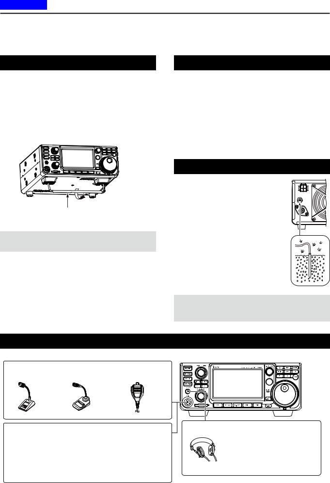
The transceiver has a stand for desktop use.
Stand
CAUTION: NEVER carry the transceiver by holding the stand, dials, controls and so on. This may damage them.
Front panel connection
Heat dissipation
••DO NOT place the transceiver against walls or put anything on top of the transceiver. This may block airflow and overheat the transceiver.
••NEVER install the transceiver in a place without adequate ventilation. Heat dissipation may be reduced, and the transceiver may be damaged. ••DO NOT touch the transceiver after transmitting
continuously for long periods of time. The transceiver may become hot.
Grounding
To prevent electrical shock, television interference (TVI), broadcast interference (BCI) and other problems, ground the transceiver using the ground terminal [GND] on the rear panel.
For best results, connect a heavy gauge wire or strap to a long ground rod. Make the distance between the [GND] terminal and ground as short as possible.
RWARNING! NEVER connect the [GND] terminal to a gas or electric pipe, since the connection could cause an explosion or electric shock.
[MIC] (Microphone) connector
SM-50 |
SM-30 |
HM-219 |
(Option) |
(Option) |
(Supplied) |
Using an External Keypad
You can control the CW memory keyer, Voice memory or RTTY memory keyer transmission from an external keypad by connecting the control circuit to the [MIC] connector. Set the external keypad settings to ON on the CONNECTORS screen to use the external keypad. (p. 12-8)
LThe external keypad is not supplied by Icom. See page 18-3 for the connector details.
[PHONES] Headphones |
Accepts headphones with 8~16 Ω impedance.
••Outputs 5 mW into an 8 Ω load.
••The volume level may differ, depending on the headphones.
2-2
Previous view
2 INSTALLATION AND CONNECTIONS
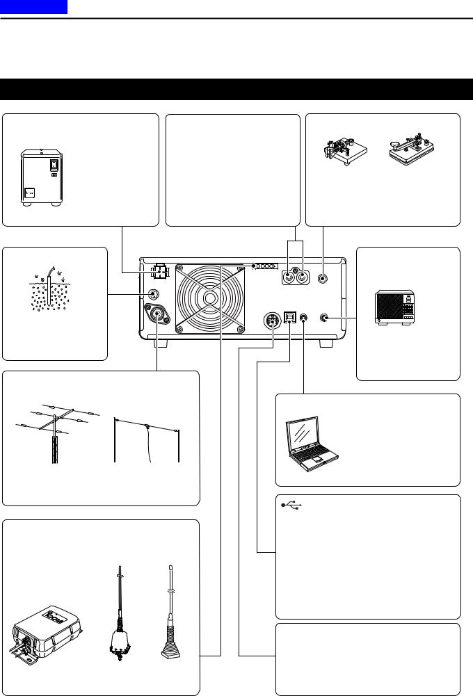
Rear panel connection
[DC 13.8 V] DC power supply |
[ALC]/[SEND] jack |
[KEY] (CW key) jack (p. 18-4) |
||
(p. 18-4) |
Connect with an RCA plug |
|
|
|
Use the optional |
[ALC] jack connects to the ALC |
|
|
|
PS-126 or a power |
|
|
||
output jack of a non-Icom linear |
|
|
||
supply with 13.8 V DC |
Paddle |
Straight key |
||
amplifier. |
||||
output and a current |
(6.35 mm: 1/4 in (d)) |
|
||
[SEND] jack is used to control |
|
|||
capacity of at least |
To use the external electronic keyer, |
|||
21 A. |
an external non-Icom linear |
select “Straight” in the “Keyer Type” |
||
|
amplifier. |
item on the CW-KEY SET screen while |
||
PS-126 (option) |
in the CW mode. |
|
[GND] (Ground) |
|
|
[EXT-SP] |
|
|
|
|
(External speaker) jack |
|
|
|
|
(p. 18-4) (3.5 mm: 1/8 in (d)) |
|
|
|
|
SP-34 |
|
|
|
|
(Option) |
|
Grounding prevents |
|
|
|
|
electrical shock, TVI |
|
|
Impedance: 4~8 Ω |
|
and other problems. |
|
|
||
|
|
Audio level: More than |
||
|
|
|
||
|
|
|
2.5 W at 10% distortion |
|
|
|
|
into an 8 Ω load |
|
[ANT] (antenna) connector |
|
|
||
|
|
|
[REMOTE] jack (p. 18-4) |
|
|
|
|
(3.5 mm: 1/8 in (d)) |
|
|
|
|
Remotely controls the |
|
|
|
|
transceiver, using the |
|
|
|
|
optional RS-BA1, or |
|
|
|
|
CI-V commands. |
|
Connect a 50 Ω antenna for the HF, 50/70 MHz |
|
|||
frequency bands. |
|
|
|
|
|
|
|
[USB] port |
|
|
|
|
••Remotely controls the transceiver using |
|
[TUNER] control socket (p. 2-4) |
|
CI-V commands. |
||
Connect the control cable |
|
|
••Sends the received audio to the PC |
|
|
|
••Inputs modulation |
||
from an optional AH-4 |
|
|
||
|
|
••Sends the decoded RTTY outputs to the PC. |
||
automatic antenna tuner |
|
|||
|
• Remote control operation using the optional |
|||
or AH-740 automatic |
|
|
RS-BA1. |
|
tuning antenna. The AH-2b |
|
|||
|
(Icom does not guarantee the performance of the |
|||
is connected to the AH-4. |
|
|
||
|
|
|
PC, network device or network settings) |
|
|
|
|
[ACC] (accessory) socket (p. 18-2) |
|
|
|
|
Connects control lines for external devices |
|
AH-4 |
AH-740 |
AH-2b |
such as a TNC or a PC. |
|
Refer to the external device’s instruction |
||||
(Option) |
(Option) |
(Option) |
||
manual for connection. |
||||
|
|
|
||
2-3

Previous view
2 INSTALLATION AND CONNECTIONS
Connecting an external DC power supply
Confirm that the transceiver is OFF before connecting the DC power cable.
LWe recommend using Icom’s optional PS-126 (DC 13.8 V/25 A) power supply.
LWhen connecting a non-Icom DC power cable, the transceiver needs:
••DC 13.8 V (Capacity: At least 21 Amps)
••A power supply with an over current protective line and low voltage fluctuation or ripple.
CAUTION: DO NOT touch the cooling fan on the rear panel of the transceiver after transmitting continuously for long periods of time. The transceiver becomes extremely hot.
PS-126 |
PS-126 |
When disconnecting, firmly |
|
q |
|
|
w |
push down the locking tab |
|
and then pull the connector |
|
|
|
|
|
|
out of the socket. |
AC cable |
DC power cable |
|
|
|
Non-Icom DC power supply
DC 13.8 V/21 A |
|
|
|
or more |
|
|
|
+ |
_ |
GND |
IC-7300 |
|
Fuses |
For European versions |
|
|
|
|
|
Red Black |
|
|
|
|
Supplied DC |
|
|
|
power cable |
|
|
|
|
Connect to |
|
|
|
power supply |
|
Connecting the antenna tuner
The AH-4 matches the IC-7300 to the optional AH-2b or a long wire antenna more than 7 m/23 ft long (between 3.5 MHz and 50 MHz).
NOTE: Before connecting, be sure to turn OFF the transceiver power.
LSee the AH-4 instruction manual for installation and connection details.
[ANT] |
|
HF band long wire |
[TUNER] |
|
antenna |
|
AH-4 |
|
IC-7300 |
|
Or to an optional AH-2b |
GND |
GND |
|
|
|
|
Control cable |
|
|
|
|
2-4 |
Previous view
2 INSTALLATION AND CONNECTIONS
FSK and AFSK connections
The transceiver has a mode key for RTTY. You can use a PC and an application software to operate RTTY using a USB cable. However, if you want to operate RTTY or other digital modes, you can use the ACC socket on the rear panel through an interface unit. Refer to the software application’s instruction manual for setup details.
(Icom does not guarantee performance of the application software, PC, network device or network settings.)
(1) When using the USB port
Type B |
|
|
|
|
IC-7300 |
To a USB port |
|
To the |
|
|
|
|
|
PC |
|
USB port |
|
|
|
|
|
|
|
|
|
|
Install the RTTY |
|
A user supplied A/B USB cable |
Type A |
application software |
|
|
TIP:
••If you set the “USB Serial Function” item to “RTTY Decode,” the decoded RTTY signals are output from the USB port.
MENU » SET > Connectors > USB Serial Function
••You can download the USB driver and the installation guide from the Icom website. http://www.icom.co.jp/world/index.html
(Support > Firmware Updates/Software Downloads > Transceiver)
(2) When using the ACC socket or the microphone connector |
|
Interface circuit |
|||||||||||
|
|
|
|
|
|
|
|
|
|
|
|
|
example for digital |
••When connecting to [ACC] |
|
|
2 kΩ 2 kΩ |
10 kΩ |
|
Shield cable |
modes |
||||||
|
|
|
(User supplied) |
||||||||||
|
|
|
|
|
|
|
|
10 kΩ |
|
|
|
||
|
|
|
|
|
|
|
|
|
|
|
Connect to |
||
ACC |
|
|
|
|
|
|
(Trimpot) |
|
|
|
|||
|
|
E |
|
|
|
|
|
|
LINE IN or |
||||
|
SQL |
|
|
|
|
|
|
|
|
||||
|
|
|
Shield cable |
|
|
|
|
|
|
|
|
MIC IN |
|
|
|
|
D |
D |
|
|
|
|
|
|
|
|
|
|
|
|
|
|
2 kΩ 2 kΩ |
Shield cable |
|
|
|
||||
|
!3 |
E |
C |
|
|
|
|
No connection |
|||||
o !0!1!2 |
A |
|
|
|
|
|
|
|
|
|
|||
t y u i |
••ACC:Connect to [C] |
|
|
|
10 kΩ |
10 kΩ |
|
|
|
||||
q w e r |
B |
|
|
|
|
|
Connect to |
||||||
|
|
|
••MIC: Connect to [F] |
|
|
|
(Trimpot) |
|
|
|
|||
|
|
|
|
|
|
|
|
|
|
|
|
SP OUT |
|
|
|
|
|
|
|
|
|
|
|
|
|
|
|
|
|
|
C |
B |
|
|
|
|
|
|
|
|
|
|
|
|
|
|
*1 |
|
|
|
|
|
No connection |
||
(Rear panel view) |
A |
|
|
|
Shield cable |
|
|||||||
|
|
|
|
|
|
|
|
|
|
|
|
||
|
|
|
|
E |
C |
B |
4.7 kΩ |
*2 |
RTS |
D-Sub 25 |
D-Sub 9 |
|
|
|
|
|
|
|
|
|
Pin 4 |
Pin 7 |
|
||||
|
|
|
|
|
|
|
|
|
|
|
|||
|
|
|
|
|
|
|
|
|
|
GND |
|
||
••When connecting to [MIC] |
|
|
|
|
|
Pin 7 |
Pin 5 |
PC |
|||||
|
|
*1 |
|
|
|
|
|
Connect to |
|||||
|
|
|
|
|
|
|
|
|
|
|
|
||
|
|
|
D |
|
|
|
|
|
|
|
|
COM port |
|
|
|
|
|
|
|
|
|
|
|
|
|
LSee pages 18-2 to |
|
|
|
|
E |
|
E |
C |
B 4.7 kΩ |
|
|
|
|
|
|
1 |
|
7 |
F |
|
|
*2 |
TXD |
Pin 2 |
Pin 3 |
18-3 for details on |
|||
2 |
8 |
6 |
C |
|
|
|
|
|
|
|
the ACC socket and |
||
3 |
4 |
5 |
B |
|
|
|
|
|
|
Shield cable |
|
MIC connector. |
|
|
|
|
|
|
|
|
|
|
|
|
|
||
(Front panel view) |
*1 |
NPN transistor |
*2 Switching diode |
|
|||
NOTE: You can operate |
|
(2SC1815) |
(1S1588) |
|
|
|
|
ONLY AFSK RTTY when |
|
The sections shown in short dashes are required only when Baudot RTTY is used in the FSK (RTTY) mode. |
|
you connect the circuit to |
|
(Not required for other digital modes such as SSTV or PSK) |
|
the microphone connector. |
|
|
|
2-5

Previous view
2 INSTALLATION AND CONNECTIONS
Linear amplifier connections
DDConnecting the IC-PW1/IC-PW1EURO
See the illustration below to connect the optional IC-PW1 or IC-PW1EURO hf/50 mhz all band 1 kw linear amplifier.
Refer to the amplifier’s instruction manual for operation.
To an |
|
Remote control cable |
|
|
|
|
|
|
|
antenna |
[ACC-1] |
ACC cable |
7-pin side |
|
[ANT] |
[REMOTE] |
OPC-599 conversion cable |
|
|
|
|
Coaxial cable |
[ACC] |
[REMOTE] |
|
|
[INPUT 1] |
|
|
|
|
GND |
|
|
|
EXCITER |
|
|
|
|
1 |
1&2 |
IC-7300 |
|
|
|
|
[ANT] |
|
|
IC-PW1/IC-PW1EURO |
GND |
|
|
|
|
|
|
|
AC outlet |
|
|
|
|
Non-European versions: 100~120/200~240 V |
|
|
||
European version: |
230 V |
|
|
|
DDConnecting a non-Icom linear amplifier
See the illustration below to connect a non-Icom linear amplifier.
LWe recommend that you use a linear amplifier with a specified input power of 100 watts or more. If you use an amplifier with a specified drive level of less than 100 watts, adjust the IC-7300’s output power to the specified level before transmitting. Otherwise the linear amplifier may be damaged.
To an antenna |
|
|
|
Non-Icom linear amplifier |
[ALC] |
[SEND] |
|
RF OUT |
RF IN |
|
|
|
ALC |
|
|
|
SEND |
|
|
|
|
IC-7300 |
|
|
|
GND |
|
|
|
[ANT] |
|
R WARNING!
••The maximum signal level of the [SEND] jack is 16 V/0.5 A DC. Use an external unit if your non-Icom linear amplifier requires a control voltage and/or current greater than specified.
••The ALC input level must be in the range 0 to –4 V. The transceiver does not accept a positive voltage. Non-matched ALC and RF power settings could overheat or damage the linear amplifier.
••When using a linear amplifier such as the IC-PW1 or IC-PW1EURO, set the RF POWER in the Multi-function menu to keep the ALC meter in the red zone.
LSee page 3-10 for details on the RF POWER
LSee page 3-11 for details on the ALC zone.
2-6
Previous view |
|
|
|
Section 3 |
BASIC OPERATION |
|
|
|
|
When first applying power....................................................... |
3-2 |
|
|
Turning power ON or OFF...................................................... |
3-2 |
|
|
Adjusting the volume level...................................................... |
3-2 |
|
|
About the VFO and Memory modes........................................ |
3-2 |
|
|
Using the VFO mode............................................................... |
3-2 |
|
|
DDSelecting VFO A or VFO B.............................................. |
3-2 |
|
|
DDEqualizing VFO A and VFO B.......................................... |
3-2 |
|
|
Selecting the operating band.................................................. |
3-3 |
|
|
DDUsing the band stacking registers................................... |
3-3 |
|
|
Selecting the operating mode................................................. |
3-3 |
|
|
Setting the frequency.............................................................. |
3-4 |
|
|
DDUsing the Main Dial......................................................... |
3-4 |
|
|
DDAbout the Tuning Step function....................................... |
3-4 |
|
|
DDChanging the Tuning Step............................................... |
3-4 |
|
|
DDAbout the 1 Hz step Fine Tuning function....................... |
3-4 |
|
|
DDAbout the 1/4 Tuning function.......................................... |
3-5 |
|
|
DDAbout the Auto Tuning Step function............................... |
3-5 |
|
|
DDDirectly entering a frequency........................................... |
3-5 |
|
|
DDBand Edge Beep............................................................. |
3-6 |
|
|
DDEntering a Band Edge..................................................... |
3-7 |
|
|
RF gain and SQL level.......................................................... |
3-10 |
|
|
Dial Lock function.................................................................. |
3-10 |
|
|
Basic transmission................................................................ |
3-10 |
|
|
Adjusting the transmit output power...................................... |
3-10 |
|
|
DDAdjusting the transmit output power.............................. |
3-10 |
|
|
Meter display.......................................................................... |
3-11 |
|
|
DDMeter display selection................................................... |
3-11 |
|
|
DDMulti-function meter........................................................ |
3-11 |
|
|
Adjusting the microphone gain............................................... |
3-11 |
|
|
About the 5 MHz frequency band |
|
|
|
operation (USA version only)............................................ |
3-12 |
3-1

Previous view
3 BASIC OPERATION
When first applying power
Before turning ON your transceiver for the first time, make sure all of the following are correctly connected. ••DC power cable
••Antenna ••Grounding wire ••Microphone*
*Different devices may be used, depending on the operating mode.
If all listed above are correctly connected, set AF
 RF/SQL (inner/outer) to the positions described below.
12 oʼclock position (outer) 

 Maximum counterclockwise (inner)

TIP: When you turn OFF the transceiver, it memorizes the current settings. Therefore, when you turn ON the transceiver again, the it restarts with the same settings.
Turning power ON or OFF
zzTo turn ON the transceiver, push  zzTo turn OFF the transceiver, hold down
2 seconds until “POWER OFF...” is displayed.
Adjusting the volume level
Rotate AF
 RF/SQL (inner) to adjust the volume level.
About the VFO and Memory modes
VFO mode
You can set the desired frequency by rotating MAIN DIAL .
Memory mode
You can enter contents into the memory channels in the MEMORY list.
Selecting the VFO mode or Memory mode
Push V/M to select the VFO or Memory mode.
|
|
|
V/M |
|
|
|
|
|
|
||
VFO |
|
mode |
Memory |
|
mode |
|
|
||||
(Example: VFO A) |
(Example: Memory channel 1) |
||||
Using the VFO mode
The IC-7300 has 2 Variable Frequency Oscillators (VFO), “A” and “B.” Having 2 VFOs is convenient to quickly select 2 frequencies, or for split frequency operation (p. 4-13). You can use either of the VFOs to operate on a frequency and mode.
DDSelecting VFO A or VFO B
Push A/B to select the VFO A or VFO B.
A/B
VFO A |
VFO B |
DDEqualizing VFO A and VFO B
You can set the displayed VFO’s frequency and mode to the VFO that is not displayed.
Hold down A/B until 2 short beeps sound.
3-2

Previous view
3 BASIC OPERATION
Selecting the operating band
Do the following steps to change the operating band. Also, the band stacking register provides 3 memories for each band key to store frequencies and operating modes. This function is convenient to quickly recall previously operated frequencies and modes.
Selecting the operating mode
You can select between the SSB, SSB data, CW, CW reverse, RTTY, RTTY reverse, AM, AM data, FM and FM data modes.
1. Touch the mode icon (example: USB).
DDUsing the band stacking registers
Follow the steps below to enter a register on the selected band. (Example: Memorizing 21 MHz)
1.Touch the MHz digits. (Example: 14)
••Opens the BAND STACKING REGISTER screen.
2.Touch a band key. (Example: [21])
BAND STACKING REGISTER screen ••Displays a 21 MHz frequency.
TIP: Selecting a different Register
LTouching the band key for 1 second changes between the 3 Registers.
LTouch to return to the previous screen.
3.Set the frequency and the operating mode. (Example: 21.30000 MHz in the USB mode)
4.Touch the MHz digits again.
LThe frequency and operating mode set in step 3 is memorized in the top Register.
5.By repeating the steps above, the Register that a new frequency and operating mode are set in is memorized.
2.In the MODE screen, touch the desired mode key. (Example: CW).
LIn the SSB, AM or FM modes, the [DATA] key is displayed.
MODE screen
••Operating mode selection list
LTouch mode key to select the operating mode
Mode key |
Operating mode |
||
[SSB] |
LSB |
USB |
|
[CW] |
CW |
CW-R |
|
[RTTY] |
RTTY |
RTTY-R |
|
[AM] |
|
AM |
|
[FM] |
|
FM |
|
|
LSB |
LSB-D |
|
[DATA] |
USB |
USB-D |
|
AM |
AM-D |
||
|
|||
|
FM |
FM-D |
|
Selecting the Data mode
You can operate RTTY in the data mode using AFSK (Audio Frequency Shift Keying). (p. 4-31)
LWhen a data mode is selected, you can mute the input from the microphone. (p. 12-8)
MENU » SET > Connectors > DATA MOD
(Example: selecting the USB-D mode)
1.While the USB mode is selected, touch the mode icon.
••Opens the MODE screen.
2.Touch [DATA].
MODE screen
••The USB-D mode is selected.
3-3

Previous view
3 BASIC OPERATION
Setting the frequency
DDUsing the Main Dial
1.Select the desired operating band. (Example: 21 MHz)
BAND STACKING REGISTER screen
2.Rotate MAIN DIAL .
LIf you cannot change the frequency, make sure the Dial Lock function is turned OFF. (p. 3-10)
L is displayed when you set an amateur radio frequency, and
  is displayed when you set a frequency outside the Ham band, or outside your set Band Edges.
DDAbout the Tuning Step function
You can set the MAIN DIAL ’s tuning step for each operating mode. The following steps are set as default.
••SSB/CW/RTTY (TS OFF): 10 Hz
••AM (TS ON): |
1 kHz |
••FM (TS ON): |
10 kHz |
Touch the kHz digits to turn the Tuning Step function ON or OFF.
L The Tuning Step function's icon “▼” is displayed above the 1 kHz digit.
The Tuning Step function is ON.
DDChanging the Tuning Step
When the Tuning Step function is ON, you can change the tuning steps for each operating mode.
1.Select the desired operating mode. (p. 3-3) (Example: USB)
2.Touch the kHz digit for 1 second.
••The TS (SSB) screen is displayed.
3.Touch the desired tuning step. (Example: 0.1 k)
••The tuning step is set and returns to the previous screen.
The Tuning
Step function is
ON.
TS (SSB) screen
DDAbout the 1 Hz step Fine Tuning
function
You can use the minimum tuning step of 1 Hz for fine tuning in the SSB, CW and RTTY modes.
Touch the Hz digits for 1 second to turn the Fine Tuning function ON or OFF.
••The 1 Hz digit is displayed.
 1Hz digit
LWhen using the [UP]/[DN] keys on the microphone, the frequency changes in 50 Hz steps with the Fine Tuning function ON or OFF.
3-4

Previous view
3 BASIC OPERATION
Setting the frequency (Continued)
DDAbout the 1/4 Tuning function
Mode: SSB-D/CW/RTTY
With the Tuning Function OFF, turn ON the 1⁄4 Tuning function to reduce the tuning speed to 1⁄4 of the normal speed, for finer tuning.
1.Push FUNCTION .
••Opens the FUNCTION screen.
2.Touch [1/4].
FUNCTION screen
3. Push EXIT .
 1/4 Tuning
function
DDAbout the Auto Tuning Step function
The tuning step automatically changes, depending on the rotation speed of MAIN DIAL .
LYou can change the Auto Tuning Step function settings in the following menu. (p. 12-6)
MENU » SET > Function > MAIN DIAL Auto TS
DDDirectly entering a frequency
You can set the frequency without rotating MAIN DIAL by directly entering it on the keypad.
Entering the operating frequency
1.Touch the MHz digits. (Example: 14)
••Opens the BAND STACKING REGISTER screen.
2.Touch [F-INP].
BAND STACKING REGISTER screen ••Opens the F-INP screen.
3.Start entry with the MHz digits.
LTo clear the entry, touch [CE].
LTo clear the entry and return to the previous screen, push EXIT .
F-INP screen (Example:14.025)
4.Touch [ENT] to set the entered frequency.
••Closes the F-INP screen.
LIf you touch [ENT] when the digits under 100 kHz are not entered, “0” will be automatically entered into the digits that are blank.
Entry examples
••14.025 MHz: |
[1], [4], [•(−)], [0], [2], [5], [ENT] |
••18.0725 MHz: |
[1], [8], [•(−)], [0], [7], [2], [5], [ENT] |
••730 kHz: |
[0], [•(−)], [7], [3], [ENT] |
••5.100 MHz: |
[5], [•(−)], [1], [ENT] |
••7.000 MHz: |
[7], [ENT] |
••Changing from 21.280 MHz to 21.245 MHz: [•(−)], [2], [4], [5], [ENT]
3-5

Previous view
3 BASIC OPERATION
Setting the frequency (Continued)
Entering the Split Frequency Offset
1.Touch the MHz digits. (Example: 14)
••Opens the BAND STACKING REGISTER screen.
2.Touch [F-INP].
Entering a Memory channel
1. Touch V/M to select the Memory mode.
VFO |
|
V/M |
|
|
|
|
|
mode |
Memory mode |
||
(Example: VFO A) |
(Example: Memory channel 1) |
||
2.Touch the MHz digits. (Example: 14)
BAND STACKING REGISTER screen ••Opens the F-INP screen.
3.Enter the Split Frequency Offset.
LIf you want the minus shift direction, touch [•(−)]. LEnter the offset between −9.999 MHz and +9.999
MHz (1 kHz steps).
 [SPLIT] or [-SPLIT] is displayed
F-INP screen
Touch for -Split
4.To save the entry, touch [SPLIT] or [−SPLIT].
••Closes the F-INP screen.
Entry examples
••10 kHz: |
[1], [0], [SPLIT] |
••−1.025 MHz: |
[•(−)], [1], [0], [2], [5], [−SPLIT] |
LAfter entering, the Split function is automatically turned ON.
••Opens the BAND STACKING REGISTER screen.
3. Touch [F-INP].
BAND STACKING REGISTER screen ••Opens the F-INP screen.
4. Enter a Memory channel number between 1 and
99. (Memory channel 5)
LIf you want to set the Program Channel number (P1 or P2), enter “100” for P1, and “101” for P2.
F-INP screen
5.Touch [MEMO] to select the entered channel.
••Closes the F-INP screen.
DDBand Edge Beep
You will hear a Band Edge Beep and  will be displayed when you tune into or out of an amateur band’s frequency range.
LYou can change the Band Edge Beep settings in the following menu.
MENU » SET > Function > Band Edge Beep
3-6

Previous view
3 BASIC OPERATION
Setting the frequency (Continued)
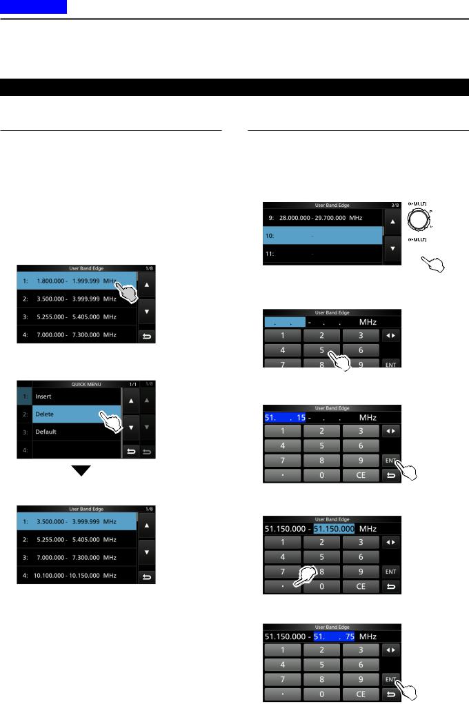
DDEntering a Band Edge
When “ON (User)” or “ON (User) & TX Limit” is selected on the “Band Edge Beep” screen, you can enter a total of 30 band edge frequencies.
LInitially, all band edges are entered. Therefore, you must first edit or delete them to enter a new band edge.
LYou cannot enter an overlapped frequency or a frequency that is out of the preset transmit frequency.
1. Open the “Band Edge Beep” screen.
MENU » SET > Function > Band Edge Beep
2.Select “ON (User)” or “ON (User) & TX Limit.”
LIf you select “ON (User) & TX Limit,” you can limit transmission to within the entered frequency range.
 Rotate
 Push
Push
“Band Edge Beep” screen
3. Select “User Band Edge.”
 Rotate
 Push
Push
FUNCTION set screen ••Opens the “User Band Edge” screen.
Editing a Band Edge
You can edit a band edge entered as a default or when entering a new band edge.
1.On the FUNCTION set screen, select “User Band Edge.”
2.Touch the band edge you want to edit for 1 second.
(Example: 5: 14.000.000 – 14.350.000 MHz)
 Rotate
 Push
Push
“User Band Edge” screen
3.Edit the lower band edge frequency. (Example: 14.1)
Entry examples
••14.025 MHz: |
[1], [4], [•], [0], [2], [5], [ENT] |
••18.0725 MHz: |
[1], [8], [•], [0], [7], [2], [5], [ENT] |
••730 kHz: |
[0], [•], [7], [3], [ENT] |
••5.100 MHz: |
[5], [•], [1], [ENT] |
••7.000 MHz: |
[7], [ENT] |
••Changing from 21.280 MHz to 21.245 MHz: [•], [2], [4], [5], [ENT]
4.Touch [ENT] to save the edited lower band edge frequency.
5.Edit the upper band edge frequency. (Example: 14.25)
6.Touch [ENT] to save the edited upper band edge frequency.
LThe edited band edge is saved and returns to the previous screen.
TIP:
••You can also edit the frequency by rotating MAIN DIAL or MULTI .
••Each band edge must be higher in frequency than the ones above it. If you try to enter a lower frequency than the edges above, the lower frequency edge will be cleared when you push [ENT].
3-7
Previous view
3 BASIC OPERATION
Setting the frequency
DDEntering a Band Edge (Continued)
Deleting a Band Edge
To enter a new band edge, first you must delete a preset band edge.
LInitially, all band edges are entered. Therefore, you must first edit or delete them to enter a new band edge.
LYou cannot enter an overlapped frequency or a frequency that is out of the preset transmit frequency.
1.On the FUNCTION set screen, select “User Band Edge.”
2.Touch the desired band edge to delete for 1 second.
(Example: 1: 1.800.000 – 1.999.999 MHz)
“User Band Edge” screen
3. Touch “Delete.”
••The selected band edge is deleted and returns to the previous screen.
1.800.000 – 1.999.999 MHz is deleted.
Entering a new Band Edge
After you delete or edit the preset band edges, you can enter a new band edge.
1.Open the “User Band Edge” screen.
2.Select a blank band. (Example: 10)
 Rotate
 Push
Push
“User Band Edge” screen
3.Enter the lower band edge frequency. (Example: 51.15)
4.Touch [ENT] to save the entered lower band edge frequency.
5.Enter the upper band edge frequency. (Example: .75)
6.Touch [ENT] to save the entered upper band edge frequency.
••The entered band edge is saved and returns to the previous screen.
3-8
Loading...