


INSTRUCTION MANUAL
245 MHz FM TRANSCEIVER
i3FGX
P0 
 P1
P1 

 P2
P2 


 P3
P3 

1 


 2
2 


 3
3
4 |
5 |
6 |
7 

 8
8 

 9
9
0

FOREWORD
Thank you for purchasing the IC-3FGX 245 MHz FM transceiver. READ ALL INSTRUCTIONS carefully and completely before using the transceiver.
SAVE THIS INSTRUCTION MANUAL–This instruction manual contains important operating instructions for the transceiver.
IMPORTANT
RCAUTION! NEVER hold the transceiver so that the antenna is very close to, or touching exposed parts of the body, especially the face or eyes, while transmitting. The transceiver will perform best if the microphone is 2 to 4 in. (5 to 10 cm) away from the lips and the transceiver is vertical.
RCAUTION! NEVER operate the transceiver with a headset or other audio accessories at high volume levels.
RCAUTION! NEVER short the terminals of the battery pack.
DO NOT push the PTT when not actually desiring to transmit.
AVOID using or placing the transceiver in direct sunlight or in areas with temperatures below +14°F (–10°C) or above +122°F (+50°C).
DO NOT modify the transceiver for any reason.
KEEP the transceiver from the heavy rain, and Never immerse it in the water. The transceiver construction is water resistant, not water proof.
The use of non-Icom battery packs/chargers may impair transceiver performance and invalidate the warranty.
i

TABLE OF CONTENTS
FOREWORD . . . . . . . . . . . . . . . . . . . . . . . . . . . . . . . . . . . . . . . . . . .i IMPORTANT . . . . . . . . . . . . . . . . . . . . . . . . . . . . . . . . . . . . . . . . . . .i TABLE OF CONTENTS . . . . . . . . . . . . . . . . . . . . . . . . . . . . . . . . . .ii
1 PANEL DESCRIPTION . . . . . . . . . . . . . . . . . . . . . . . . . . . . . .1–3
‘ Switches, controls, keys and connectors . . . . . . . . . . . . . . .1–2 ‘ Function display . . . . . . . . . . . . . . . . . . . . . . . . . . . . . . . . . . . .3
2 ACCESSORIES . . . . . . . . . . . . . . . . . . . . . . . . . . . . . . . . . . . . . .4 3 BATTERY PACKS . . . . . . . . . . . . . . . . . . . . . . . . . . . . . . . . .5–10
‘ Battery pack replacement . . . . . . . . . . . . . . . . . . . . . . . . . . . .5 ‘ Battery cautions . . . . . . . . . . . . . . . . . . . . . . . . . . . . . . . . . . . .6 ‘ Battery charging . . . . . . . . . . . . . . . . . . . . . . . . . . . . . . . . . .7-8 ‘ Charging NOTE . . . . . . . . . . . . . . . . . . . . . . . . . . . . . . . . . . .9 ‘ Battery case (Option) . . . . . . . . . . . . . . . . . . . . . . . . . . . . . .10
4 PROGRAMMABLE FUNCTIONS . . . . . . . . . . . . . . . . . . . . .11-15
‘ Receiving and transmitting . . . . . . . . . . . . . . . . . . . . . . . . . . .11
5 CONVENTIONAL OPERATION . . . . . . . . . . . . . . . . . . . . . .16-18
‘ Call procedure . . . . . . . . . . . . . . . . . . . . . . . . . . . . . . . . . . . .17 ‘ Tx code channel selection . . . . . . . . . . . . . . . . . . . . . . . . . . .18
‘ Manual 5-tone codes . . . . . . . . . . . . . . . . . . . . . . . . . . . . . . .18 ‘ Transmitting notes . . . . . . . . . . . . . . . . . . . . . . . . . . . . . . . . .18
6 OTHER FUNCTIONS . . . . . . . . . . . . . . . . . . . . . . . . . . . . . . . . .19
‘ DTMF pager/Code squelch . . . . . . . . . . . . . . . . . . . . . . . . . .19
7 MAINTENANCE . . . . . . . . . . . . . . . . . . . . . . . . . . . . . . . . . . . . .20
‘ Optional UT-108/UT-109 and UT-110 installation . . . . . . . . .20
8 CLONING . . . . . . . . . . . . . . . . . . . . . . . . . . . . . . . . . . . . . . . . . .21 9 CHANNEL LIST . . . . . . . . . . . . . . . . . . . . . . . . . . . . . . . . . . . . .22 10 SPECIFICATIONS . . . . . . . . . . . . . . . . . . . . . . . . . . . . . . . . . .23 11 OPTIONS . . . . . . . . . . . . . . . . . . . . . . . . . . . . . . . . . . . . . . .24-25 12 MEMO . . . . . . . . . . . . . . . . . . . . . . . . . . . . . . . . . . . . . . . . .26-28
ii
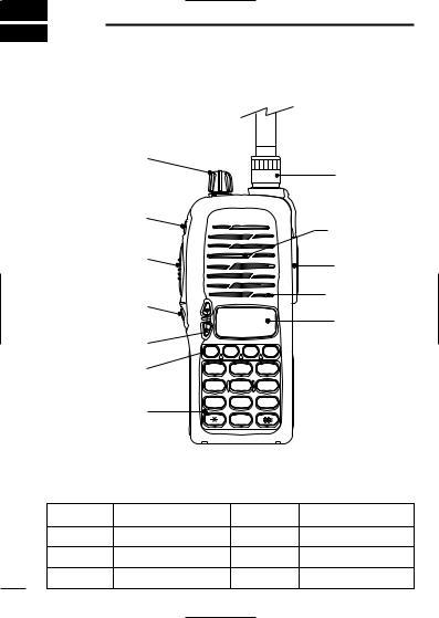
1 PANEL DESCRIPTION
‘ Switches, controls, keys and connectors
q |
|
|
|
|
|
|
i |
w |
|
|
Speaker |
|
|
|
|
e |
|
|
o |
|
|
|
|
r |
|
|
Mic |
|
|
|
|
|
|
|
!0 |
t |
P0 |
P1 P2 |
P3 |
|
|||
y |
1 |
2 |
3 |
|
4 |
5 |
6 |
u |
7 |
8 |
9 |
|
0 |
|
|
|
|
|
|
D Programmable key reference |
|
|
|
S1 (Red) |
|
P0 |
|
S2 (Black) |
|
P1 |
|
Y |
|
P2 |
|
Z |
|
P3 |
|
1

PANEL DESCRIPTION 1
q VOLUME CONTROL [OFF/VOL]
Turns power ON and adjusts the audio level. w DEALER-PROGRAMMABLE KEY [S1 (Red)] e PTT SWITCH [PTT]
Push and hold to transmit; release to receive. r DEALER-PROGRAMMABLE KEY [S2(Black)]
tUP/DOWN KEYS [Y]/[Z]
•Push to select the operating channel.
y DEALER-PROGRAMMABLE KEYS [P0]/[P1]/[P2]/[P3]
Can each be programmed for one of several functions by your Icom Dealer.
u 10-KEY PAD
Used to enter DTMF codes, the operating channel, etc. i ANTENNA CONNECTOR (BNC)
Connects the supplied antenna. o [SP]/[MIC] JACK
Connect optional speaker-microphone.
!0FUNCTION DISPLAY
Displays the following information:
•CH number.
•5-tone indication.
•Low-battery indication.
•DTMF numbers.
•Low-power indication.
•Skip-Ch indication.
•Audible indication.
NOTE: Above functions depend on pre-setting.
2
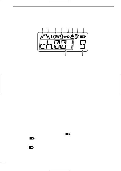
1 PANEL DESCRIPTION
‘ Function display
q w e r t y u i
!0 o
q TRANSMIT INDICATOR
Appears during PTT on. w BUSY INDICATOR
Appears while receiving a signal or when the squelch is open. e LOW POWER INDICATOR (p. 12)
Appears when low output power is selected. r SCRAMBLER INDICATOR
Appears while the scrambler function is operating. t KEY LOCK INDICATOR (p. 11)
Appears during key lock function ON. y BELL INDICATION
Appears or blinks when the optional 5Tone call is received. u AUDIBLE INDICATOR
Appears when monitor function is turned ON. (CTCSS and DTCS mutes are released.)
i LOW BATTERY INDICATOR [ |
] |
|
-When |
appears, battery |
|
capacity is low and transmitting is impossible. |
||
-When |
flashes, battery capacity is nearly exhausted. |
|
o S-meter |
|
|
Show the received signal strength
!0ALPHANUMERIC INDICATOR
3
ACCESSORIES 2
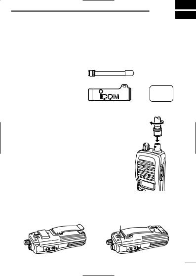
‘ Accessory attachment
D Supplied accessories
The transceiver comes supplied with the following accessories.
q Flexible antenna
w Belt clip
q
e 2251 OPT sheet
(See p. 26)
w e
D Antenna
The antenna screws onto the transceiver as illustrated right.
Keep the jack cover attached when jacks are not in use to avoid bad contacts.
D Belt clip
Attach the belt clip to the transceiver as illustrated below.
To attach the belt-clip |
To release the belt-clip |
4
3 BATTERY PACKS
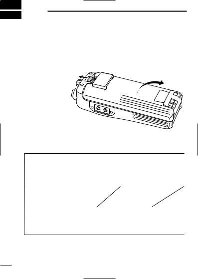
‘ Battery pack replacement
Before replacing the battery pack, the volume control MUST be rotated fully counterclockwise, until a click is heard, to turn the power OFF.
• Push the battery release forward, then pull the battery pack upward with the transceiver facing you.
D BATTERY PACKS
|
|
|
Charging period |
|
||
Battery |
|
|
|
|
Operating |
|
Voltage |
Capacity |
|
BC-119 or |
|||
pack |
|
|
BC-137 |
BC-121 |
period*1 |
|
|
|
|
|
|||
|
|
|
|
with AD-94 |
|
|
BP-208 |
Battery case for AA |
|
N/A |
|
||
(R6) × 6 alkaline |
|
|
||||
|
|
|
|
|
|
|
BP-209R |
7.2 V |
1100 |
15 hrs |
1.5 hrs |
8 hrs |
|
mAh |
||||||
|
|
|
|
|
||
BP-210 |
7.2 V |
1650 |
15 hrs |
2.0 hrs |
11 hrs |
|
mAh |
||||||
|
|
|
|
|
||
|
|
|
|
|
|
|
*1 Operating periods are calculated under the following conditions; Tx : Rx : standby =5 : 5 : 90
* Operating period depends on alkaline cells used.
5

BATTERY PACKS 3
‘Battery cautions
•CAUTION! NEVER short terminals of the battery pack (or charging terminals of the transceiver). Also, current may flow into nearby metal objects such as a necklace, so be careful when placing battery packs (or the transceiver) in handbags, etc.
Simply carrying with or placing near metal objects such as a necklace, etc. causes shorting. This will damage not only the battery pack, but also the transceiver.
•NEVER incinerate used battery packs. Internal battery gas may cause an explosion.
•NEVER immerse the battery pack in water. If the battery pack becomes wet, be sure to wipe it dry BEFORE attaching it to the transceiver.
•Clean the battery terminals to avoid rust or miss contact.
•Keep battery contacts clean. It’s a good idea to clean battery terminals once a week.
If your battery pack seems to have no capacity even after being charged, completely discharge it by leaving the power ON overnight. Then, fully charge the battery pack again. If the battery pack still does not retain a charge (or only very little charge), a new battery pack must be purchased. (P. 9)
6
3 BATTERY PACKS
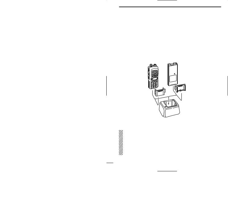
‘ Battery charging
D Rapid charging with the BC-119+AD-94
The optional BC-119 provides rapid charging of optional battery packs.
The following are additionally required:
•One AD-94.
•An AC adapter (may be supplied with the BC-119 depending on version).
Turn power
OFF.
Check orientation for correct charging. (Insert together with AD-94.)
AD-94
AD-94
BC-119
When using the BC-119 in a vehicle: If the charge indicator flashes orange, the vehicle battery voltage is low and charging may not be performed. Check the vehicle battery voltage in this case. If the charge indicator flashes red, there may be a problem with the battery pack (or charger). Re-insert the battery pack or contact your dealer.
7
 Loading...