


DOC. NO HHIS-WZ-PK-008 (02)
Accredited by the RvA
ISO 9001/ISO 14001/OHSAS 18001(N/A)
REGISTERED FIRM
DNV Certification B.V., THE NETHERLANDS
 RUN
RUN
plus
VECTOR INVERTER
INSTRUCTION MANUAL
plus
CONTENTS
Page
1. Safety Message
2. Receiving and Checking
3. General Specifications
4. External dimensional diagrams and Identifying the parts
5. Mounting
6. Wiring
7. Operation
8. Using Intelligent Input Terminals
9. Function List
10. Protective functions
11. Trouble shooting Tips
12. Maintenance and Inspection
13. Option
plus
1. Safety Messages
For the best results with the N100plus Series inverter, carefully read this manual and all of the warning labels attached to the inverter before installing and operating it, and follow the instructions exactly. Keep this manual handy for quick reference.
Definitions and Symbols
A safety instruction(message) includes a hazard alert symbol and a signal word, DANGER or CAUTION. Each signal word has the following meaning:
This symbol is the "Safety Alert Symbol." It occurs with either of two signal words : DANGER or CAUTION, as described below
DANGER : Indicates a potentially hazardous situation which, if not avoided, can result in serious injury or death.
CAUTION : Indicates a potentially hazardous situation which, if not avoided, can result in minor to moderate injury, or serious damage to the product. The situation described in the CAUTION may, if not avoided, lead to serious results. Important safety measures are described in CAUTION (as well as DANGER), so be sure to observe them.
NOTE : Notes indicate an area or subject of special merit, emphasizing either the product's capabilities or common errors in operation or maintenance.
plus
 CAUTION
Some drawings in this manual are shown with the protective or shields removed in order to describe detail with more clarity. Make sure all covers and shields are replaced before operating this product.
This manual may be modified when necessary because of the improvement of the product, modification, or changes in specifications.
To order a copy of this manual, or if your copy has been
damaged or lost, contact your 


 representative.
Hyundai is not responsible for any modification of the product made by the user, since that will void the guarantee.
plus
Index to Dangers and Cautions in This Manual
Installation-cautions for Mounting Procedures
 CAUTION
Be sure to install the unit on flame-resistant |
5-1 |
material such as a steel plate. |
|
Otherwise, there is the danger of fire. |
|
Be sure not to place any flammable materials |
5-1 |
near the inverter. |
|
Otherwise, there is the danger of fire. |
|
Be sure not to let the foreign matter enter vent |
5-1 |
openings in the inverter housing, such as wire |
|
clippings, spatter from welding, metal shavings, dust, etc. |
|
Otherwise, there is the danger of fire. |
|
Be sure to install the inverter in a place which can |
5-1 |
bear the weight according to the specifications in the text. |
|
Otherwise, it may fall and cause injury to personnel. |
|
Be sure to install the unit on a perpendicular wall |
5-1 |
which is not subject to vibration. |
|
Otherwise, it may fall and cause injury to personnel. |
|
Be sure not to install or operate an inverter which |
5-1 |
is damaged or has missing parts. |
|
Otherwise, it may cause injury to personnel. |
|
Lift the cabinet by the cooling fin. When moving the |
5-1 |
unit, never lift by the plastic case or the terminal covers. |
|
Otherwise, the main unit may be dropped causing damage |
|
to the unit. |
|
When mounting units in an enclosure, install a fan or |
5-1 |
other cooling device to keep the intake air temperature |
|
below 40 .
.
plus
 CAUTION
Be sure to maintain the specified clearance |
5-2 |
area around the inverter and to provide adequate |
|
ventilation. |
|
Otherwise, the inverter may overheat and cause eguipment |
|
damage or fire. |
|
Be sure to install the inverter in a well-ventilated |
5-2 |
room which does not have direct exposure to |
|
sunlight, a tendency for high temperature, high |
|
humidity of dew condensation, high levels of dust, corrosive gas, explosive gas, inflammable gas, grinding-fluid mist, salt damage, etc.
Otherwise, there is the danger of fire.
plus
Wiring-Dangers for Electrical Practices and Wire Specifications
 DANGER
Be sure to connect grounding terminal.
Otherwise, there is a danger of electric shock and/or fire.
Wiring work shall be carried out only by qualified personnel.
Otherwise, there is a danger of electric shock and/or fire.
6-2
6-2
Implement wiring after checking that the power |
6-2 |
supply is off. You may incur electric shock and/or fire. |
|
Do not connect wiring to an inverter or operate an |
6-2 |
inverter that is not mounted according the instructions |
|
given in this manual. |
|
Otherwise, there is a danger of electric shock and/or |
|
injury to personnel. |
|
When wiring the emergency stop circuit, check the |
6-2 |
wiring thoroughly before operation. |
|
Otherwise, it may cause injury to personnel. |
|
For 400V class, make sure to ground the supply |
6-2 |
neutral. |
|
Otherwise, there is a danger of electric shock.

plus
Wiring-Cautions for Electrical Practices
 CAUTION
Be sure that the input voltage matches the inverter |
6-1 |
specifications: |
|
Single-phase 200 to 230 V 50/60Hz |
|
Three-phase 200 to 230V 50/60Hz |
|
Three-phase 380 to 460V 50/60Hz |
|
Otherwise, there is the danger of injury and/or fire . |
|
Be sure not to input a single phase to a three-phase |
6-1 |
only type inverter. |
|
Otherwise, there is the danger of fire. |
|
Be sure not to connect an AC power supply to the |
6-1 |
output terminals(U.V.W). |
|
Otherwise, there is the danger of injury and/or fire. |
|
Do not Run/Stop operation by switching ON/OFF |
6-1 |
electromagnetic contactors on the primary or secondary |
|
sides of the inverter. |
|
Otherwise, there is the danger of fire. |
|
To connect a braking resistor, follow the procedures |
6-1 |
described in this manual. |
|
Otherwise, there is the danger of fire. |
|
plus
 CAUTION
Fasten the screws with the specified fastening |
6-1 |
torque. Check for any loosening of screws. |
|
Otherwise, there is the danger of fire. |
|
Be sure to install a fuse in the wire for each phase |
6-1 |
of the main power supply to the inverter. |
|
Otherwise, there is the danger of fire. |
|
Do not perform a withstand voltage test of the |
6-1 |
inverter. |
|
Otherwise, it may cause semi-conductor elements |
|
to be damaged. |
|
To connect a braking resistor, braking resistor unit |
6-1 |
or braking unit, follow the procedures in this manual. |
|
Improper connection may cause a fire. |
|
Do not connect or disconnect wires or connectors |
6-1 |
while power is applied to the circuit. |
|
Otherwise, it may cause injury to personnel. |
|
plus
Dangers for Operations and Monitoring
 DANGER
Be sure to turn on the input power supply after |
7-1 |
closing the front case. While being energized, be |
|
sure not to open the front case. |
|
Otherwise, there is the danger of electric shock and/or fire. |
|
Be sure not to operate the switches with wet hands. |
7-1 |
Otherwise, there is the danger of electric shock. |
|
While the inverter is energized, be sure not to touch |
7-1 |
the inverter terminals even when the motor is stopped. |
|
Otherwise, there is the danger of electric shock. |
|
If the Retry Mode is selected, the motor may |
7-1 |
suddenly restart during the trip stop. Do not approach |
|
the machine(be sure to design the machine so that safety for |
|
personnel is secure even if it restarts.) |
|
Otherwise, it may cause injury to personnel and/or fire. |
|
If the power supply is cut off for a short period of |
7-1 |
time, the inverter may restart operation after the power |
|
supply recovers if the command to operate is active. |
|
If a restart may pose danger to personnel, so be sure to use |
|
a lock out circuit so that it will not restart after power recovery. |
|
Otherwise, it may cause injury to personnel. |
|
The Stop Key is effective only when the stop function |
7-1 |
is enabled. Be sure to prepare emergency stop key |
|
separately. |
|
Otherwise, it may cause injury to personnel. |
|
plus
 DANGER
After the operation command is given, if the |
7-1 |
alarm reset is conducted, it will restart suddenly. |
|
Be sure to set the alarm reset after verifying the |
|
operation command is off. |
|
Otherwise, it may cause injury to personnel. |
|
Be sure not to touch the inside of the energized |
7-1 |
inverter or to put any conductive object into it. |
|
Otherwise, there is a danger of electric shock and/of fire. |
|
plus
Cautions for Operations and Monitoring
 CAUTION
The heat sink fins will have a high temperature. |
7-2 |
Be careful not to touch them.
Otherwise, there is the danger of getting burned.
Install a holding brake separately if necessary. Otherwise, there is the danger of accident.
Check the direction of the motor, any abnormal motor vibrations or noise.
Otherwise, there is the danger of equipment damage.
7-2
7-2
The operation of the inverter can be easily changed |
7-2 |
|
from low speed to high speed. Be sure check the |
|
|
capability and limitation of the motor and machine |
|
|
before operating the inverter. |
|
|
If you operate a motor at a frequency higher than |
7-2 |
|
the inverter standard default setting (60Hz), be sure |
|
|
to |
check the motor and machine specifications with |
|
the |
respective manufacturer. Only operate the motor at |
|
elevated frequencies after getting their approval. |
|
|
Otherwise, there is the danger of equipment damage. |
|
|
All the constants of the inverter have been preset |
7-2 |
|
at the factory. |
|
|
Otherwise, there is the danger of equipment damage. |
|
|
plus
Dangers and cautions for Troubleshooting
Inspection and Maintenance
 DANGER
Wait at least five(5) minutes after turning off the input power supply before performing maintenance or an inspection.
Otherwise, there is the danger of electric shock.
Make sure that only qualified personnel will
perform maintenance, inspection, and part replacement. (Before starting to work, remove any metallic objects from
your person(wrist watch, bracelet, etc.) Be sure to use tools with insulated handles.
Otherwise, there is a danger of electric shock and/or injury to personnel.
Never touch high-voltage terminals in the inverter. Otherwise, there is a danger of electric shock.
The control PC board employs CMOS ICS. Do not touch the CMOS elements.
They are easily damaged by static electricity.
Do not connect or disconnect wires, connectors, or cooling fan while power is applied to the circuit. Otherwise, it may cause injury to personnel.
12-1
12-1
12-1
Dangers for using
 DANGER
Never modify the product.
Otherwise, there is a danger of electric shock and/or injury to personnel.
plus
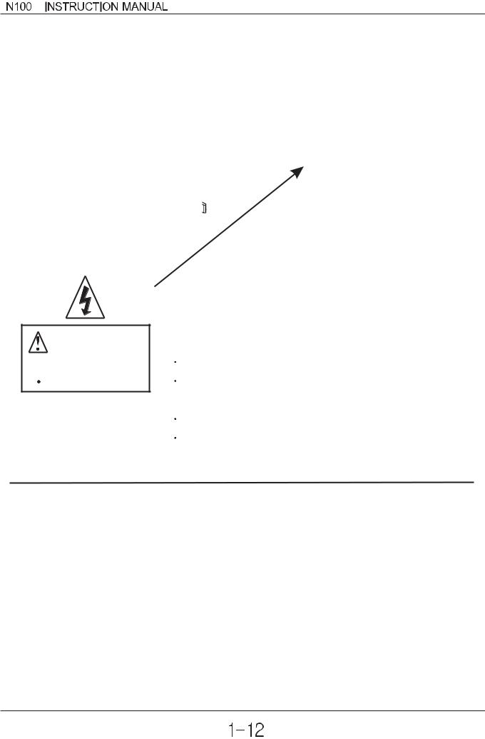
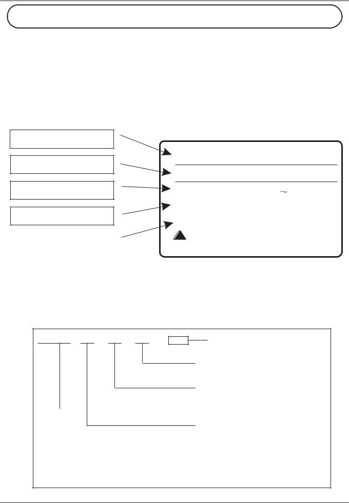
WARNING DISPLAY
WARNING
 DANGER
Risk of electric shock.
Before opening the cover, wait at least 5 minutes until DC bus capacitors discharge. Ensure proper earth connection.
Refer to the user's manual before installation and operation.
A warning label is displayed on the terminal cover of the inverter,
as shown in the figure.
Follow these instructions when handling the inverter.
plus


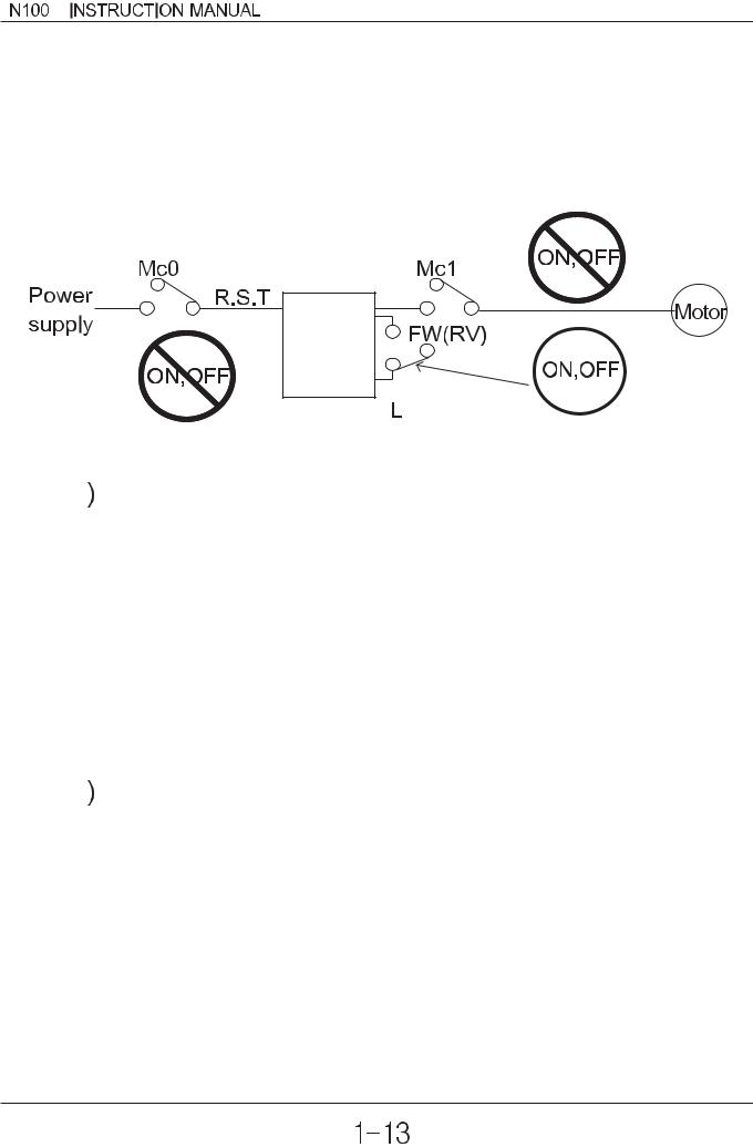
 Do not Run/Stop operation by switching on/off electromagnetic contactors (Mc0, Mc1) on the primary or secondary sides of the inverter.
Operate the inverter by Run/Stop commanding [FW/RV].
Inverter

 Motor Terminal Surge Voltage Suppression Filter (for the 400V class)
In a system using an inverter with the voltage control PWM system, a voltage surge caused by the cable constants such as the cable length (especially when the distance between the motor and inverter is 10m or more) and cabling method may occur at the motor terminals. A dedicated filter of the 400V class for suppressing this voltage surge is available. Be sure to install a filter in this situation.

 Input power disconnection
This inverter is not able to protect input power disconnection. Be careful to connect the wires.
plus


 In the cases below involving a general-purpose inverter, a large peak current flows on the power supply side, sometimes destroying the converter module.
 The unbalance factor of the power supply is 3% or higher.
 The power supply capacity is at least 10 times greater than the inverter capacity(and the power supply capacity, 500kVA or more).
 Abrupt power supply changes are expected.
some examples) Several inverters are interconnected with a short bus. An installed leading capacitor opens and closes.


 RC Value of the thermal Relay is 1.1 times greater than the motor rated current. Also, RC Value is adjustable to the wiring distance, but contacts us in this case.


 Do not connect and disconnect the power supply more than 1/5(number / minute)
There is the danger of inverter damage.


 When the EEPROM error E 08 occurs, be sure to confirm the setting values again.
N100plus INSTRUCTION MANUAL
2. Receiving and checking
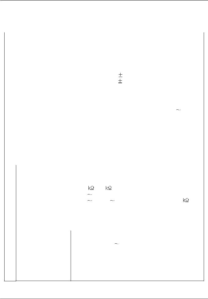
Inverter Specifications Label
Before installing and wiring, check the following
(1)Check the unit for physical damage that may have occurred during shipping
(2)Verify that the package contains one inverter and one manual
after packing the N100plus inverter.
(3) Verify that the specifications on the labels match your purchase order
Inverter model number
Motor capacity for this model
Model : N100plus-015LF
Power : 1.5kW/2HP
Power Input Rating: frequency, voltage, phase
Output Rating: Frequency, voltage, phase current
|
Input : 50Hz/60Hz |
200 230V 3Ph |
|
|
Output : 0.5-400Hz 200 |
230V 3ph 7.0A |
|
|
MFG NO : |
|
|
|
HYUNDAI |
Customer Service Center |
|
Manufacturing codes: |
|||
052)230-8445/6 |
|||
Lot number, date, etc. |
HEAVY INDUSTRIES CO., LTD. |
||
|
|||
|
|
|
If any part of N100plus is missing or damaged, call for service immediately
Model Number convention
The model number for a specific inverter contains useful information about its operating characteristics. Refer to the model number legend below:
N100plus - 015 H F
Series name
Directive type :
E: CE directive, blank : UL directive
Configuration type F:operator pannel equipped
Input voltage:
S: single phase 200V class
L: three-phase only 200V class H: three-phase 400V class
Maximum applicable motor capacity (4P, kW)
004: 0.4kW 007: 0.75kW 015: 1.5kW 022: 2.2kW 037: 3.7kW
2-1

N100plus INSTRUCTION MANUAL
3. N100plus Inverter Standard Specifiations.
Model-specific tables for 200V and 400V class inverters
The following two tables are specific to N100plus inverters for the 200V and 400V class model groups. The table on page 3-3 gives the general specifications that apply to both voltage class groups. Footnotes for all specifications tables are on the next page.
Item |
|
|
200V Class Specifications |
|
|
|||||
|
|
|
|
|
|
|
|
|
|
|
plus |
N100plus |
N100plus |
N100plus |
N100plus |
N100plus |
N100plus |
N100plus |
N100plus |
||
Model N100 series |
-004SF |
-007SF |
-015SF |
-004LF |
-007LF |
-015LF |
-022LF |
-037LF |
||
|
|
|||||||||
|
|
|
|
|
|
|
|
|
|
|
|
kW |
0.4 |
0.75 |
1.5 |
0.4 |
0.75 |
1.5 |
2.2 |
3.7 |
|
Applicable motor size *2 |
|
|
|
|
|
|
|
|
|
|
HP |
1/2 |
1 |
2 |
1/2 |
1 |
2 |
3 |
5 |
||
|
||||||||||
|
|
|
|
|
|
|
|
|
|
|
Rated capacity(200V)kVA |
1.1 |
1.9 |
3.0 |
1.1 |
1.9 |
3.0 |
4.2 |
6.1 |
||
|
|
|
|
|
|
|
|
|
|
|
|
|
Single-phase |
|
There-phase (3-wires) |
|
|||||
Rated input voltage |
200 to 230V |
10%, |
|
200 to 230V |
10%, |
|
||||
|
|
50/60 Hz |
5% |
|
50/60 Hz |
5% |
|
|||
|
|
|
|
|
|
|
|
|
|
|
Rated output voltage *3 |
3-phase 200 to 230V (corresponding to input voltage) |
|||||||||
|
|
|
|
|
|
|
|
|
|
|
Rated output current(A) |
3.0 |
5.0 |
7.0 |
3.0 |
5.0 |
7.0 |
11.0 |
17.0 |
||
|
|
|
|
|
|
|
|
|
|
|
Starting torque |
|
|
|
|
|
|
|
|
||
(with sensorless vector |
|
|
200% or more |
|
|
|
||||
control selected) |
|
|
|
|
|
|
|
|
||
|
|
|
|
|
|
|
|
|
|
|
Dynamic braking |
without resistor, |
|
|
approximately |
|
|
approximately |
||
from 50/60Hz |
|
|
100% |
|
|
20 |
40% |
||
approx. % torque, |
|
|
|
|
|
|
|
|
|
|
|
|
approximately |
|
|
approximately |
|||
short time stop *5 with resistor |
|
|
|
|
|||||
|
|
150% |
|
|
100% |
||||
|
|
|
|
|
|
||||
|
|
|
|
|
|
|
|
|
|
DC braking |
Variable operating frequency, time and braking force |
||||||||
|
|
|
|
|
|
|
|
|
|
Weight (kg) |
|
1.2 |
1.2 |
1.5 |
1.2 |
1.2 |
1.5 |
1.5 |
2.0 |
|
|
|
|
|
|
|
|
|
|
3-1

N100plus INSTRUCTION MANUAL
Item |
|
|
400V Class Specifications |
|
||||||
|
|
|
|
|
|
|
|
|
|
|
|
|
|
|
plus |
plus |
|
|
plus |
plus |
plus |
|
plus |
|
N100 |
N100 |
|
N100 |
N100 |
N100 |
||
Model N100 series |
-004HF |
-007HF |
|
-015HF |
-022HF |
-037HF |
||||
|
|
|
|
|
||||||
|
|
|
|
|
|
|
|
|
|
|
Applicable motor |
|
kW |
0.4 |
0.75 |
|
1.5 |
2.2 |
3.7 |
||
|
|
|
|
|
|
|
|
|
||
size *2 |
|
|
HP |
1/2 |
1 |
|
2 |
|
3 |
5 |
|
|
|
|
|
||||||
|
|
|
|
|
|
|
|
|
||
Rated capacity(200V)kVA |
1.1 |
1.9 |
|
3.0 |
4.2 |
6.1 |
||||
|
|
|
|
|
|
|
|
|
||
Rated input voltage |
|
3-phase : 380 to 460V |
10%, |
|
||||||
|
|
50/60Hz |
5% |
|
|
|||||
|
|
|
|
|
|
|
||||
|
|
|
|
|
|
|
|
|||
Rated output voltage *3 |
3-phase 380 to 460V (corresponding to input voltage) |
|||||||||
|
|
|
|
|
|
|
|
|
||
Rated output current(A) |
1.8 |
3.4 |
|
4.8 |
7.2 |
9.2 |
||||
|
|
|
|
|
|
|
|
|
|
|
Starting torque |
|
|
|
|
|
|
|
|
||
(with sensorless vector |
|
200% or more |
|
|
|
|||||
control selected) |
|
|
|
|
|
|
|
|
||
|
|
|
|
|
|
|
|
|
|
|
Dynamic braking |
without resistor, |
approximately |
|
|
approximately |
|||||
approx. % torque, |
from 50/60Hz |
|
100% |
|
|
|
20 |
40% |
||
|
|
|
|
|
|
|
|
|
|
|
short time stop *5 |
with resistor |
approximately |
|
|
approximately |
|||||
|
100% |
|
|
|
100% |
|||||
|
|
|
|
|
|
|
|
|||
DC braking |
|
Variable operating frequency, time and braking force |
||||||||
|
|
|
|
|
|
|
|
|
|
|
Weight(kg) |
|
1.2 |
1.5 |
|
1.5 |
2.0 |
2.0 |
|||
|
|
|
|
|
|
|
|
|
|
|
3-2
N100plus INSTRUCTION MANUAL
General Specifications
The following table applies to all N100plus inverters.
|
|
Item |
|
|
General Specifications |
|
||
|
|
|
|
|
||||
Protective housing *1 |
Enclosed type(IP20) |
|||||||
|
|
|
|
|
||||
Control method |
Space vector PWM control |
|||||||
|
|
|
|
|
|
|||
Output frequency range *4 |
0.01 to 400Hz |
|
|
|
||||
|
|
|
|
|
|
|||
Frequency accuracy |
Digital command : 0.01% of the maximum frequency |
|||||||
Analog command : 0.1% of the maximum frequency |
||||||||
|
|
|
||||||
|
|
|
|
|
|
|||
|
|
|
Digital : 0.01Hz(100Hz and less), 0.1Hz |
|||||
Frequency setting |
|
(100Hz or more) |
||||||
resolution |
|
Analog : Max. Setting frequency / 500(DC 5V input), |
||||||
|
|
|
max. setting frequency / 1000(DC 10V, 4 20mA) |
|||||
|
|
|
|
|
||||
|
|
|
Any base freguency setting possible between 0Hz |
|||||
Volt./ Freq. Characteristic |
and 400Hz. |
|
|
|
||||
|
|
|
V/F control (constant torque, reduced torque). |
|||||
|
|
|
|
|
||||
Overload current rating |
150%, 60 seconds |
|||||||
|
|
|
|
|
||||
Acceleration/deceleration |
0.1 to 3000sec., (linear accel. / decel. s-curve, |
|||||||
time |
|
u-curve), second accel. / decel. setting available |
||||||
|
|
|
|
|
|
|||
|
|
Operator panel |
Up and Down keys / Value settings |
|||||
|
|
|
|
|
||||
|
Freq- |
Potentiometer |
Analog setting via potentiometer. |
|||||
|
setting |
|
|
|
|
|
|
|
|
External signal |
1W, 1 |
to 2 |
variable resistor |
||||
|
|
|||||||
|
|
|
DC 0 |
5V |
|
|
|
|
|
|
|
DC 0 |
10V, 4 |
20mA(Input Impedonce 10 ) |
|||
signal |
|
|
|
|
||||
FWD/ |
Operator panel |
Run/Stop(Forward/Reverse run change by command) |
||||||
REV |
|
|
|
|
|
|
||
|
Forward run/stop, Reverse run/stop set by terminal |
|||||||
Run |
|
|||||||
Input |
External signal |
|||||||
assignment (NC/NO) |
||||||||
|
||||||||
|
|
|
|
|
|
|
||
|
|
|
|
|
|
|
||
Intelligent input terminal
N100plus INSTRUCTION MANUAL
|
Item |
General Specifications |
|
|
|
RUN(run status signal), FA1 (frequency arrival |
|
|
Intelligent output |
signal), FA2 (setting Frequency arrival signal), |
|
signal |
terminal |
OL(overload advance notice signal), OD(PID error |
|
|
deviation signal), AL(alarm signal) |
||
|
|
||
|
|
|
|
Output |
|
Analog meter (DC0 10V full scale, Max. 1mA) |
|
Frequency monitor |
Analog output frequency, Analog output current and |
||
|
|||
|
|
Analog output voltage signals selectable. |
|
|
|
OFF for inverter alarm(normally closed contact |
|
|
Alarm output contact output) (Transition to ON for alarm)/Intelligent |
||
|
|
output Terminal |
|
|
|
|
|
|
AVR function, curved accel./decel. profile, upper and |
|
|
lower limiters, 16-stage speed profile, fine adjustment |
|
|
of start frequency, carrier frequency change (0.5 to |
|
|
16Khz), frequency jump, gain and bias setting, process |
|
Other functions |
jogging, electronic thermal level adjustment, retry |
|
function, trip history monitor, 2nd setting selection, |
||
|
||
|
auto tuning, V/f characteristic selection, automatic |
|
|
torque boost, frequency coversion display, USP |
|
|
function |
|
|
Over-current, over-voltage, under-voltage, overload, |
|
|
extreme high/low temperature, ground fault |
|
Protective function |
detection, internal communication error, external |
|
|
trip, EEPROM error, USP error, instantaneous |
|
|
power failure, output short-circuit detection. |
-10 to 50 (If ambient temperature exceed 40
 , Ambient temperature reduce the carrier frequency to 2.1kHz or less and
the rated current to 80% or less)
Operating Environment |
Storage temperature |
-20 |
60 |
(short-term temperature during |
|
transport) |
|
||
|
|
|
||
|
Ambient humidity |
90% RH or less (no condensing) |
||
|
|
|
|
|
|
|
2 |
(0.6G), 10 to 55Hz(conforms to the test |
|
|
Vibration |
5.9m/s |
||
|
method specified in JIS C0911) |
|||
|
|
|||
|
|
|
||
|
Location |
Altitude 1,000m or less, indoors(no corrosive gasses |
||
|
or dust) |
|
|
|
|
|
|
|
|
|
|
Remote operator unit, cable for operator, braking |
||
|
Options |
unit, braking |
resistor, AC reactor, DC reactor, |
|
|
noise filter. |
|
||
|
|
|
||
|
|
|
|
|
3-4

N100plus INSTRUCTION MANUAL
Footnotes for the preceding tables :
1.The protection method conforms to JEM 1030.
2.The applicable motor refers to HYUNDAI standard 3-phase motor (4-pole). To use other motors, care must be taken to prevent the rated motor current(50/60Hz) from exceeding the rated output current of the inverter.
3.The output voltage decreases as the main supply voltage decreases (except for use of the AVR function). In any case, the output voltage cannot exceed the input power supply voltage.
4.To operate the motor beyond 50/60Hz, consult the motor mamanufacturer about the maximum allowable rotation speed.
5.The braking torque via capacitive feedback is the average decelection torque at the shortest deceleration (stopping from 50/60Hz as indicated). It is not continuous regenerative braking torque. And, the average deceleration torque varies with motor loss. This value decreases when operating beyond 50 Hz. If a large regenerative torque is required, the optional regenerative braking resistor should be used.
6.Control method setting A31 to 2 (sensorless vector control) Selected, set carrier frequency setting b11 more than 2.1kHz.
3-5
N100plus INSTRUCTION MANUAL
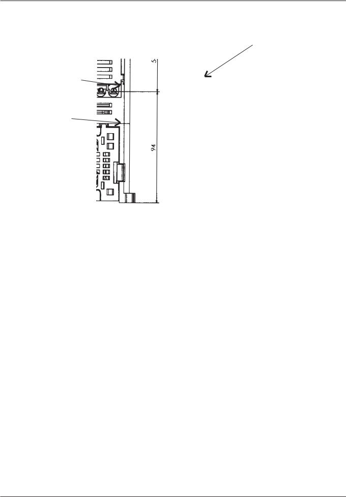
4. External Dimension Diagrams and Identifying the parts
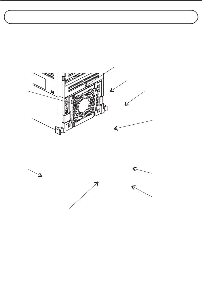
Main Physical Features
Display part
Front cover
Control key
Terminal cover(Note)
Communication port
 Main circuit terminal
Mounting hole
Cooling fan
Fan cover
Ground Terminal
Removing terminal cover :
Use a hand and press on the terminal cover surface to remove it. Control wiring can be possible by removing terminal cover.
Note) Do not press excessive pressure. Otherwise, the cover may be damaged.
4-1
N100plus INSTRUCTION MANUAL
Front cover
Bolt
Wiring cover
Use a screwdriver to loosen the Bolt on the front cover.
Notice the wiring cover that lifts out to allow full access to the terminals for wiring.
After removing terminal cover, locate the recessed retention screw on the left side main front panel.
Use a small screwdriver to loosen the screw, swing the door around to the left to reveal the internal components of the drive.
4-2

N100plus INSTRUCTION MANUAL
Inverter Dimensions for Mounting
The N100plus Series inverters have a digital operator as a standard and contains all the elements for monitoring and setting parameters.
The optional remote operator may be available for remote operation. Locate the applicable drawing on the following pages for your inverter. Dimensions are given in millimeters (inches) format.
004SF/LF
007SF/LF
004HF
015SF/LF
022LF
007HF
015HF
4-3
N100plus INSTRUCTION MANUAL
037LF
022HF
037HF
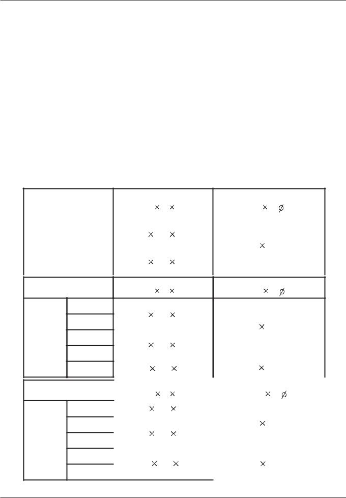
 Dimension table by the capacity
TYPE |
External dimension(mm) Installation |
dimension(mm) |
||
(W H D) |
(W |
H. ) |
||
|
||||
|
004SF |
115 |
130 |
135 |
|
|
|
|
1-phase |
|
|
|
|
||||
007SF |
105 |
120,M4 |
||||||
|
|
|
||||||
200V |
|
|
|
|||||
|
|
|
|
|
|
|
||
class |
015SF |
115 |
130 |
155 |
|
|
|
|
|
|
|
|
|
|
|
|
|
TYPE
004LF
3-phase 007LF
200V 015LF
class
022LF
037LF
TYPE
004HF
3-phase 007HF
400V 015HF
class
022HF
037HF
External dimension(mm) Installation |
dimension(mm) |
|
(W H D) |
(W |
H. ) |
115 |
130 |
135 |
|
|
||
|
|
|
|
105 |
120,M4 |
|
115 |
130 |
155 |
||||
|
|
|||||
|
|
|
|
|
|
|
150 |
130 |
155 |
140 |
120,M4 |
||
|
|
|
|
|||
|
|
|
|
|||
|
External dimension(mm) |
Installation |
dimension(mm) |
|||
|
(W |
H |
D) |
(W |
H. ) |
|
|
|
|
|
|
|
|
115 |
130 |
135 |
|
|
||
|
|
|
|
105 |
120,M4 |
|
|
|
|
|
|||
|
115 |
130 |
155 |
|
|
|
|
|
|||||
|
|
|
||||
|
|
|
|
|
|
|
150 |
130 |
155 |
140 |
120,M4 |
||
|
|
|
|
|
|
|
4-4
N100plus INSTRUCTION MANUAL
5. Installation
Choosing a Mounting Location
 CAUTION
Be sure to install the unit on flame-resistant material such as a steel plate. Otherwise, there is the danger of fire.
Be sure not to place any flammable materials near the inverter. Otherwise, there is the danger of fire.
Be sure not to let the foreign matter enter vent openings in the inverter housing, such as wire clippings, spatter from welding, metal shaving, dust, etc.
Otherwise, there is the danger of fire.
Be sure to install the inverter in a place which can bear the weight according to the specifications in the text
Otherwise, it may fall and cause injury to personnel.
 CAUTION
Be sure to install the unit on a perpendicular wall which is not subject to vibration.
Otherwise, it may fall and cause injury to personnel.
Be sure not to install or operate an inverter which is damaged or has missing parts.
Otherwise, there is the danger of fire.
Be sure to install the inverter in a well-ventilated room which does not have direct exposure to sunlight, a tendency for high temperature, high humidity or dew condensation, high levels of dust, corrosive gas, explosive gas, inflammable gas, grinding fluid mist, salt damage, etc.
Otherwise, there is the danger of fire.
5-1
N100plus INSTRUCTION MANUAL
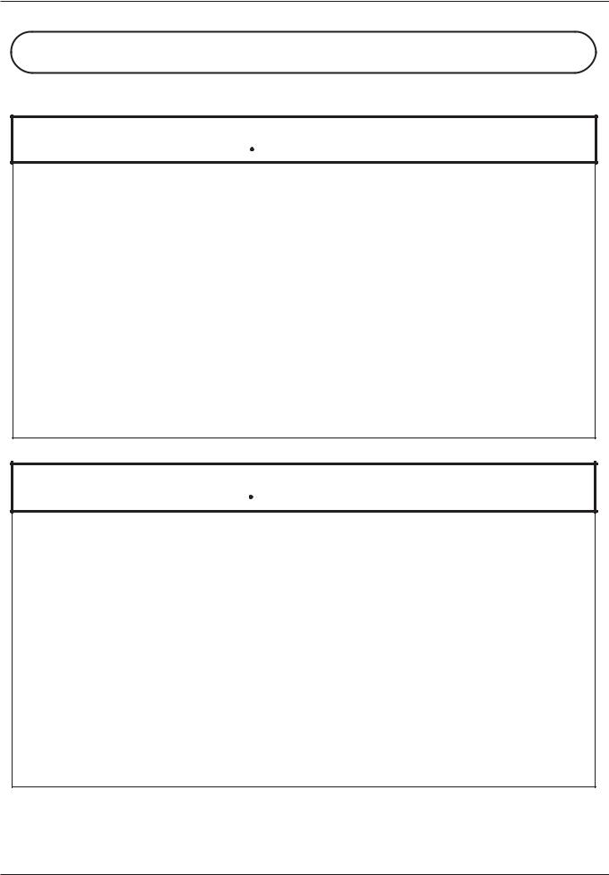
To summarize the cautions messages-You will need to find a solid, nonflammable, vertical surface that is a relaticely clean and any envirnment. In order to ensure enough room for air circulation around the inverter to aid in cooling, maintain the specified clearance around the inverter specified in the diagram.
|
10cm |
Air flow |
|
|
minimum |
||
|
|
||
8cm |
12cm |
Wall |
|
minimum |
minimum |
||
|
10cm minimum
 CAUTION
Solid, nonflammable, vertical surface
Before proceeding to the wiring section, it's good time to temporarily
cover the inverter's ventilation openings. It will prevent harmful debris such as wire clippings and metal shavings from entering the inverter during installation
 CAUTION
The ambient temperature must be in the range of-10 to 40 . If the range will be up to 50
 , you will need to set the carrier frequency to 2kHz or less and derate the output current to 80% or less.
5-2
N100plus INSTRUCTION MANUAL
6.Wiring
 DANGER
Be sure to ground the unit.
Otherwise, there is a danger of electric shock and/or fire.
Wiring work shall be carried out only by qualified personnel. Otherwise, there is a danger of electric shock and/or fire.
Implement wiring after checking that the power supply is off. You may incur electric shock and/or fire.
Do not connect wiring to an inverter or operate an inverter that is not mounted according the instructions given in this manual.
Otherwise, there is a danger of electric shock and/or injury to personnel.
 CAUTION
Be sure to that input voltage matches the inverter specifications. Otherwise, there is a danger of electric fire and/or injury to personnel.
Be sure not to connect an AC power supply to the output terminals. Otherwise, there is a danger of electric fire and/or injury to personnel.
Be sure not to connect a resistor to the DC-link terminal(P, PB). Otherwise, there is a danger of fire
Remarks for using earth leakage circuit breakers in the main supply. Otherwise, there is a danger of fire.
For motor leads, earth leakage breakers and electromagnetic contactors, be sure to size these components properly.
Otherwise, there is a danger of fire.
Do not RUN/STOP operation by switching ON/OFF electromagnetic contactors on the primary or secondary sides of the inverter.
Otherwise, there is a danger of fire.
Fasten the screws with the specified fastening torque.
Otherwise, there is a danger of fire.
6-1
N100plus INSTRUCTION MANUAL
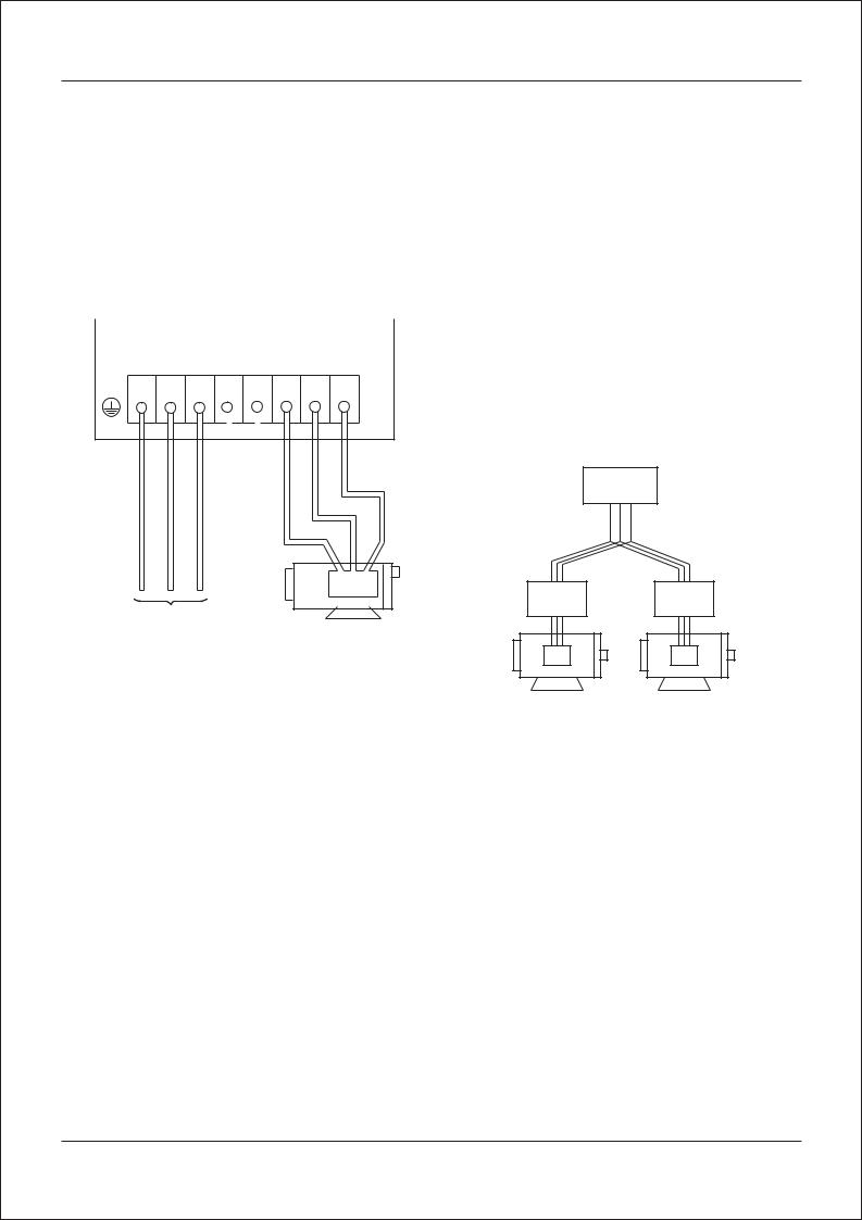
6.1 Wiring the main circuit
You will connect main circuit terminal wiring to the input of the inverter. For wiring, open the front cover and wiring cover.
Ex)N100plus-004LF
R S T P RB U V W
Inverter
Thermal |
Thermal |
Relay |
Relay |
Power supply
Motor
Motor Motor
Always connect the power input terminals R, S, and T to the power supply. Be sure to install thermal relay individually when one inverter operates several motors.
Never connect P, RB, to R, S, T, or U, V, W. Otherwise, there is the danger of equipment damage.
6-2
 Loading...