


Hydraulic System
R210LC-9
- 1 - |
Hyundai Training Center |

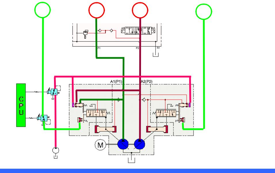
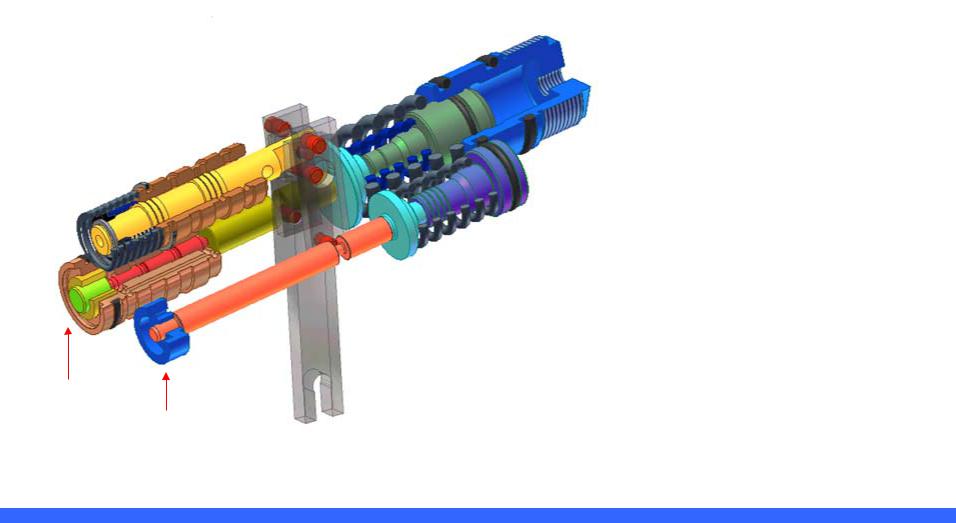
Pump Assembly
Pi1=Neg. Control
Pm1=Flow Cut Off
Regulator 1
Regulator 2
 Pi2=Neg. Control
Pm2=Flow Cut Off
EPPR Pressure
EPPR Valve |
35 bar |
P1 Front |
|
P2 Rear |
|
Pilot Pump |
|
|
|
|
|
- 2 - |
Hyundai Training Center |
1. Main Pump |
R210LC-9 |
|
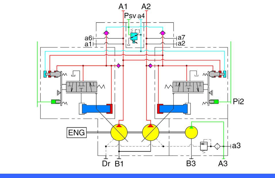
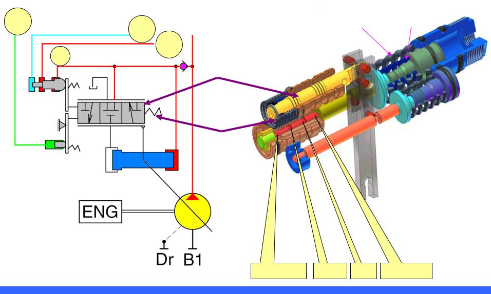
1-1. Hydraulic circuit
Pi1 |
Pi2 |
Horsepower
Control Function
Flow Control
Function
- 3 - |
Hyundai Training Center |
R210LC-9
Pi1 |
P1 |
P2 |
Pi2 |
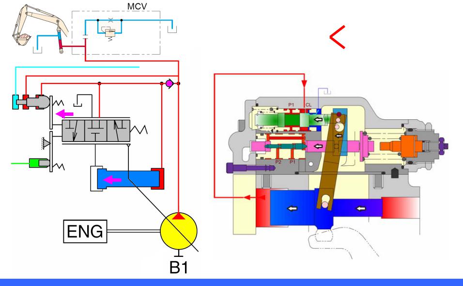
1)P1,P2 : Main Pump
2)Pi1,Pi2 : Positive control
3)Psv : EPPR V/V
|
|
P1 |
P2 |
- 4 - |
Hyundai Training Center |

R210LC-9
Pi pressure-1
Low
High pressure
No work
Low
- 5 - |
Hyundai Training Center |
R210LC-9
Pi pressure-2
High
Low pressure
Work
High
- 6 - |
Hyundai Training Center |
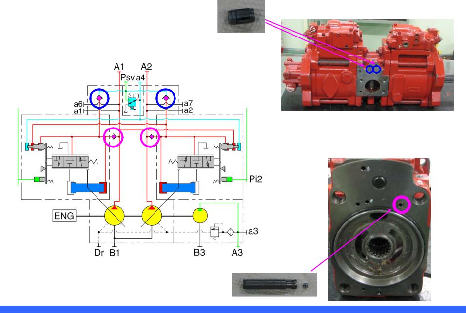
1-2. Check Valve |
R210LC-9 |
Pi1 |
Pi2 |
- 7 - |
Hyundai Training Center |
2. Pump Regulator |
R210LC-9 |
2-1. Function-1
1) Horsepower control function (negative system)
Power Shift Control
Pump self pressure and the other Pump Pressure
2) Flow Control Function
(Posi-Nega Flow Control)
(Pi1,Pi2) Control
Qmax cut-off EPPR Control
Horsepower
control part Flow Control Part
- 8 - |
Hyundai Training Center |
2-2. Function-2 |
R210LC-9 |
1) Horsepower Control Function |
2) Flow Control Function |
(Negative Control) |
(Posi-Nega Flow Control) |
- P1, P2, Pf Control |
- Pi pressure and Max. Flow cut EPPR. Control |
|
- 9 - |
Hyundai Training Center |
2-3. Regulator Circuit and Structure
Pi
Pf
P2
P1
R210LC-9
Outer spring |
Inner spring |
Pf (EPPR) |
P2 |
P1 |
Drain |
- 10 - |
Hyundai Training Center |
2-4. Horsepower Control (Negative Flow Control) |
R210LC-9 |
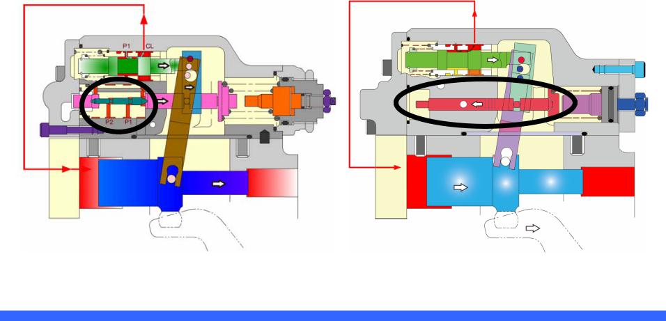
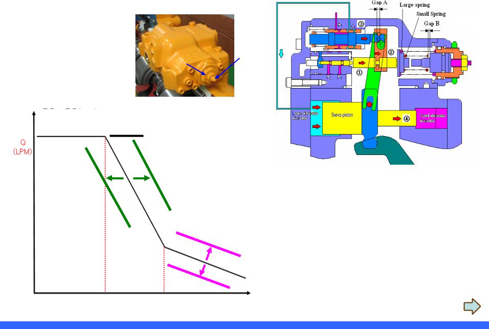
2-4-1. Overload protecting function
Pf
When P1,P2 pressure rise up, compensation piston begins to push the rod balancing with spring force. When the hydraulic pressure exceeds the spring force, then hydraulic oil will be supplied to large chamber of servo piston and the pump discharge rate will be reduced.
Cylinder Pressure |
Spring Force |
(Discharge rate Decrease)
- 11 - |
Hyundai Training Center |
|
Q |
|
rpm |
? |
|
|
|
HP P X Q |
|
|
P |
- 12 - |
Hyundai Training Center |
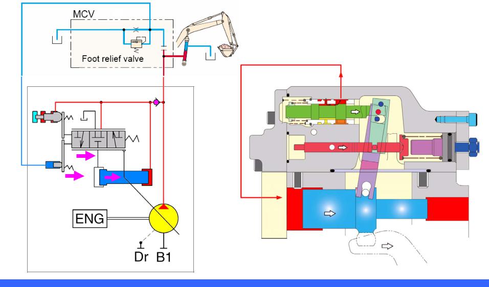
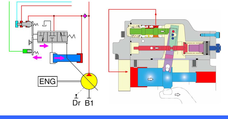
2-4-2. Recovery of flow |
R210LC-9 |
When P1,P2 pressure decrease, the spring force pushing the compensation piston rod exceeds the hydraulic pressure and shifts the compensation piston. Then large chamber of servo piston is connected to tank, that makes pump discharge rate increase.
Cylinder Pressure |
Spring Force |
(Discharge rate Increase)
Pf
- 13 - |
Hyundai Training Center |
2-4-3. Adjustment of power
Screw clockwise (Flow ↑)
Screw
Counterclockwise
(Flow ↓)
Screw clockwise (Flow ↑)
Screw counter clockwise (Flow ↓)
Pressure
Adjustment of 1st power
-Release lock nut of 36mm
-Adjust screw of 24mm
Adjustment of 2nd power
-Release lock nut of 13mm
-Adjust rectangle screw
- 14 - |
Hyundai Training Center |
2-5. Flow Control Function (Negative Control Function) |
R210LC-7A |
2-5-1. Flow decrease
- RCV Lever neutral and fine control
Pi increase
- 15 - |
Hyundai Training Center |

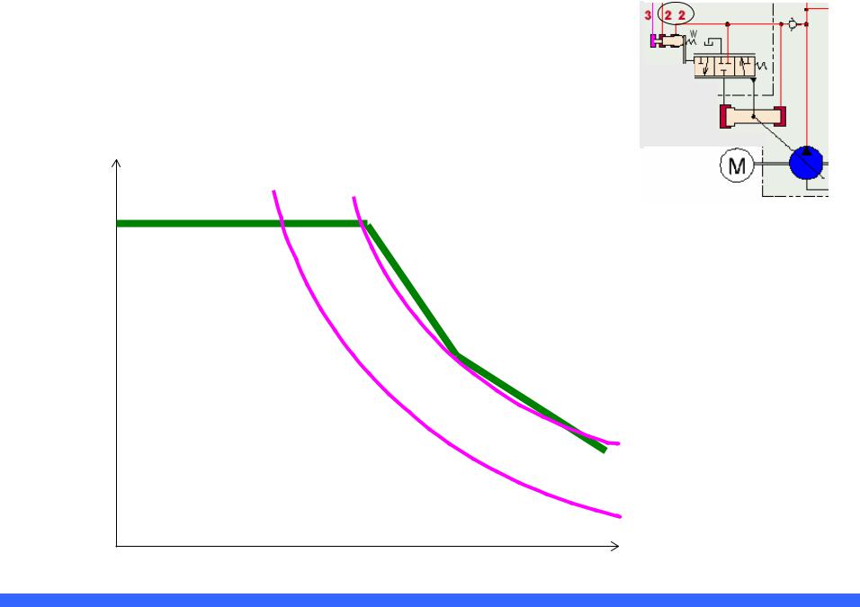
2-5-2. P-Q Graph (Relation between Pi and Flow) |
R210LC-7A |
|||||
|
||||||
|
|
|
|
|
|
|
|
|
|
|
|
|
|
|
|
|
|
|
|
|
|
|
|
|
|
|
|
Pilot flow control Screw
Screw : Counter clockwise (Flow ↓)
Screw : Clockwise (Flow ↑)
Pi1,Pi2
Flow control by controlling negative pressure (Pi1,Pi2).
- 16 - |
Hyundai Training Center |
2-6. Flow Control Function (Posi-Nega Control Function) |
R210LC-9 |
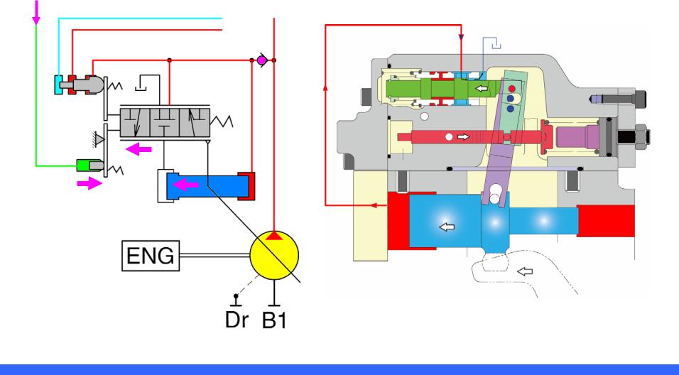
2-6-1. Flow Increase
- Operating Attachment
Pi increase
Pf
P2
- 17 - |
Hyundai Training Center |
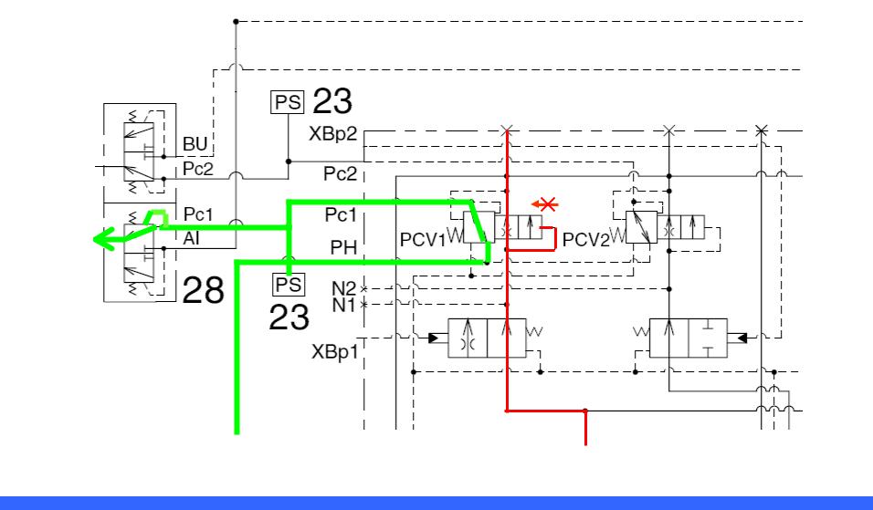
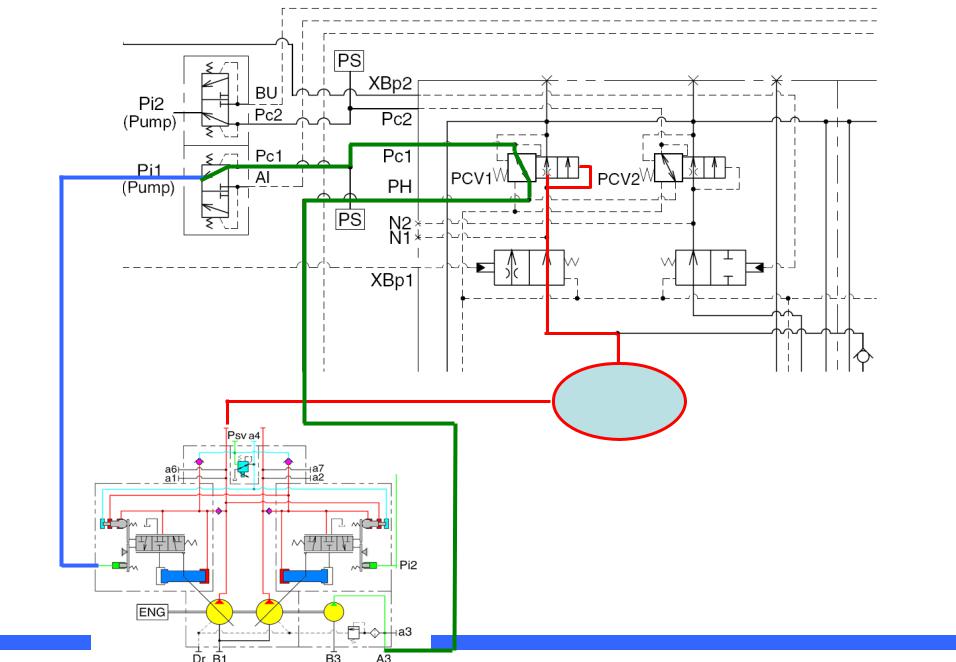
2-6-2. Flow Control when operating RCV lever (Relief) |
R210LC-9 |
When any of main spools is changed over, the bypass circuit is cut off. The posi-nega conversion valve spool is not shifted. At this time, “PH” pressure discharged from “P3” pump will flow to regulator “Pi1” passing through posi-nega conversion valve and shuttle valve. That will make pump discharge rate increase.
Pi2
(Pump)
Pi1
(Pump)
PH |
Dr1 |
CENTER BYPASS |
- 18 - |
Hyundai Training Center |
2-6-3. Posi-Nega Conversion Valve when RCV Lever is positioned at full position (Relief) |
R210LC-9 |
MCV Center bypass
Pi1
(Pump)
Low pressure can’t shift the Spool.
- 19 - |
Hyundai Training Center |
2-6-4. Flow decrease |
R210LC-9 |
- RCV Lever neutral and fine control
Pi decrease
Pf
P2
- 20 - |
Hyundai Training Center |
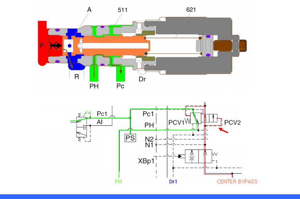
2-6-5. Flow Control when RCV lever is in neutral position |
R210LC-9 |
When hydraulic oil passing through the center bypass line increases, the posi-nega conversion valve spool moves to the left side. At this time, oil discharged from P3 pump will be blocked and Pc1 will be connected to the drain line, “Dr1”, it makes Pp11 line pressure lower and controls pump discharge flow rate to its minimum value.
PH |
Dr1 |
CENTER BYPASS |
- 21 - |
Hyundai Training Center |
 Loading...