


H-LCD700
PORTABLE LCD TV |
ПЕРЕНОСНОЙ ЖК-ТЕЛЕВИЗОР |
|
|
Instruction manual |
Руководство пльзователя |

Instruction manual
Dear customer!
Thank you for purchasing our product. For safety, it is strongly recommended to read this manual carefully before connecting, operating and/or adjusting the product and keep the manual for reference in the future.
Important safeguards
•Never attempt your own maintenance. If something appears strange, please turn the TV off and consult your TV dealer. The TV is composed of many delicate electronic components that can be damaged or broken if you open the TV or attempt to modify it.
•Do not expose the TV to high humidity, dust, steam, oil, smoke, direct sunlight etc.
•Do not use thinners or other chemical reagent. Wipe the TV off with a soft cloth if it gets dirty.
•Do not leave the TV in excessively hot or cold places. Permissible storage temperatures are within the range of –20°C to +60°C. Permissible operation temperatures are within the range of 0°С to +40°С.
•Only use specified adaptors and power sources.
•Turn power OFF when not in use and unplug the adaptor.
•Avoid dropping and strong impact.
•For your safety, the driver should not watch TV or operate the controls while driving.
•Please note that watching and operating the TV while driving are prohibited by law in some countries.
• That don’t mean the TV is broken with some light or dark color dots on the LCD, it’s a popular condition with the TFT-LCD technology.
Earphone operation precautions
•Please don’t tune your headphone/ earphone to a too high volume; otherwise it may lead inconvenience and danger to yourself and other people.
•For open-designed earphone, to avoid influencing your periphery, please tune down the volume.
•In case of any tinnitus, please tune down the volume or stop using this machine.
•It is recommended by the aurists to never use the earphone continuously for a long time.
Accessories |
|
LCD TV |
A/V cable |
Antenna |
Installation bracket |
Earphone |
Car power adapter |
Remote controller |
Instruction manual |
Stand |
Warranty card |
Power AC/DC |
Consumer |
adapter |
information |
2
Instruction manual
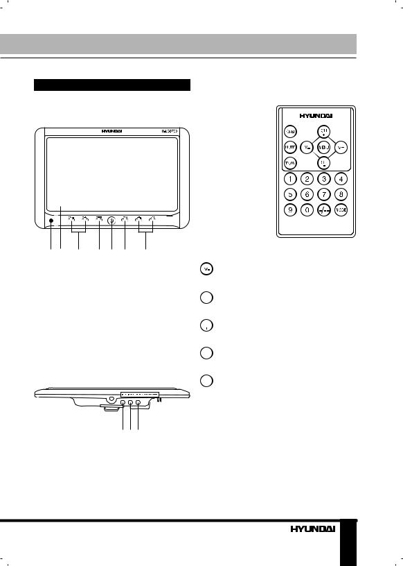
Control elements
Front panel
1 |
2 |
3 |
4 |
5 |
6 |
7 |
1.IR sensor
2.LCD display
3.VOL+/VOLbuttons
4.MENU button
5.POWER button
6.TV/AV button
7.CH+/CHbuttons
Back panel
1 2 3
1.AV in jack
2.Earphone jack
3.Power jack
Remote controller
 POWER button
Volume up button
 Mute button

 TV/AV button
 ~
~ Number buttons
 Channel+ button
 Menu button
 Volume down button
 Channelbutton

 Mode button
 Double digit button
• Please align the RC with the infrared-receiving window on TV set in operation.
•Never squeeze, drop, wet or disassembly the RC.
•Never press any button continuously and swiftly. Operation interval is at least 2 seconds.
3
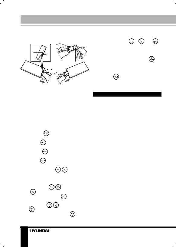
Battery installation |
|
|
the number of TV channel decreases. |
|||||||||
|
|
|
|
|
|
|
• |
Number buttons |
~ |
and |
||
|
|
|
|
|
|
|
button: When the channel is a one-digit |
|||||
|
|
|
|
|
|
|
figure, just press the corresponding |
|||||
|
|
|
|
|
|
|
number button. If the channel is a |
|||||
|
|
|
|
|
|
|
two-digit figure, you should press |
|||||
|
|
|
|
|
|
|
button first to show - - on the display |
|||||
|
|
|
|
|
|
|
screen before further pressing the |
|||||
|
|
|
|
|
|
|
corresponding number buttons. |
|
||||
|
|
|
|
|
|
|
• |
MODE/ |
button: Press this button |
|||
|
|
|
|
|
|
|
to select picture mode. |
|
|
|||
Insert the battery according to the |
Installation and connection |
|
||||||||||
picture above, observing the correct |
|
|||||||||||
polarities (+) and (-). Use one Cr2025 |
|
|
|
|
|
|||||||
size battery. If the RC fails to work |
|
Stand installation: |
|
|
||||||||
even operated near the unit, replace |
|
|
||||||||||
• Release the metal washer on the top |
||||||||||||
the battery. Do not use rechargeable |
||||||||||||
of the bracket but do not separate it from |
||||||||||||
batteries. Remove the battery when the |
||||||||||||
the bracket. |
|
|
|
|||||||||
RC will not be in use for a long time. |
|
|
|
|||||||||
• Insert the metal washer with the |
||||||||||||
|
|
|
|
|
|
|
||||||
Button functions |
|
|
|
bracket into a hollow at the back of the |
||||||||
|
|
|
unit and move the bracket up to a suitable |
|||||||||
• |
POWER/ |
button: Press this |
||||||||||
height. |
|
|
|
|||||||||
button to turn on or off the unit. |
|
|
|
|
||||||||
|
• Tighten the screw 1 up on the |
|||||||||||
• |
MENU/ |
button: Press this button |
||||||||||
bracket to fix the stand with the unit. |
||||||||||||
to display the on-screen menu. |
|
• Control the screen angle with the |
||||||||||
• |
AV/TV / |
button: Press this |
lateral screw. |
|
|
|
||||||
button to switch between video sources. |
• Screw the stand to the bracket. |
|||||||||||
• |
MUTE/ |
button: Press this button, |
Connection of the antenna: |
|||||||||
sound disappears; press it again or |
||||||||||||
press VOL+/VOLor |
/ |
buttons to |
Plug the antenna into the Antenna jack |
|||||||||
resume a normal sound. When sound is |
situated on the rear panel of the unit. |
|||||||||||
muted, a corresponding symbol appears |
|
|
|
|
|
|||||||
on the display. |
|
|
|
|
Connection of headphone: |
|||||||
• |
VOL-/VOL+ |
/ |
buttons: Press |
Connect the headphone to the |
||||||||
VOL-/ |
button, the volume of TV set |
headphone jack for private listening. |
||||||||||
decreases. Press VOL+/ |
button, the |
The speakers will not operate when |
||||||||||
volume of TV set increases. |
|
headphones are connected. |
|
|||||||||
• |
CH+/CH- / |
/ |
buttons: Press |
Connection to power source: |
||||||||
CH+/ |
button, the number of TV |
|
||||||||||
channel increases. Press CH-/ |
button, |
Connect one round end of attached |
||||||||||
4
Instruction manual
AC/DC adaptor or car adaptor to the power source input jack and the other end to the wall outlet at the suitable voltage. When in house, use the AC/DC adaptor; for car use, connect with the car adaptor (adaptors included should be only used). Press POWER/ button to turn on the unit.
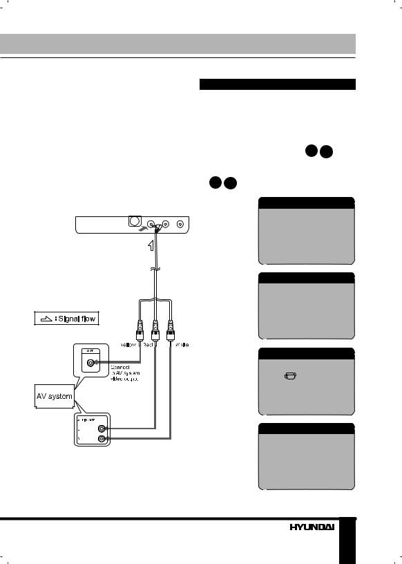
AV input connection
Connect the AV cable as showed in the picture below. After connection, switch the unit to the AV mode.
Menu operation
AV Mode
Press MENU or button to access setting menu for picture, audio, function, system and clock.
Press CH+/CHbuttons or  /
/
buttons to choose the parameter you need to adjust. Then press VOL+/VOLbuttons or  /
/ to adjust the parameter.
PICTURE
BRIGHT
CONTRAST
COLOR
AUDIO
VOLUME
FUNCTION
ZOOM
LANGUAGE
SIGNAL
SYSTEM
 This model has no memory card slot. The SD card hole is not functional and is shut with a rubber cover.
S-ROLOC S-SYS SWAP COPY
5
 Loading...