


 Loading...
Management and Configuration Guide for HP HP ProCurve M111 Client Bridge
ProCurve 5400zl Switches
HP ProCurve M111 Client Bridge
Installation and Getting Started Guide
Management and Configuration Guide

HP ProCurve M111 Client Bridge
Management and Configuration Guide

© Copyright 2010 Hewlett-Packard Development Company, L.P. The information contained herein is subject to change without notice.
This document contains proprietary information, which is protected by copyright. No part of this document may be photocopied, reproduced, or translated into another language without the prior written consent of Hewlett-Packard.
Publication Number
5998-0329 April 2010
Applicable Products
M111 Client Bridge (WW J9389A)
M111 Client Bridge (Japan J9523A)
Trademark Credits
Windows NT®, Windows®, and MS Windows® are US registered trademarks of Microsoft Corporation.
Disclaimer
HEWLETT-PACKARD COMPANY MAKES NO WARRANTY OF ANY KIND WITH REGARD TO THIS MATERIAL, INCLUDING, BUT NOT LIMITED TO, THE IMPLIED WARRANTIES OF MERCHANTABILITY AND FITNESS FOR A PARTICULAR PURPOSE. Hewlett-Packard shall not be liable for errors contained herein or for incidental or consequential damages in connection with the furnishing, performance, or use of this material.
The only warranties for HP products and services are set forth in the express warranty statements accompanying such products and services. Nothing herein should be construed as constituting an additional warranty. HP shall not be liable for technical or editorial errors or omissions contained herein.
Hewlett-Packard assumes no responsibility for the use or reliability of its software on equipment that is not furnished by Hewlett-Packard.
Warranty
See the Customer Support/Warranty booklet included with the product.
A copy of the specific warranty terms applicable to your Hewlett-Packard products and replacement parts can be obtained from your HP Sales and Service Office or authorized dealer.
Open Source Software Acknowledgement Statement
This software incorporates open source components that are governed by the GNU General Public License (GPL), version 2. In accordance with this license, HP ProCurve Networking will make available a complete, machine-readable copy of the source code components covered by the GNU GPL upon receipt of a written request. Send a request to:
Hewlett-Packard Company, L.P.
GNU GPL Source Code
Attn: ProCurve Networking Support
Roseville, CA 95747 USA
Safety
Before installing and operating this product, please read Safety information on page 1-5.
Hewlett-Packard Company
8000 Foothills Boulevard Roseville, California 95747 www.hp.com/go/procurve/

Contents
1 Introduction
About this guide ........................................................................................................... |
1-2 |
Products covered................................................................................................... |
1-2 |
Important terms..................................................................................................... |
1-2 |
Conventions ........................................................................................................... |
1-2 |
Warnings and cautions ................................................................................... |
1-2 |
Commands and program listings .................................................................. |
1-3 |
Introducing the M111 Client Bridge........................................................................... |
1-4 |
Key features............................................................................................................ |
1-4 |
Safety information........................................................................................................ |
1-5 |
Professional Installation Required ............................................................... |
1-5 |
Servicing........................................................................................................... |
1-5 |
HP ProCurve Networking support............................................................................. |
1-6 |
Before contacting support ............................................................................. |
1-6 |
Online documentation ................................................................................................. |
1-6 |
2 Getting started
Deploying the M111 ..................................................................................................... |
2-2 |
Scenario 1: Connecting wired devices to a wireless network ................................ |
2-2 |
Overview................................................................................................................. |
2-2 |
Configuration procedure ...................................................................................... |
2-3 |
A. Configure your computer.......................................................................... |
2-3 |
B. Connect to the M111 .................................................................................. |
2-4 |
C. Start the M111............................................................................................. |
2-4 |
D. Connect to the management tool and login............................................ |
2-4 |
E. Set the M111 IP address ............................................................................ |
2-5 |
F. Configure a station profile......................................................................... |
2-6 |
G. Connect the wired computers to the M111............................................. |
2-7 |

Contents
Scenario 2: Connecting a wired device using MAC address cloning |
.....................2-8 |
Overview................................................................................................................. |
2-8 |
Configuration procedure ...................................................................................... |
2-9 |
A. Configure your computer.......................................................................... |
2-9 |
B. Connect to the M111 .................................................................................. |
2-9 |
C. Start the M111............................................................................................. |
2-9 |
D. Connect to the management tool and login............................................ |
2-9 |
E. Set the M111 IP address ............................................................................ |
2-9 |
F. Configure a station profile......................................................................... |
2-9 |
G. Configure MAC cloning options............................................................... |
2-9 |
H. Connect the wired device to the M111.................................................. |
2-10 |
Scenario 3: Connecting a serial device to a wireless network ............................. |
2-11 |
Overview............................................................................................................... |
2-11 |
Configuration procedure .................................................................................... |
2-12 |
A. Configure your computer........................................................................ |
2-12 |
B. Connect to the M111 ................................................................................ |
2-12 |
C. Start the M111........................................................................................... |
2-12 |
D. Connect to the management tool and login.......................................... |
2-12 |
E. Set the M111 IP address .......................................................................... |
2-12 |
F. Configure a station profile....................................................................... |
2-12 |
G. Configure the serial connection............................................................. |
2-12 |
3 Working with the M111
Management tool.......................................................................................................... |
3-3 |
Starting the management tool.............................................................................. |
3-3 |
Customizing management tool settings.............................................................. |
3-4 |
Manager and Operator accounts................................................................... |
3-4 |
Security policies.............................................................................................. |
3-6 |
Security ............................................................................................................ |
3-6 |
Web server ....................................................................................................... |
3-7 |
Auto-refresh..................................................................................................... |
3-7 |
IP address configuration ............................................................................................. |
3-7 |
To configure IP addressing................................................................................... |
3-8 |
Radio configuration ..................................................................................................... |
3-9 |
Wireless range ........................................................................................................ |
3-9 |
iv

|
Contents |
To configure the radio......................................................................................... |
3-10 |
Wireless mode ............................................................................................... |
3-10 |
Restrict channels to...................................................................................... |
3-10 |
Antenna selection ......................................................................................... |
3-11 |
Fast roaming threshold |
|
Fast roaming delta threshold ...................................................................... |
3-11 |
Fast roaming threshold count ..................................................................... |
3-12 |
Minimum SNR threshold.............................................................................. |
3-12 |
Scan channel delay ....................................................................................... |
3-12 |
Fast scan channel delay ............................................................................... |
3-12 |
Roaming persistence .................................................................................... |
3-12 |
Advanced wireless settings ................................................................................ |
3-13 |
RTS threshold................................................................................................ |
3-13 |
Transmit power control ...................................................................................... |
3-13 |
Using station profiles to establish a wireless link.................................................. |
3-13 |
To add or edit a station profile........................................................................... |
3-15 |
General ........................................................................................................... |
3-15 |
Wireless security ........................................................................................... |
3-16 |
Quality of service .......................................................................................... |
3-18 |
Viewing APs in the neighborhood ............................................................................ |
3-18 |
Field descriptions ......................................................................................... |
3-19 |
Configuring Quality of Service (QoS)...................................................................... |
3-19 |
QoS settings in a station profile......................................................................... |
3-20 |
Priority mechanisms..................................................................................... |
3-20 |
Upstream DiffServ tagging........................................................................... |
3-22 |
Creating IP QoS profiles ..................................................................................... |
3-22 |
To define an IP QoS profile ................................................................................ |
3-22 |
Settings........................................................................................................... |
3-23 |
Connecting serial devices ......................................................................................... |
3-23 |
Serial port connector .......................................................................................... |
3-24 |
To connect a serial device .................................................................................. |
3-24 |
DNS configuration...................................................................................................... |
3-27 |
Handling unsupported traffic ................................................................................... |
3-29 |
To forward unsupported traffic ......................................................................... |
3-29 |
IP forwarding ....................................................................................................... |
3-30 |
v

Contents
Cloning the address of a wired device..................................................................... |
3-30 |
Limitations ..................................................................................................... |
3-30 |
Enabling Ethernet MAC cloning ........................................................................ |
3-31 |
Wireless access to the M111 when MAC cloning is active ............................. |
3-31 |
Setting up management traffic interception.............................................. |
3-32 |
Using filters to restrict wireless traffic.................................................................... |
3-33 |
Assigning a management address ............................................................................ |
3-34 |
To assign a management address ...................................................................... |
3-34 |
SNMP ........................................................................................................................... |
3-35 |
Attributes ....................................................................................................... |
3-36 |
v1/v2c communities ...................................................................................... |
3-36 |
v3 users .......................................................................................................... |
3-36 |
Notification receivers................................................................................... |
3-37 |
Security .......................................................................................................... |
3-37 |
Managing certificates................................................................................................. |
3-37 |
802.1X certificates ............................................................................................... |
3-38 |
802.1X — Install TLS client certificate....................................................... |
3-38 |
802.1X — Manage TLS client certificates .................................................. |
3-39 |
802.1X — Trusted CA certificates............................................................... |
3-39 |
802.1X — Manage CA certificates............................................................... |
3-39 |
Certificate stores ................................................................................................. |
3-39 |
Trusted CA certificate store ........................................................................ |
3-40 |
Certificate and private key store................................................................. |
3-41 |
Certificate usage .................................................................................................. |
3-42 |
Changing the certificate assigned to a service.......................................... |
3-43 |
About certificate warnings .......................................................................... |
3-43 |
Configuration file management................................................................................ |
3-44 |
Manual configuration file management ............................................................ |
3-44 |
Backup configuration................................................................................... |
3-44 |
Reset configuration ...................................................................................... |
3-45 |
Restore configuration................................................................................... |
3-45 |
Scheduled operations.......................................................................................... |
3-45 |
Software updates........................................................................................................ |
3-46 |
Performing an immediate software update...................................................... |
3-47 |
Performing a scheduled update......................................................................... |
3-47 |
vi

|
Contents |
A Regulatory information |
|
Notice for U.S.A. .................................................................................................... |
4-2 |
Notice for Canada.................................................................................................. |
4-3 |
Notice for the European Community.................................................................. |
4-3 |
Disposal of Waste Equipment by Users in Private Household in the |
|
European Union .............................................................................................. |
4-5 |
Supported External Antennas.............................................................................. |
4-5 |
Notice for Brazil..................................................................................................... |
4-5 |
Notice for Japan..................................................................................................... |
4-6 |
Notice for Taiwan .................................................................................................. |
4-6 |
Notice for Korea .................................................................................................... |
4-6 |
B Resetting to factory defaults |
|
How it works................................................................................................................. |
5-2 |
Using the Reset button.......................................................................................... |
5-2 |
Using the management tool.................................................................................. |
5-2 |
vii

Contents
viii
1
Introduction
Contents
About this guide ........................................................................................................... |
1-2 |
Products covered................................................................................................... |
1-2 |
Important terms..................................................................................................... |
1-2 |
Conventions ........................................................................................................... |
1-2 |
Introducing the M111 Client Bridge........................................................................... |
1-4 |
Key features............................................................................................................ |
1-4 |
Safety information........................................................................................................ |
1-5 |
HP ProCurve Networking support............................................................................. |
1-6 |
Online documentation ................................................................................................. |
1-6 |
Introduction
About this guide
About this guide
This guide explains how to install, configure, and operate the M111 Client Bridge.
Products covered
The manual applies to the M111 Client Bridge (J9389A WW, J9523A Japan).
Important terms
The following terms are used in this guide.
Term |
Description |
|
|
MSM AP |
Refers to any HP ProCurve Networking MSM3xx or MSM4xx Access |
|
Point. |
|
|
Controller |
Refers to any HP ProCurve Networking MSM7xx Controller, including |
|
both Access Controller and Mobility Controller variants. |
|
|
Conventions
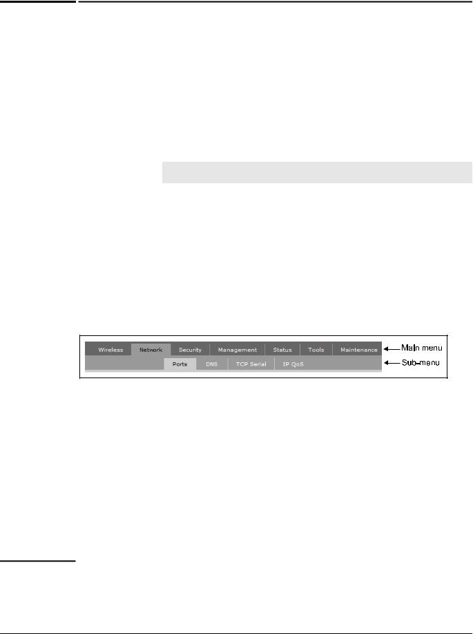
This guide uses specific syntax when directing you to interact with the management tool user interface. Refer to the following image for identification of key user-interface elements and then the table below for example directions:
Example directions in this guide |
What to do in the user interface |
|
|
Select Network > Ports |
On the main menu select Network and then |
|
select Ports on the sub-menu. |
|
|
For Password specify secret22. |
In the Password field enter the text secret22 |
|
exactly as shown. |
|
|
Warnings and cautions
Do not proceed beyond a WARNING or CAUTION notice until you fully understand the hazardous conditions and have taken appropriate steps.
Warning |
Identifies a hazard that can cause physical injury or death. |
1-2

|
|
|
Introduction |
|
|
|
About this guide |
|
|
|
|
Caution |
|
Identifies a hazard that can cause the loss of data or configuration information, create a non- |
|
|
|
compliant condition, or hardware damage. |
|
|
|
Commands and program listings |
|
|
|
||
|
|
Monospaced text identifies commands and program listings as follows: |
|
|
|
|
|
|
|
Example |
Description |
|
|
|
|
|
|
use-access-list |
Command name. Specify it as shown. |
|
|
|
|
|
|
ip_address |
Items in italics are parameters for which you must supply |
|
|
|
a value. |
|
|
|
|
|
|
ssl-certificate=URL [%s] |
Items enclosed in square brackets are optional. You can |
|
|
|
either include them or not. Do not include the brackets. |
|
|
|
In this example you can either include the “%s” or omit it. |
|
|
|
|
|
|
[ONE | TWO] |
Items separated by a vertical line indicate a choice. |
|
|
|
Specify only one of the items. Do not include the vertical |
|
|
|
line. |
|
|
|
|
1-3

Introduction
Introducing the M111 Client Bridge
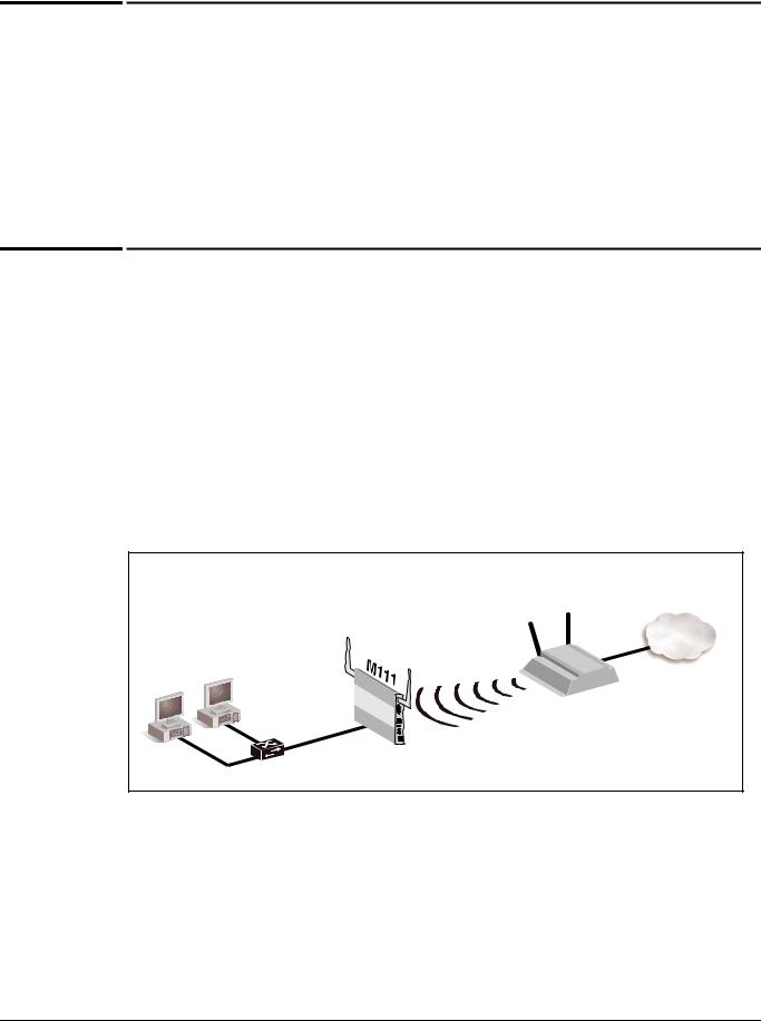
Introducing the M111 Client Bridge
The M111 connects legacy Ethernet or serial communications devices to a wireless local area network (WLAN) with simplicity and security. It enables the deployment of legacy client devices (such as electronic cash registers, servers, printers), in any location where a WLAN signal is available, eliminating the installation of a cabling infrastructure.
|
|
|
|
|
|
|
|
|
|
|
|
|
ss |
to network via wirel |
es |
s |
|
|
|
|
|
|
|
|
|
|
|
|
|
|
|||||
|
|
|
|
|
|
|
|
|
|
|
|
ce |
|
|
|
|
|
|
|
lin |
|
|
|
|
|
|
|
|
|
|
|
|
|
||
|
|
|
|
|
|
|
|
|
|
n |
ac |
|
|
|
|
|
|
|
|
|
k |
. |
|
|
|
|
|
|
|
|
|
|
|||
|
|
|
|
|
|
|
|
|
ai |
|
|
|
|
|
|
|
|
|
|
|
|
|
|
|
|
|
|
|
|
|
|
|
|
||
|
|
|
|
|
|
|
|
rs |
g |
|
|
|
|
|
|
|
|
|
|
|
|
|
|
|
|
|
|
|
|
|
|
|
|
|
|
|
|
|
|
|
|
|
te |
|
|
|
|
|
|
|
|
|
|
|
|
|
|
|
|
|
|
|
|
|
|
|
|
|
|
|
|
|
|
|
|
|
|
u |
|
|
|
|
|
|
|
|
|
|
|
|
|
|
|
|
|
|
|
|
|
|
|
|
|
|
|
|
|
|
|
|
|
|
p |
|
|
|
|
|
|
|
|
|
|
|
|
|
|
|
|
|
|
|
|
|
|
|
|
|
|
|
|
|
|
|
|
|
|
m |
|
|
|
|
|
|
|
|
|
|
|
|
|
|
|
|
|
|
|
|
|
|
|
|
|
|
|
|
|
|
|
|
|
|
o |
|
|
|
|
|
|
|
|
|
|
|
|
|
|
|
|
|
|
|
|
|
|
|
|
|
|
|
|
|
|
|
|
|
|
c |
|
|
|
|
|
|
|
|
|
|
|
|
|
|
|
|
|
|
|
|
|
|
|
|
|
|
|
|
|
|
|
|
|
|
d |
|
|
|
|
|
|
|
|
|
|
|
|
|
|
|
|
|
|
|
|
|
|
|
|
|
|
|
|
|
|
|
|
|
|
e |
|
|
|
|
|
|
|
|
|
|
|
|
|
|
|
|
|
|
|
|
|
|
|
|
|
|
|
|
|
|
|
|
|
|
|
ir |
|
|
|
|
|
|
|
|
|
|
|
|
|
|
|
|
|
|
|
|
|
|
|
|
|
|
|
|
|
|
|
|
|
|
|
W |
|
|
|
|
|
|
|
|
|
|
|
|
|
|
|
|
|
|
|
|
|
|
|
|
|
|
|
|
|
|
|
|
|
|
|
|
|
|
|
|
|
|
|
|
|
|
|
|
|
|
|
|
|
|
|
|
|
|
|
|
|
|
|
|
|
|
TCP/IP network |
||||
|
|
|
|
|
|
|
|
|
|
|
|
|
|
|
|
|
|
|
|
|
MSM AP |
|
|
|
|
|
|
|
|
|
|||||
Swtich |
|
|
|
|
|
|
|
|
|
|
|
|
|
|
|
|
|
|
|
|
|
|
|
|
|
|
|
|
|
|
|
|
|
|
|
|
|
|
|
|
|
|
|
|
|
|
|
|
|
|
|
|
|
|
|
|
|
|
|
|
|
|
|
|
|
|
|
|
|
|
Host computer |
Serial |
cable |
|
|
|
|
|
|
|
|
|
|
|
|
|
|
|
|
|
|
|
|
|
|
|
|
|
|
|
|
|
|
|
|||
|
|
|
|
|
|
|
|
|
|
|
|
|
|
|
|
|
|
|
|
|
|
|
|
|
|
|
|
|
|
|
|
|
|
||
|
|
|
|
|
Point-of-sale |
|
|
|
|
|
|
|
|
|
|
|
|
|
|
|
|
|
|
|
|
|
|
|
. |
||||||
|
|
|
|
|
|
|
terminal |
|
|
|
|
|
|
|
|
|
|
|
|
|
|
|
|
|
|
|
|
|
|
|
|
||||
|
|
|
|
|
|
|
|
|
|
|
|
|
|
|
|
|
|
|
|
|
|
|
|
|
|
|
|
|
|
|
rk |
||||
|
|
|
|
|
|
|
|
|
|
|
|
|
|
|
|
|
|
|
|
|
|
|
|
|
|
|
|
|
|
|
|
|
|
|
o |
|
|
|
|
|
|
|
|
|
|
|
|
|
|
|
|
|
|
|
|
|
|
|
|
|
|
|
|
|
|
|
|
|
|
w |
|
|
|
|
|
|
|
|
|
|
|
|
|
|
|
|
|
|
|
|
|
|
|
|
|
|
|
|
|
|
|
|
|
|
|
t |
|
|
|
|
|
|
|
|
|
|
|
|
|
|
|
|
|
|
|
|
|
|
|
|
|
|
|
|
|
|
|
|
|
|
|
e |
|
|
|
|
|
|
|
|
|
|
|
|
|
|
|
|
|
|
|
|
|
|
|
|
|
|
|
|
|
|
|
|
|
|
|
n |
|
|
|
|
|
|
|
|
|
|
|
|
|
|
|
|
|
|
|
|
|
|
|
|
|
|
|
|
|
|
|
|
|
|
|
P |
|
|
|
|
|
|
|
|
|
|
|
|
|
|
|
|
|
|
|
|
|
|
|
|
|
|
|
|
|
|
|
|
|
|
C |
|
|
|
|
|
|
|
|
|
|
|
|
|
|
|
|
|
|
|
|
|
|
|
|
|
|
|
|
|
|
|
|
|
|
T |
|
|
|
|
|
|
|
|
|
|
|
|
|
|
|
|
|
|
|
|
|
|
|
|
|
|
|
|
|
|
|
|
|
|
ia |
|
|
|
|
|
|
|
|
|
|
|
|
|
|
|
|
|
|
|
|
|
|
|
|
|
|
|
|
|
|
|
|
|
|
|
v |
|
|
|
|
|
|
|
|
|
|
|
|
|
|
|
|
|
|
|
|
|
|
|
|
|
|
|
|
|
|
|
|
|
|
t |
|
|
|
|
|
|
|
|
|
|
|
|
|
|
|
|
|
|
|
|
|
|
|
|
|
|
|
|
|
|
|
|
|
|
s |
|
|
|
|
|
|
|
|
|
|
|
|
|
|
|
|
|
S |
|
|
|
|
|
|
|
|
|
|
|
|
|
|
|
|
o |
|
|
|
|
|
|
|
|
|
|
|
|
|
|
|
|
|
|
eri |
|
|
|
|
|
|
|
|
|
|
|
|
|
|
e |
h |
|
|
|
|
|
|
|
|
|
|
|
|
|
|
|
|
|
|
|
|
al |
|
|
|
|
|
|
|
|
|
|
|
|
ot |
|
|
|
|
|
|
|
|
||
|
|
|
|
|
|
|
|
|
|
|
|
|
|
d |
evi |
ce |
|
d |
|
|
ith |
re |
|
|
|
|
|
|
|
|
|
|
|||
|
|
|
|
|
|
|
|
|
|
|
|
|
|
|
|
|
|
exchanges |
ata |
|
|
|
|
|
|
|
|
|
|
|
|
|
|
|
|
In this sample deployment, the M111 provides a wireless link to a TCP/IP network for a pair of desktop computers and a serial point-of-sale terminal. An MSM AP is used to create the wireless network.
Key features
Bridges an Ethernet LAN segment to a wireless network, providing connectivity for up to 20 client devices that run IPV4 and a single client device running a legacy networking protocol, such as DECnet, IPX, or Appletalk.
Provides an integrated serial-to-TCP/IP converter which enables a TIA-232 asynchronous terminal device to communicate with a compatible station over a wireless network.
802.11b a/b/g radio supporting antenna diversity.
Provides enhanced security using configurable Ethernet MAC and bidirectional Layer 2 and Layer 3 protocol filters.
Ensures wireless network privacy using WPA2, WPA, and WEP security and high performance hardware-assisted AES, TKIP, WEP encryption.
Provides 802.1X, PEAP, EAP-TLS, EAP-FAST, and EAP-TTLS authentication.
Features a rugged, plenum-rated metal enclosure.
1-4

Warning
Introduction
Safety information
Safety information
Professional Installation Required
Prior to installing or using an M111, consult with a professional installer trained in RF installation and knowledgeable in local regulations including building and wiring codes, safety, channel, power, indoor/outdoor restrictions, and license requirements for the intended country. It is the responsibility of the end user to ensure that installation and use comply with local safety and radio regulations.
Surge protection and grounding: If you plan on connecting an outdoor antenna to an M111, make sure that proper lightning surge protection and grounding precautions are taken according to local electrical code. Failure to do so may result in personal injury, fire, equipment damage, or a voided warranty. The HP ProCurve hardware warranty provides no protection against damage caused by static discharge or a lightning strike.
Cabling: You must use the appropriate cables, and where applicable, surge protection, for your given region. For compliance with EN55022 Class-B emissions requirements use shielded Ethernet cables.
Country of use: In some regions, you are prompted to select the country of use during setup. Once the country has been set, the M111 will automatically limit the available wireless channels, ensuring compliant operation in the selected country. Entering the incorrect country may result in illegal operation and may cause harmful interference to other systems.
Safety: Take note of the following safety information during installation:
If your network covers an area served by more than one power distribution system, be sure all safety grounds are securely interconnected.
Network cables may occasionally be subject to hazardous transient voltages (caused by lightning or disturbances in the electrical power grid).
Handle exposed metal components of the network with caution.
An M111 and all interconnected equipment must be installed indoors within the same building (except for outdoor models / antennas), including all PoE-powered network connections as described by Environment A of the IEEE 802.3af standard.
Servicing
There are no user-serviceable parts inside HP ProCurve Networking products. Any servicing, adjustment, maintenance, or repair must be performed only by trained service personnel.
1-5

Introduction
HP ProCurve Networking support
HP ProCurve Networking support
HP ProCurve Networking offers support 24 hours a day, seven days a week through a number of automated electronic services. See the Customer Support/Warranty booklet included with your product.
The HP ProCurve Networking Web site, www.hp.com/go/procurve/support provides up-to- date support information.
Additionally, your HP-authorized network reseller can provide you with assistance, both with services that they offer and with services offered by HP.
Before contacting support
To make the support process most efficient, before calling your networking dealer or HP Support, you first should collect the following information:
Collect this information |
Where to find it |
|
|
Product identification. |
On the rear of the product. |
|
|
Software version. |
The M111 management tool Login page. |
|
|
Network topology map, including the |
Your network administrator. |
addresses assigned to all relevant devices. |
|
|
|
Online documentation
For the latest documentation, visit the HP ProCurve Networking manuals Web page at: www.hp.com/go/procurve/manuals.
1-6

2
Getting started
Contents
Deploying the M111 ..................................................................................................... |
2-2 |
Scenario 1: Connecting wired devices to a wireless network ................................ |
2-2 |
Overview................................................................................................................. |
2-2 |
Configuration procedure ...................................................................................... |
2-3 |
Scenario 2: Connecting a wired device using MAC address cloning ..................... |
2-8 |
Overview................................................................................................................. |
2-8 |
Configuration procedure ...................................................................................... |
2-9 |
Scenario 3: Connecting a serial device to a wireless network ............................. |
2-11 |
Overview............................................................................................................... |
2-11 |
Configuration procedure .................................................................................... |
2-12 |
Getting started
Deploying the M111
Deploying the M111
This chapter provides step-by-step instructions that explain how to configure the M111 for the following frequently used deployments.
Scenario 1: Connecting wired devices to a wireless network on page 2-2
Scenario 2: Connecting a wired device using MAC address cloning on page 2-8
Scenario 3: Connecting a serial device to a wireless network on page 2-11
Scenario 1: Connecting wired devices to a wireless network
This scenario explains how to use the M111 to connect several wired devices to a network via a wireless link.
Overview
In this scenario, the M111 connects two wired computers to a private network via a wireless connection. The two computers are linked to a hub or switch which is plugged into Port 1 on the M111. Once connected to the private network via the wireless link, the computers obtain an IP address from the DHCP server and can then communicate with resources on the private network.
|
|
|
|
Private network with |
|
|
|
MSM AP |
DHCP server on |
|
|
|
subnet 192.168.5.0 |
|
|
|
|
|
5.25 |
|
|
|
5.25 |
|
5.27 |
Port |
1 |
5.11 |
|
|
|
|||
|
5.11 |
|
||
5.26 |
|
|
|
|
|
|
|
|
|
|
Switch/Hub |
|
|
|
(Although this scenario shows two connected devices, up to 20 Ethernet devices can share the wireless link, with each device getting its own unique IP address from the DHCP server.)
This scenario assumes that:
The M111 is in its factory-default state.
A DHCP server is operating on the private network, assigning addresses on the subnet 192.168.5.0.
2-2
Getting started
Scenario 1: Connecting wired devices to a wireless network
The MSM AP is operating in autonomous mode in its factory-default configuration. (As such, it obtains an IP address of 5.25 from the DHCP server and creates a wireless network call HP ProCurve.) Install the MSM AP as described in its Quickstart.
The wired computers are configured to obtain their IP addresses automatically (DHCP clients).
Configuration procedure
Configuration of the M111 occurs via its Web-based management tool. To access this tool you need a computer running at least Microsoft Internet Explorer 7/8 or Firefox 3.x.
Note |
Do not power on the M111 until directed. |
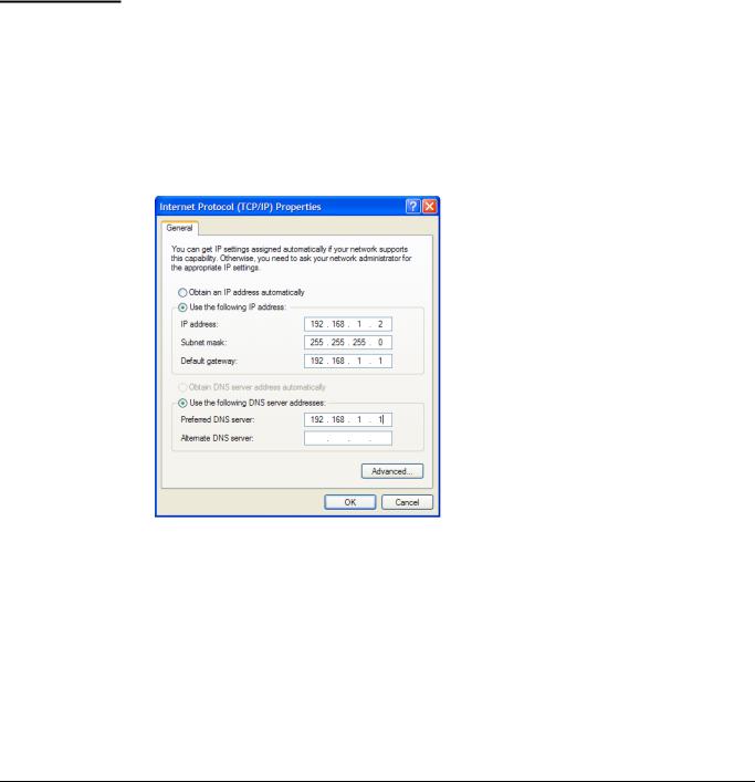
A. Configure your computer
1.Configure the LAN port on a computer to use the static IP address 192.168.1.2 with a subnet mask of 255.255.255.0. Set the default gateway to 192.168.1.1, and DNS server to 192.168.1.1.
For example, in Windows XP, select Control Panel > Network Connections > Local Area Connection > Properties > Internet Protocol (TCP/IP) > Properties.
2. Disable any wireless connection.
2-3
Getting started
Scenario 1: Connecting wired devices to a wireless network
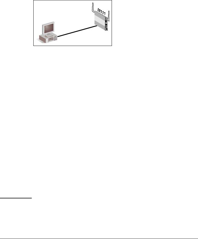
B. Connect to the M111
Connect the LAN port on the computer to the Ethernet port on the M111 using a standard Ethernet cable. (If your computer has an older 10BaseT-only Ethernet interface, then use a crossover cable instead.)
|
|
|
Port |
1 |
|
|
|
|
|
.1 |
|
|
|
|
|
|
|
|
|
|
|
.1 |
|
|
|
|
.168 |
|
|
LAN |
port |
.2 |
192 |
|
|
|
|
|
|||
|
|
|
|
||
|
.1 |
|
|
|
|
|
.168 |
|
|
|
|
192 |
|
|
|
|
|
C. Start the M111
Power on the M111 using one of the following methods.
• A PoE-enabled switch. Various PoE-enabled switches are available from HP ProCurve.
• An HP ProCurve PoE 1-Port Power Injector (J9407A)
• An HP ProCurve MSM31x Power Supply (J9405A). This scenario uses this method. Proceed to the next step once the Power light stops blinking and remains on.
D. Connect to the management tool and login
1.Open a web browser on the computer and specify the address: https://192.168.1.1.
2.A security certificate warning is displayed the first time that you connect to the management tool. This is normal. Select whatever option is needed in your Web browser to continue to the management tool. The security warning will not appear again unless you change the IP address of the M111.
To eliminate the security warning, you need to replace the default certificate that is installed on the M111. See About certificate warnings on page 3-43.
3.On the Login page, specify admin for both Username and Password and then select
Login.
4.On the License Agreement page, read and then select Accept License Agreement.
5.The Registration page appears. It is recommended that you register later by selecting
Maintenance > Registration.
6.If a Country prompt appears, select the country in which the M111 will operate.
Caution |
Once the country has been set, the M111 will automatically limit the available wireless |
|
channels, ensuring compliant operation in the selected country. Entering the incorrect |
|
country may result in illegal operation and may cause harmful interference to other |
|
systems. |
|
|
2-4
Getting started
Scenario 1: Connecting wired devices to a wireless network
7.At the password prompt it is recommended that you change the default password. Enter the new password and select Save.
About |
The default username and password is admin. New passwords must be 6 to 16 printable |
passwords |
ASCII characters in length with at least 4 different characters. Passwords are case sensitive. |
|
Space characters and double quotes ( “ ) cannot be used. Passwords must also conform to the |
|
selected security policy as described in Security policies on page 3-6. |
|
|
E. Set the M111 IP address
By default the M111 operates as a DHCP client on both the Ethernet port and the Wireless port. Once it establishes a connection with a DHCP server via either port, it will receive a new IP address from the DHCP server address pool, and the management tool will no longer be accessible at the default address of 192.168.1.1. To maintain access to the management tool at a known IP address, you can use one of the following strategies:
Pre-configure the DHCP server on the network to assign a specific IP address to the M111. To do this you need to specify the M111 MAC address and a reserved IP address on the DHCP server. The M111 MAC address is printed on the M111 label identified as Wireless Base MAC, or listed on the management tool Home or Login page as
Wireless MAC address.
Define a management address. This is a secondary IP address on which the management tool can be reached. See To assign a management address on page 3-34.
Assign a static IP address to the M111 as follows:
1.Select Network > DNS.
2.Under DNS servers, set Server to the IP address of the DNS server on the private network.
3.Select Network > Ports > Bridge port.
4.Under Assign IP address via, select Static and then Configure.
5.Under Port settings, configure the following settings:
IP address: Set the IP address on the same subnet as the MSM AP to which the M111 will connect once installed. Respect any DHCP server-mandated static address ranges. For this scenario, use 192.168.5.11.
Mask: Set the corresponding mask for the IP address. This scenario uses the mask 255.255.255.0.
Default gateway: Set the IP address of the gateway on the network.
2-5
Getting started
Scenario 1: Connecting wired devices to a wireless network
6.Select Save. The IP address of the M111 will immediately change, causing you to lose your connection to the management tool. This is normal. To re-establish the connection, configure the computer with a static IP address on the same subnet as the M111. For this scenario, use 192.168.5.12.
|
|
|
Port |
1 |
|
|
|
.11 |
|
|
|
|
|
|
|
|
|
|
.5 |
|
port |
|
.168 |
|
LAN |
.12 |
192 |
|
|
|
|
|
||
|
|
|
|
|
|
.5 |
|
|
|
.168 |
|
|
|
|
192 |
|
|
|
|
7.Re-launch the management tool by browsing to the new IP address assigned to the M111: https://192.168.5.11.
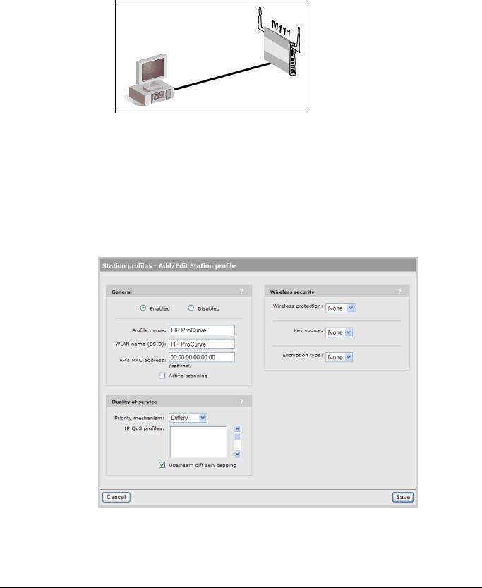
F.Configure a station profile
A station profile contains the settings that the M111 uses to establish a connection with a wireless network. This section explains how to customize the default station profile that is pre-configured on the M111.
1.Select Wireless > Station profiles and select the HP ProCurve profile in the table. The
Add/Edit Stations profile page opens.
2-6

Getting started
Scenario 1: Connecting wired devices to a wireless network
2.Under General, configure settings as follows:
Select Enabled.
Profile name: The Profile name is just a friendly name used for display purposes. You can use the default value.
WLAN name (SSID): This is the name of the wireless network that to which the M111 will attempt to connect. By default, the M111 uses the WLAN name HP ProCurve, which is the default name used by MSM APs. If you are using your own name, define the same name on both the M111 and the MSM AP.
AP’s MAC address: Leave this set to its default value.
Active scanning: If the MSM AP to which the M111 will connect does not broadcast its WLAN name (SSID), you will have to enable this option for the M111 to successfully connect. By default, MSM APs broadcast their SSID, and this option does not need to be enabled.
3.Under Wireless security, select the Authentication type and Encryption type that are configured on the MSM AP to which the M111 will connect. You must define the same security settings on both the M111 and on the MSM AP. By default, MSM APs do not have security enabled.
Caution |
It is strongly recommended that wireless security settings be enabled on the |
|
MSM AP and the M111 to safeguard traffic on the wireless network. |
|
|
4.Select Save. The M111 automatically attempts to establish a wireless connection with the MSM AP. To check the status of the connection, select Wireless > Overview. The
Station State should indicate Associated.
Once the wireless connection is established, the M111 is ready for operation, and can transport traffic from connected devices across the wireless link. In addition, access to the M111 management tool is now possible across the wireless link.
G. Connect the wired computers to the M111
Connect the wired computers to a switch/hub and plug the switch/hub into Port 1 on the M111. The computers should be configured to obtain their IP addresses automatically (DHCP client).
Start up a wired computer. It will receive an IP address from the DHCP server on the private network (for example, 192.168.5.26). The computer can now exchange data with the private network.
2-7
Getting started
Scenario 2: Connecting a wired device using MAC address cloning
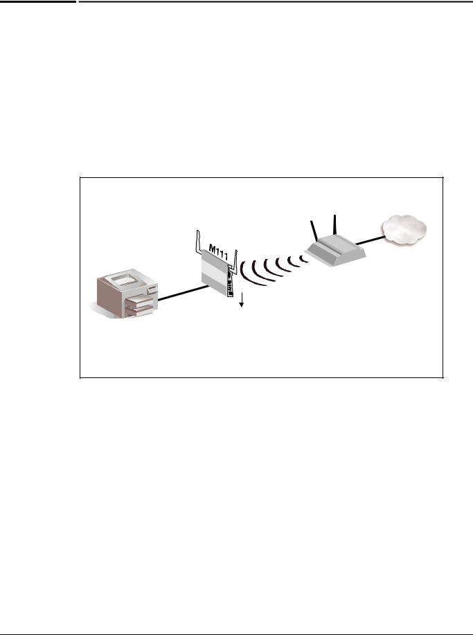
Scenario 2: Connecting a wired device using MAC address cloning
This scenario explains how to connect a single wired device to a wireless network using the M111’s Ethernet MAC cloning feature.
Overview
In this scenario, a wired printer is converted to wireless access. Since the printer is already known by users on the network, the MAC cloning feature is used to preserve the printer’s network identity. This enables users to maintain access to the printer without changing their settings.
Printer
Port |
1 |
|
5.11
5.10
MAC address 21:33:AB:FE:36:82
Static IP address 192.168.5.10
|
Private network with |
|
MSM AP |
DHCP server on |
|
subnet 192.168.5.0 |
||
|
5.25
5.25
5.11
Replaced by: Cloned MAC address 21:33:AB:FE:36:82 and
Cloned IP address 192.158.5.10
This scenario assumes that:
The M111 is in its factory-default state.
A DHCP server is operating on the private network, assigning addresses on the subnet 192.168.5.0
The MSM AP is operating in autonomous mode in its factory default configuration. (As such, it obtains an IP address of 5.25 from the DHCP server and creates a wireless network call HP ProCurve.) Install the MSM AP as described in its Quickstart.
The printer is configured with a static IP address of 192.168.5.10.
2-8
Getting started
Scenario 2: Connecting a wired device using MAC address cloning
Configuration procedure
The initial configuration steps for this scenario are the same as for Scenario 1. For each step see the instructions on the indicated page.
A. Configure your computer
See Configure your computer on page 2-3.
B. Connect to the M111
See Connect to the M111 on page 2-4.
C. Start the M111
See Start the M111 on page 2-4.
D. Connect to the management tool and login
See Connect to the management tool and login on page 2-4.
E. Set the M111 IP address
See Set the M111 IP address on page 2-5.
F. Configure a station profile
See Configure a station profile on page 2-6.
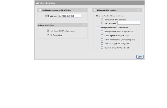
G. Configure MAC cloning options
1. Select Wireless > Bridging. The Wireless bridging page opens.
2-9

Getting started
Scenario 2: Connecting a wired device using MAC address cloning
2.Select Ethernet MAC cloning, then configure the following options:
Select the Discovered MAC address option. This option causes the M111 to take the MAC address of the wired device that is connected to Port 1 (the printer) and assign it to the Wireless port. Once this is done, the M111 re-associates with the MSM AP using the current station profile.
A limitation of MAC cloning is that once the cloned MAC address is used to establish the wireless connection, the M111 itself is no longer accessible through the wireless port. To enable support for wireless access to the management tool, select Management tool (TCP port 443). Note that to reach the management tool you must use the IP address assigned to the cloned device (5.10) and not the IP address assigned to the M111 (5.11). For information on the other interception options, see
Setting up management traffic interception on page 3-32.
3.Select Save.
H. Connect the wired device to the M111
Connect the printer to Port 1 on the M111 using a standard Ethernet cable.
The M111 will automatically re-connect to the wireless network using the IP address 192.168.5.10. Computers on the private network should now be able to send print jobs to the printer.
To reach the M111 management tool from the private network, use the address 192.168.5.10.
2-10
Getting started
Scenario 3: Connecting a serial device to a wireless network
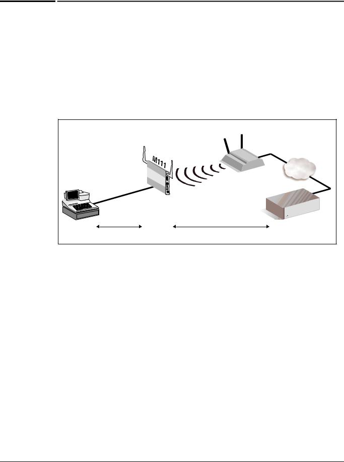
Scenario 3: Connecting a serial device to a wireless network
This scenario explains how to connect a serial device to a wireless network, enabling serial traffic to be sent to a remote host via TCP/IP.
Overview
In this scenario, the M111 enables a point-of-sale terminal to exchange traffic with a remote host. In addition to providing the connection to a wireless network, the M111 also converts traffic between serial and TCP/IP.
|
|
|
|
|
MSM AP |
Private network with |
|
|
|
|
|
|
|
|
|
|
|
|
|
DHCP server on |
|
|
|
|
|
|
subnet 192.168.5.0 |
|
|
|
|
|
|
5.25 |
|
|
|
|
|
5.25 |
|
|
Serial |
Port |
|
5.11 |
|
|
|
|
|
|
|||
|
Serial |
cable |
|
|
|
|
|
|
|
|
|
|
|
Point-of-sale |
Serial |
|
M111 |
TCP |
Host computer |
|
terminal |
|
TCP server |
TCP client |
|||
This scenario assumes that:
The M111 is in its factory-default state.
A DHCP server is operating on the private network, assigning addresses on the subnet 192.168.5.0
The MSM AP is operating in autonomous mode in its factory default configuration. (As such, it obtains an IP address of 5.25 from the DHCP server and creates a wireless network call HP ProCurve.) Install the MSM AP as described in its Quickstart.
The remote host is operating as a TCP client.
2-11
Loading...