


 Loading...
HP ProBook 430 G1 Notebook PC
Maintenance and Service Guide
© Copyright 2013 Hewlett-Packard
Development Company, L.P.
Bluetooth is a trademark owned by its proprietor and used by Hewlett-Packard Company under license. Intel and Core are trademarks or registered trademarks of Intel Corporation in the United States and other countries. Microsoft and Windows are either trademarks or registered trademarks of Microsoft Corporation in the United States and/or other countries. SD Logo is a trademark of its proprietor.
The information contained herein is subject to change without notice. The only warranties for HP products and services are set forth in the express warranty statements accompanying such products and services. Nothing herein should be construed as constituting an additional warranty. HP shall not be liable for technical or editorial errors or omissions contained herein.
First Edition: July 2013
Document Part Number: 726502-001
Product notice
This guide describes features that are common to most models. Some features may not be available on your computer.
Not all features are available in all editions of Windows 8. Your computer may require upgraded and/or separately purchased hardware, drivers, and/or software to take full advantage of Windows 8 functionality. See http://www.microsoft.com for details.

Important Notice about Customer Self-Repair Parts
CAUTION: Your computer includes Customer Self-Repair parts and parts that should only be accessed by an authorized service provider. See Chapter 5, "Removal and replacement procedures for Customer Self-Repair parts," for details. Accessing parts described in Chapter 6, "Removal and replacement procedures for Authorized Service Provider only parts," can damage the computer or void your warranty.
iii
iv Important Notice about Customer Self-Repair Parts

Safety warning notice
WARNING! To reduce the possibility of heat-related injuries or of overheating the computer, do not place the computer directly on your lap or obstruct the computer air vents. Use the computer only on a hard, flat surface. Do not allow another hard surface, such as an adjoining optional printer, or a soft surface, such as pillows or rugs or clothing, to block airflow. Also, do not allow the AC adapter to contact the skin or a soft surface, such as pillows or rugs or clothing, during operation. The computer and the AC adapter comply with the user-accessible surface temperature limits defined by the International Standard for Safety of Information Technology Equipment (IEC 60950).
v
vi Safety warning notice

Table of contents
1 |
Product description ........................................................................................................... |
1 |
2 |
External component identification ..................................................................................... |
6 |
|
Display - Windows models ........................................................................................................ |
6 |
|
Display - SLED models .............................................................................................................. |
8 |
|
Top ........................................................................................................................................ |
9 |
|
TouchPad ................................................................................................................. |
9 |
|
Lights (select models only) ........................................................................................ |
10 |
|
Buttons and fingerprint reader (select models only) ...................................................... |
11 |
|
Keys ...................................................................................................................... |
12 |
|
Front ..................................................................................................................................... |
13 |
|
Left ....................................................................................................................................... |
14 |
|
Right .................................................................................................................................... |
15 |
|
Bottom .................................................................................................................................. |
16 |
|
Service tag and PCID label ..................................................................................................... |
17 |
|
Service tag ............................................................................................................. |
17 |
|
PCID label .............................................................................................................. |
18 |
3 |
Illustrated parts catalog .................................................................................................. |
19 |
|
Computer major components ................................................................................................... |
19 |
|
Display components ............................................................................................................... |
22 |
|
Cable Kit .............................................................................................................................. |
23 |
|
Mass storage devices ............................................................................................................. |
24 |
|
Miscellaneous parts ................................................................................................................ |
25 |
|
Sequential part number listing .................................................................................................. |
26 |
4 |
Removal and replacement procedures preliminary requirements .................................... |
30 |
|
Tools required ....................................................................................................................... |
30 |
|
Service considerations ............................................................................................................ |
30 |
|
Plastic parts ............................................................................................................ |
30 |
|
Cables and connectors ............................................................................................ |
31 |
vii
|
Drive handling ........................................................................................................ |
31 |
|
Grounding guidelines ............................................................................................................. |
32 |
|
Electrostatic discharge damage ................................................................................. |
32 |
|
Packaging and transporting guidelines ....................................................... |
33 |
|
Workstation guidelines ............................................................................. |
33 |
|
Equipment guidelines ................................................................................ |
34 |
5 |
Removal and replacement procedures for Customer Self-Repair parts ............................. |
35 |
|
Component replacement procedures ........................................................................................ |
35 |
|
Battery ................................................................................................................... |
35 |
|
Keyboard ............................................................................................................... |
37 |
|
Hard drive ............................................................................................................. |
40 |
|
Service door ........................................................................................................... |
43 |
|
SIM ....................................................................................................................... |
44 |
|
Memory modules .................................................................................................... |
45 |
|
WWAN module ..................................................................................................... |
46 |
|
WLAN/Bluetooth combo card .................................................................................. |
48 |
6 |
Removal and replacement procedures for Authorized Service Provider parts .................. |
50 |
|
Component replacement procedures ........................................................................................ |
50 |
|
Top cover ............................................................................................................... |
50 |
|
RTC battery ............................................................................................................ |
55 |
|
Fingerprint reader board .......................................................................................... |
56 |
|
Audio board ........................................................................................................... |
58 |
|
Function board ....................................................................................................... |
59 |
|
Power button board ................................................................................................. |
60 |
|
Speaker assembly ................................................................................................... |
62 |
|
Display assembly .................................................................................................... |
64 |
|
Power connector cable ............................................................................................ |
70 |
|
System board ......................................................................................................... |
71 |
|
Heat sink ............................................................................................................... |
74 |
7 |
Computer Setup (BIOS) and Advanced System Diagnostics .............................................. |
76 |
|
Windows 7 – Computer Setup (BIOS) and Advanced System Diagnostics ..................................... |
76 |
|
Using Computer Setup ............................................................................................. |
76 |
|
Starting Computer Setup ........................................................................... |
76 |
|
Navigating and selecting in Computer Setup ............................................... |
77 |
|
Restoring factory settings in Computer Setup ................................................ |
77 |
|
Updating the BIOS ................................................................................... |
78 |
|
Downloading SoftPaqs to update the BIOS ................................... |
78 |
viii
BIOS management using system diagnostics ................................. |
78 |
Using f10 setup to update the BIOS ............................................. |
79 |
Determining the BIOS version ..................................................... |
79 |
Downloading a BIOS update ...................................................... |
80 |
BIOS Setup Menu ..................................................................................... |
80 |
Main menu ............................................................................... |
81 |
Security menu ........................................................................... |
81 |
Diagnostics menu ...................................................................... |
81 |
Using Advanced System Diagnostics ......................................................................... |
81 |
Windows 8 – Computer Setup (BIOS) and Advanced System Diagnostics ..................................... |
83 |
Using Computer Setup ............................................................................................. |
83 |
Starting Computer Setup ........................................................................... |
83 |
Navigating and selecting in Computer Setup ............................................... |
83 |
Restoring factory settings in Computer Setup ................................................ |
84 |
Updating the BIOS ................................................................................... |
84 |
Determining the BIOS version ..................................................... |
85 |
Downloading a BIOS update ...................................................... |
85 |
Using MultiBoot ...................................................................................................... |
86 |
About the boot device order ...................................................................... |
86 |
Choosing MultiBoot preferences ................................................................. |
86 |
Setting a new boot order in Computer Setup ................................ |
87 |
Dynamically choosing a boot device using the f9 prompt ............... |
87 |
Setting a MultiBoot Express prompt .............................................. |
87 |
Entering MultiBoot Express preferences ........................................ |
88 |
Using System Diagnostics ......................................................................................... |
88 |
SLED – Computer Setup (BIOS) and Advanced System Diagnostics ............................................... |
90 |
Starting Computer Setup .......................................................................................... |
90 |
Using Computer Setup ............................................................................................. |
90 |
Navigating and selecting in Computer Setup ............................................... |
90 |
Restoring factory settings in Computer Setup ................................................ |
91 |
Updating the BIOS .................................................................................................. |
91 |
Determining the BIOS version .................................................................... |
92 |
Downloading a BIOS update ..................................................................... |
92 |
Using Advanced System Diagnostics ......................................................................... |
93 |
8 Specifications .................................................................................................................. |
94 |
Computer specifications .......................................................................................................... |
94 |
33.8-cm (13.3-in), HD display specifications ............................................................................. |
95 |
Hard drive specifications ........................................................................................................ |
96 |
Specification information in Device Manager ............................................................................ |
97 |
ix
9 Backup and recovery in Windows 7 ............................................................................... |
98 |
|
|
Creating recovery media with HP Recovery Disc Creator ............................................................ |
99 |
|
Creating recovery media .......................................................................................... |
99 |
|
Backing up your information .................................................................................................... |
99 |
|
Performing a system recovery ................................................................................................ |
100 |
|
Using the Windows recovery tools .......................................................................... |
100 |
|
Using f11 recovery tools ........................................................................................ |
101 |
|
Using a Windows 7 operating system DVD (purchased separately) ............................. |
102 |
10 Backup and recovery in Windows 8 ........................................................................... |
103 |
|
|
Backing up your information .................................................................................................. |
103 |
|
Performing a system recovery ................................................................................................ |
104 |
|
Using the Windows recovery tools .......................................................................... |
104 |
|
Using f11 recovery tools ........................................................................................ |
105 |
|
Using Windows 8 operating system media (purchased separately) .............................. |
106 |
|
Using Windows Refresh for quick and easy recovery ................................................. |
106 |
|
Remove everything and reinstall Windows ............................................................... |
107 |
|
Using HP Software Setup ....................................................................................... |
108 |
11 Backup and Recovery in SLED ..................................................................................... |
109 |
|
|
Creating backups ................................................................................................................. |
109 |
|
Backing up your information .................................................................................................. |
109 |
|
Performing a system recovery ................................................................................................ |
110 |
|
USB Recovery option (select models only) ................................................................................ |
111 |
|
Remove everything and reinstall SLED ..................................................................................... |
112 |
12 |
Statement of Volatility ................................................................................................ |
113 |
|
Non-volatile memory usage ................................................................................................... |
115 |
|
Questions and answers ......................................................................................................... |
117 |
13 |
Power cord set requirements ...................................................................................... |
118 |
|
Requirements for all countries and regions ............................................................................... |
118 |
|
Requirements for specific countries and regions ....................................................................... |
119 |
14 |
Recycling .................................................................................................................... |
121 |
|
Battery ................................................................................................................................ |
121 |
|
Display ............................................................................................................................... |
121 |
Index ............................................................................................................................... |
127 |
|
x
1 Product description
Category |
Description |
|
|
Product Name |
HP ProBook 430 G1 Notebook PC |
|
|
Processors |
All processors soldered onto system board. |
|
|
|
Intel® Core™ i7-4500U, 1.80-GHz/3.0-GHz core turbo, 4-MB L3 cache/Intel HD |
|
Graphics 4400 |
|
|
|
Intel Core i5-4250U, 1.30-GHz/2.6-GHz core turbo, 3-MB L3 cache/Intel HD |
|
Graphics 5000 |
|
|
|
Intel Core i5-4200U, 1.60-GHz/2.6-GHz core turbo, 3-MB L3 cache/Intel HD |
|
Graphics 4400 |
|
|
|
Intel Core i3-4010U, 1.70-GHz, 3-MB L3 cache/Intel HD Graphics 4400 |
|
|
Chipset |
Intel Shark Bay ULT |
|
|
Graphics |
Intel HD Graphics (UMA) |
|
Branding is processor-specific. |
|
|
Panel |
33.8-cm (13.3-inch) HD, anti-glare, LED, 1366x768, flat (3.6 mm), SVA, 200 nits, |
|
includes camera, with or without WWAN |
|
|
Memory |
Two customer-accessible/upgradeable memory module slots supporting up to 16 GB |
|
of RAM |
|
|
|
Supports dual-channel memory |
|
|
|
PC3-12800, 1600-MHz, DDR3L |
|
|
|
Supports the following configurations: |
|
● 16384 (8192 × 2; dual channel) |
|
● 12288 (8192 + 4096; dual channel) |
|
● 8192 (8192 × 1) |
|
● 8192 (4096 × 2; dual channel) |
|
● 6144 (4096 + 2048; dual channel) |
|
● 4096 (2048 × 2; dual channel) |
|
● 4096 (4096 × 1) |
|
● 2048 (2048 × 1) |
|
|
1

Category |
Description |
|
|
|
|
Hard drives |
Supports 7-mm, 6.35-cm (2.50-in) SATA hard drives with HP 3D DriveGuard |
|
|
|
|
|
Customer-accessible |
|
|
|
|
|
Supports the following hard drives: |
|
|
● |
500-GB, 7200-rpm |
|
● |
500-GB, 5400-rpm |
|
● |
320-GB, 5400-rpm |
|
|
|
|
Supports the following solid-state drives (SSDs): |
|
|
● 128-GB, SATA III |
|
|
|
|
Optical drives |
Supports external USB drive |
|
|
|
|
Audio/Visual |
Integrated dual-array microphone |
|
|
|
|
|
HD audio with DTS Sound+ |
|
|
|
|
|
Stereo speakers (2) |
|
|
|
|
|
Integrated webcam (720p HD) |
|
|
|
|
|
IDT 92HD91 |
|
|
|
|
|
Skype ready |
|
|
|
|
|
Headphone and microphone jacks |
|
|
|
|
Ethernet |
Realtek RTL8151FH-CG 10/100/1000 |
|
|
|
|
|
S3/S4/S5 wake on LAN (both AC and battery mode) |
|
|
|
|
Wireless |
Integrated WLAN options by way of wireless module: |
|
|
|
|
|
Two WLAN antennas built into display assembly |
|
|
|
|
|
Supports “no WLAN/No BT” option |
|
|
|
|
|
Supports the following WLAN formats: |
|
● Realtek RTL8188EE 802.11bgn Wi-Fi Adapter
● Mediatek MT7630E 802.11bgn Wi-Fi Adapter and Mediatek Bluetooth 4.0
Adapter
● Intel Dual Band Wireless-N 7260AN 802.11 a/b/g/n 2x2 WiFi + BT4.0
● Broadcom BCM943228HMB 802.11abgn 2x2 Wi-Fi + BT 4.0 Combo Adapter
● Atheros AR9485 802.11b/g/n 1x1 WiFi Adapter
● Atheros AR9565 802.11bgn 1x1 WiFi + BT4.0 combo Adapter
Integrated WWAN options by way of wireless module:
Two WWAN antennas built into display assembly (world-wide 5 band, configured with panels)
Subscriber identity module (SIM) security
2 |
Chapter 1 Product description |

Category |
Description |
|
|
|
Supports “no WWAN” option |
|
|
|
Supports the following WWAN modules: |
|
● HP lt4112 LTE/HSPA+ Gobi 4G Module |
|
● HP hs3110 HSPA+ Mobile Broadband Module |
|
|
|
Integrated personal area network (PAN) options by way of WLAN/ |
|
Bluetooth® combo card: |
|
|
|
Bluetooth 4.0 only supported by combo card |
|
|
External media card |
Digital Media Reader Slot |
|
|
Ports |
Audio-in (stereo microphone) |
|
|
|
Audio-out (stereo headphone) |
|
|
|
RJ-45 (Ethernet, includes link and activity lights) |
|
|
|
USB 3.0 (2) |
|
|
|
USB 2.0 powered (1) |
|
|
|
VGA (Dsub 15-pin) supporting 1600 × 1200 external resolution at 75-GHz (hot |
|
plug/unplug with auto-detect) |
|
|
|
HDMI |
|
|
|
Multi-pin AC port |
|
|
Keyboard/pointing devices |
Full-sized chiclet keyboard |
|
|
|
Touchpad includes: supports 2-way scroll with legend, taps enabled by default, 2- |
|
finger scrolling and zoom enabled by default |
|
|
Power requirements |
Smart AC adapter with localized cable plug support (3-wire plug with ground pin): |
|
|
|
65-W (for India and the People’s Republic of China) |
|
|
|
45-W |
|
|
|
4-cell, 44-Wh, 3.0 Ah Li-ion battery (In-line cavity) |
|
|
Security |
Integrated fingerprint reader |
|
|
|
Intel AT support |
|
|
|
Support security lock |
|
|
|
Support no fingerprint reader option |
|
|
Operating system |
Preinstalled: |
|
|
|
Windows 7 Professional 64 |
|
|
|
Windows 7 Professional 64 – MSNA |
|
|
|
Windows 7 Home Premium 64 |
|
|
|
Windows 7 Home Basic 64 |
|
|
3

Category |
Description |
|
|
|
|
|
Windows 8 Professional 64-bit Digital Product Key (DPK) with Windows 7 |
|
|
Professional 64 |
|
|
|
|
|
Windows 8 Professional 64-bit |
|
|
|
|
|
Windows 8 Multi-language (ML) 64-bit |
|
|
|
|
|
Windows 8 Emerging Markets (EM) 64-bit |
|
|
|
|
|
Windows 8 Chinese Markets (CH) 64-bit |
|
|
|
|
|
Novell™: SuSE Linux™ – SLED 11, 64-bit, SP2 (not available with WWAN) |
|
|
|
|
|
FreeDOS |
|
|
|
|
|
Windows 8 Professional 64-bit with Office 2010 Professional |
|
|
|
|
|
Restore Media: |
|
|
|
|
|
DRDVD/SRDVD: |
|
|
● |
DRDVD Windows 7 |
|
● |
DRDVD Windows 8 |
|
● SRDVD SuSE Linux Enterprise (SLED) Service Pack 2, 64-bit |
|
|
|
|
|
OSDVD: |
|
|
● Windows 7 Home Basic 64 |
|
|
● Windows 7 Home Premium 64 |
|
|
● Windows 7 Professional 32 |
|
|
● Windows 7 Professional 64 |
|
|
● Windows 8 Professional 64 |
|
|
|
|
|
Web-only support: |
|
|
|
|
|
Windows 7 Home Basic 32 |
|
|
|
|
|
Windows 7 Home Premium 32 |
|
|
|
|
|
Windows 7 Professional 32 |
|
|
|
|
|
Certified: |
|
|
|
|
|
Microsoft WHQL |
|
|
|
|
|
SuSE Linux Enterprise (SLED) Service Pack 2, 64-bit |
|
|
|
|
Serviceability |
End-user replaceable parts: |
|
|
|
|
|
AC adapter |
|
|
|
|
|
Battery (system) |
|
|
|
|
|
Hard drive |
|
|
|
|
|
Memory module |
|
|
|
|
4 |
Chapter 1 Product description |

Category |
Description |
|
|
|
WLAN module |
|
|
|
WWAN module, SIM |
|
|
|
Keyboard |
|
|
5

2 External component identification
Display - Windows models
Component |
Description |
|
|
|
|
(1) |
WLAN antennas (2)* (select models only) |
Send and receive wireless signals to communicate with wireless |
|
|
local area networks (WLAN). |
(2)WWAN antennas (2)* (select models only)
Send and receive wireless signals to communicate with wireless wide area networks (WWAN).
(3) |
Internal microphones (2) |
Record sound. |
|
|
|
(4) |
Webcam light |
On: The webcam is in use. |
|
|
|
6 |
Chapter 2 External component identification |

Component |
Description |
|
|
|
|
(5) |
Webcam |
Records video and captures still photographs. |
|
|
For information on using the webcam, access HP Support |
|
|
Assistant. To access HP Support Assistant on the Start screen, |
|
|
select the HP Support Assistant app. |
|
|
|
(6) |
Internal display switch |
Turns off the display or initiates Sleep if the display is closed |
|
|
while the power is on. |
NOTE: The display switch is not visible on the outside of the computer.
*The antennas are not visible on the outside of the computer. For optimal transmission, keep the areas immediately around the antennas free from obstructions. To see wireless regulatory notices, see the section of the Regulatory, Safety, and Environmental Notices that applies to your country or region. To access the user guides, select the HP Support Assistant app on the Start screen, select My computer, and then select User guides.
Display - Windows models |
7 |
 E3U93UTABA, E3U87UTABA, E3U85UTABA User Manual")
Display - SLED models
Component |
Description |
|
|
|
|
(1) |
WLAN antennas (2)* (select models only) |
Send and receive wireless signals to communicate with wireless |
|
|
local area networks (WLAN). |
|
|
|
(2) |
Internal microphones (2) |
Record sound. |
|
|
|
(3) |
Webcam light |
On: The webcam is in use. |
|
|
|
(4) |
Webcam |
Records video and captures still photographs. |
|
|
|
(5) |
Internal display switch |
Turns off the display or initiates Suspend if the display is closed |
|
|
while the power is on. |
NOTE: The display switch is not visible from the outside of the computer.
*The antennas are not visible from the outside of the computer. For optimal transmission, keep the areas immediately around the antennas free from obstructions. To see wireless regulatory notices, see the section of the Regulatory, Safety, and Environmental Notices that applies to your country or region.
8 |
Chapter 2 External component identification |
Top
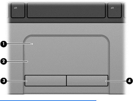
TouchPad
Component |
|
Description |
|
|
|
(1) |
TouchPad on/off button |
Turns the TouchPad on and off. |
|
|
|
(2) |
TouchPad zone |
Moves the pointer and selects or activates items on the |
|
|
screen. |
|
|
|
(3) |
Left TouchPad button |
Functions like the left button on an external mouse. |
|
|
|
(4) |
Right TouchPad button |
Functions like the right button on an external mouse. |
|
|
|
Top 9
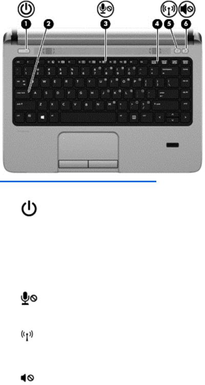
Lights (select models only)
Component |
|
Description |
|
|
|
(1) |
Power light |
● On: The computer is on. |
|
|
● Blinking: The computer is in the Sleep state (Windows 8) |
|
|
or Suspend state (SLED). |
|
|
NOTE: The elapsed time between blinks is longer than |
|
|
on previous models. |
|
|
● Off: The computer is off (Windows 8) or in Hibernation |
|
|
(SLED). |
|
|
|
(2) |
Caps lock light |
On: Caps lock is on. |
|
|
|
(3) |
Microphone mute light |
Amber: Microphone is off. |
|
|
|
(4) |
Num lock light |
On: Num lock is on. |
|
|
|
(5) |
Wireless light (select models only) |
● White: An integrated wireless device, such as a wireless |
|
|
local area network (WLAN) device and/or a |
|
|
Bluetooth® device, is on. |
|
|
● Amber: All wireless devices are off. |
|
|
|
(6) |
Mute light |
● Amber: Computer sound is off. |
|
|
● White: Computer sound is on. |
|
|
|
10 |
Chapter 2 External component identification |
Buttons and fingerprint reader (select models only)
Component |
|
Description |
|
|
|
(1) |
Power button |
● When the computer is off, press the button to turn on the |
|
|
computer. |
|
|
● (Windows 8) When the computer is in the Sleep state, |
|
|
press the button briefly to exit Sleep. |
|
|
● (SLED) When the computer is in the Suspend state, press |
|
|
the button briefly to exit Suspend. |
|
|
● (SLED) When the computer is on, press the button briefly |
|
|
to initiate Suspend. |
|
|
● When the computer is in Hibernation, press the button |
|
|
briefly to exit Hibernation. |
|
|
CAUTION: Pressing and holding down the power button |
|
|
will result in the loss of unsaved information in Windows 8. |
|
|
If the computer has stopped responding and shutdown |
|
|
procedures are ineffective, press and hold the power button |
|
|
for at least 5 seconds to turn off the computer. |
|
|
To learn more about your power settings, see your power |
|
|
options. In Windows 8, from the Start screen, type power, |
|
|
select Settings, and then select Power Options. In SLED, |
|
|
select Computer > Control Center, in the left pane click |
|
|
System, and then click Power Management in the right |
|
|
pane. |
|
|
|
(2) |
Speakers (2) |
Produce sound. |
|
|
|
Top 11

Component |
|
Description |
|
|
|
(3) |
Wireless button (select models only) |
Turns the wireless feature on or off but does not establish a |
|
|
wireless connection. |
|
|
NOTE: (SLED) A wireless connection may be established if |
|
|
one has been previously configured. |
|
|
|
(4) |
Volume mute button |
Mutes and restores speaker sound. |
|
|
|
(5) |
Fingerprint reader (select models only) |
Allows a fingerprint logon instead of a password logon. |
|
|
|
Keys
Component |
|
Description |
|
|
|
(1) |
esc key |
Displays system information when pressed in combination |
|
|
with the fn key. |
|
|
|
(2) |
fn key |
Executes frequently used system functions when pressed in |
|
|
combination with a function key, the num lk key, the esc key, |
|
|
or the b key. |
|
|
|
(3) |
Windows button |
Returns you to the Start screen from an open app or the |
|
|
Windows desktop. |
(Windo |
|
NOTE: Pressing the Windows button again will return you |
|
to the previous screen. |
|
ws only) |
|
|
|
|
|
|
|
|
(4) |
Function keys |
Execute frequently used system functions when pressed in |
|
|
combination with the fn key. |
|
|
|
12 |
Chapter 2 External component identification |

Component |
|
Description |
|
|
|
(5) |
Embedded numeric keypad |
When the keypad is turned on, it can be used like an |
|
|
external numeric keypad. |
|
|
Each key on the keypad performs the function indicated by |
|
|
the icon in the upper-right corner of the key. |
|
|
|
(6) |
Windows applications key |
(Windows 8) Displays options for a selected object. |
|
|
(SLED) Displays a shortcut menu for items beneath the cursor. |
|
|
|
(7) |
num lk key |
Turns the embedded numeric keypad on and off when |
|
|
pressed in combination with the fn key. |
Alternates between the navigational and numeric functions on the integrated numeric keypad.
Front
Component |
|
Description |
|
|
|
(1) |
Hard drive light |
● Blinking white: The hard drive is being accessed. |
|
|
● Amber: HP 3D DriveGuard has temporarily |
|
|
parked the hard drive. |
|
|
|
(2) |
Media Card Reader |
Reads data from and writes data to memory sticks and |
|
|
digital memory cards such as Secure Digital (SD). |
|
|
|
Front 13
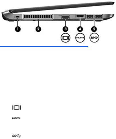
Left
Component |
|
Description |
|
|
|
(1) |
Security cable slot |
Attaches an optional security cable to the computer. |
|
|
NOTE: The security cable is designed to act as a |
|
|
deterrent, but it may not prevent the computer from being |
|
|
mishandled or stolen. |
|
|
|
(2) |
Vent |
Enables airflow to cool internal components. |
|
|
NOTE: The computer fan starts up automatically to cool |
|
|
internal components and prevent overheating. It is normal for |
|
|
the internal fan to cycle on and off during routine operation. |
|
|
|
(3) |
External monitor port |
Connects an external VGA monitor or projector. |
|
|
|
(4) |
HDMI port |
Connects an optional video or audio device, such as a high- |
|
|
definition television, or any compatible digital or audio |
|
|
component. |
|
|
|
(5) |
USB 3.0 ports (2) |
Connect optional USB 3.0 devices and provide enhanced |
|
|
USB power performance. |
|
|
|
14 |
Chapter 2 External component identification |
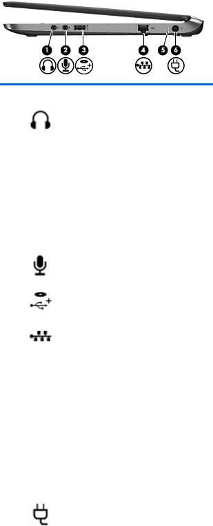
Right
Component |
|
Description |
|
|
|
(1) |
Audio-out (headphone) jack |
Produces sound when connected to optional powered stereo |
|
|
speakers, headphones, earbuds, a headset, or television |
|
|
audio. |
|
|
WARNING! To reduce the risk of personal injury, adjust |
|
|
the volume before putting on headphones, earbuds, or a |
|
|
headset. For additional safety information, see the |
|
|
Regulatory, Safety, and Environmental Notices. To access |
|
|
the user guides in Windows 8, select the HP Support |
|
|
Assistant app on the Start screen, select My computer, |
|
|
and then select User guides. |
|
|
NOTE: When a device is connected to the jack, the |
|
|
computer speakers are disabled. |
|
|
|
(2) |
Audio-in (microphone) jack |
Connects an optional computer headset microphone, stereo |
|
|
array microphone, or monaural microphone. |
|
|
|
(3) |
USB 2.0 + powered port |
Connect optional USB 2.0 devices and provide enhanced |
|
|
USB power performance. |
|
|
|
(4) |
RJ-45 (network) jack |
Connects a network cable. |
|
RJ-45 (network) lights (2) |
● Green (right): The network is connected. |
|
|
● Amber (left): The network is showing activity. |
|
|
|
(5) |
AC adapter/Battery light |
● White: The computer is connected to external power |
|
|
and the battery is charged from 90 to 99 percent. |
|
|
● Amber: The computer is connected to external power |
|
|
and the battery is charged from 0 to 89 percent. |
|
|
● Blinking amber: A battery that is the only available |
|
|
power source has reached a low battery level. When |
|
|
the battery reaches a critical battery level, the battery |
|
|
light begins blinking rapidly. |
|
|
● Off: The battery is fully charged. |
|
|
|
(6) |
Power connector |
Connects an AC adapter. |
|
|
|
Right 15

Bottom
Component |
|
Description |
|
|
|
(1) |
Battery release latches (2) |
Releases the battery. |
|
|
|
(2) |
Battery bay |
Holds the battery. |
|
|
|
(3) |
Vent |
Enable airflow to cool internal components. |
|
|
NOTE: The computer fan starts up automatically to |
|
|
cool internal components and prevent overheating. It is |
|
|
normal for the internal fan to cycle on and off during |
|
|
routine operation. |
|
|
|
(4) |
Service door |
Provides access to the wireless LAN (WLAN) module |
|
|
slot, the WWAN module slot, the SIM slot, and the |
|
|
memory module slots. |
|
|
CAUTION: To prevent an unresponsive system, |
|
|
replace the wireless module only with a wireless |
|
|
module authorized for use in the computer by the |
|
|
governmental agency that regulates wireless devices in |
|
|
your country or region. If you replace the module and |
|
|
then receive a warning message, remove the module to |
|
|
restore computer functionality, and then contact support |
|
|
through HP Support Assistant. To access HP Support |
|
|
Assistant from the Start screen, select the HP Support |
|
|
Assistant app. |
|
|
|
(5) |
SIM slot (Windows 8 models only) |
Supports a wireless subscriber identity module (SIM). |
|
|
The SIM slot is located inside the service door. |
|
|
|
16 |
Chapter 2 External component identification |
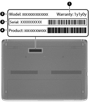
Service tag and PCID label
Service tag
When ordering parts or requesting information, provide the computer serial number and model description provided on the service tag.
●Warranty period (1). This number describes the duration (in years) of the warranty period for the computer.
●Model name (2). This is the product name affixed to the front of the computer.
●Serial number (s/n) (3). This is an alphanumeric identifier that is unique to each product.
●Part number/Product number (p/n) (4). This number provides specific information about the product's hardware components. The part number helps a service technician to determine what components and parts are needed.
Service tag and PCID label |
17 |
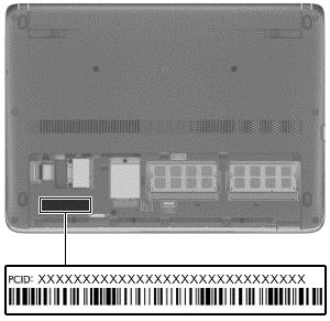
PCID label
The PCID label provides the information required to properly reset the notebook firmware (BIOS) back to factory shipped specifications when replacing the system board. The label may have a different number of characters depending on the operating system on the computer.
18 |
Chapter 2 External component identification |
3 Illustrated parts catalog
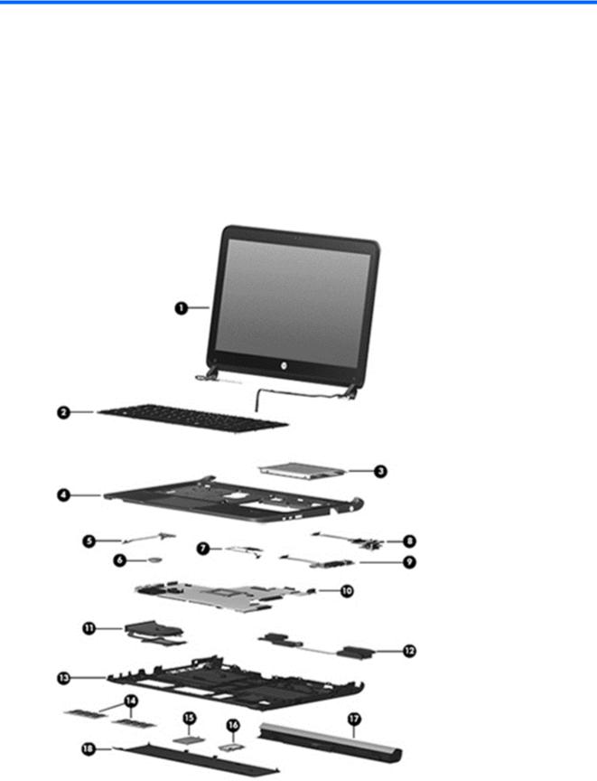
Computer major components
Computer major components |
19 |

Item |
Description |
Spare part |
|
|
|
|
number |
|
|
|
|
(1) |
Display panel, 33.8-cm (13.3-inch) HD, anti-glare |
|
|
|
|
|
|
|
For use in models without WWAN |
727758-001 |
|
|
|
|
|
|
For use in models with WWAN |
731997-001 |
|
|
|
|
|
(2) |
Keyboard (includes cable) |
727765-xxx |
|
|
NOTE: For a detailed list of available keyboards, see Sequential part number listing |
|
|
|
on page 26. |
|
|
|
|
|
|
(3) |
Hard drive |
|
|
|
|
|
|
|
500-GB, 5400-rpm |
683802-001 |
|
|
|
|
|
|
500-GB, 7200-rpm |
703267-001 |
|
|
|
|
|
|
128-GB solid-state drive |
737584-001 |
|
|
|
|
|
|
120-GB solid-state drive (M.2) |
731998-001 |
|
|
|
|
|
(4) |
Top cover (includes touchpad) |
|
|
|
|
|
|
|
For use in models with a fingerprint reader |
727753-001 |
|
|
|
|
|
|
For use in models without a fingerprint reader |
727754-001 |
|
|
|
|
|
(5) |
Power button board (includes cable) |
727760-001 |
|
|
|
|
|
(6) |
RTC battery |
684248-001 |
|
|
|
|
|
(7) |
Fingerprint reader assembly (includes bracket, grommet, and screw) |
727764-001 |
|
|
|
|
|
(8) |
Function board |
727768-001 |
|
|
|
|
|
(9) |
Audio board |
727759-001 |
|
|
|
|
|
(10) |
System board (includes replacement thermal material) |
|
|
|
|
|
|
|
For use in models with Intel Core i7-4500U processors: |
|
|
|
|
|
|
|
● |
Non-Windows 8 models |
727772-001 |
|
|
|
|
|
● Windows 8 Standard models |
727772-501 |
|
|
|
|
|
|
● Windows 8 Professional models |
727772-601 |
|
|
|
|
|
|
For use in models with Intel Core i5-4250U processors: |
|
|
|
|
|
|
|
● |
Non-Windows 8 models |
727771-001 |
|
|
|
|
|
● Windows 8 Standard models |
727771-501 |
|
|
|
|
|
|
● Windows 8 Professional models |
727771-601 |
|
|
|
|
|
|
For use in models with Intel Core i5-4200U processors: |
|
|
|
|
|
|
|
● |
Non-Windows 8 models |
727770-001 |
|
|
|
|
|
● Windows 8 Standard models |
727770-501 |
|
|
|
|
|
|
● Windows 8 Professional models |
727770-601 |
|
|
|
|
|
20 |
Chapter 3 Illustrated parts catalog |
Loading...