

Page 1

HP Designjet Z6100 Printer series
Service manual
Page 2

For HP Internal Use Only
©Copyright Hewlett-Packard
Company 2008
This document contains
proprietary information that is
protected by copyright. All
rights are reserved. No part of
this document may be
photocopied, reproduced, or
translated to another language
without the prior written
consent of Hewlett-Packard
Company.
First Edition, March 2007
Second edtion, May 2008
Warranty
The information contained in
this document is subject to
change without notice.
Hewlett-Packard makes
no warranty of any kind
with regard to this
material, including, but
not limited to, the implied
warranties of
merchantability and
fitness for a particular
purpose.
Hewlett-Packard shall not be
liable for errors contained
herein or for incidental or
consequential damages in
connection with the furnishing,
performance, or use of this
material.
WARNING
The procedures described in
this manual are to be
performed by HP-qualified
service personnel only.
Electrical Shock Hazard
Serious shock hazard leading
to death or injury may result if
you do not take the following
precautions:
- Ensure that the ac power
outlet (mains) has a protective
earth (ground) terminal.
- Disconnect the Printer from the
power source prior to
performing any maintenance.
- Prevent water or any other
liquids from running onto
electrical components or
circuits, or through openings in
the enclosure.
Electrostatic Discharge
Refer to the beginning of
Chapter 4of this manual, for
precautions you should take to
prevent damage to the Printer
circuits from electrostatic
discharge.
WARN ING
The Warning symbol calls
attention to a procedure,
practice, or the like, which, if
not correctly performed or
adhered to, could result in
personal injury. Do not
proceed beyond a Warning
symbol until the indicated
conditions are fully understood
and met.
CAUTION
The Caution symbol calls
attention to an operating
procedure, practice, or the like,
which, if not correctly
performed or adhered to, could
result in damage to or
destruction of part or all of the
product. Do not proceed
beyond a Caution symbol until
the indicated conditions are
fully understood and met.
Customer Assurance
Customer Experience Section
Large Format Printing Division
Hewlett-Packard Espanola, S.A.
Avda. Graells, 501
08190 Sant Cugat del Valles
Spain
Safety Symbols
General definitions of safety
symbols are given immediately
after the table of contents.
Page 3
HP Designjet Z6100 Printer series
Service manual
Page 4

Using this Manual
Purpose
This Service Manual contains information necessary to test, calibrate and service:
• HP Designjet Z6100 42-inch Printer (Model Q6651A)
• HP Designjet Z6100 60-inch Printer (Model Q6652A)
For information about using these printers, refer to the corresponding User and Quick Reference Guides.
Readership
The procedures described in this Service Manual are to be performed by HP Certified service personnel
only.
Part Numbers
Part Numbers for Printer options, accessories and service parts are located in Chapter 7.
Conventions
A small arrow ⇒ is used to indicate other parts of the Service Manual where you can find information
related to the topic you are consulting.
Page 5

1Table of Contents
1 Troubleshooting
Troubleshooting the printer......................................................................................................... 2
Printer Education and Training..................................................................................... 2
Firmware upgrade ..................................................................................................... 2
Troubleshooting system error codes............................................................................................. 2
Performing a service test on a failed assembly.............................................................................. 2
Performing the necessary service calibrations ............................................................................... 3
Solving print quality problems .................................................................................................... 3
The printer does not power on.................................................................................................... 3
Printer hangs during printing and displays ‘processing’ ................................................................. 3
The printer continuously rejects printheads ................................................................................... 4
A new Maintenenace Cartridge is incorrectly detected as ‘used’ .................................................... 4
Cover sensors are not working ................................................................................................... 4
The line sensor has problems detecting media .............................................................................. 5
Troubleshooting Media Jams/Printhead Crashes........................................................................... 5
Troubleshooting shutdowns ........................................................................................................ 5
Printhead Maintenance Cartridge Path ......................................................................... 6
Paper Path ................................................................................................................ 6
Printhead path ........................................................................................................... 6
PWM shutdown ......................................................................................................... 6
Velocity shutdown ...................................................................................................... 6
Energy shutdown ....................................................................................................... 6
Vacuum suction much lower at high altitudes................................................................................ 7
Banding at variable extreme environmental conditions .................................................................. 7
Printhead Crashes/Smears on High Density Prints Using Coated Media .......................................... 7
Banding due to ink cartridge replacement while printing ............................................................... 7
34" Rice Paper not supported .................................................................................................... 8
Worm marks on HP Coated media with light area fills .................................................................. 8
Solving Media-Handling Problems .............................................................................................. 8
Difficult to load media “Too much skew” ..................................................................................... 8
Troublshooting a failure with the Take UP Reel (TUR) ..................................................................... 9
Take Up Reel LED status information ............................................................................. 9
Checking the Take Up Reel is correctly installed ........................................................... 10
How the Take UP Reel Works .................................................................................... 11
Using the buzzer at power-up for troubleshooting problems........................................... 11
Using the Power-up Sequence to Troubleshoot ............................................................. 12
Corrective Actions for Power-Up Problems ................................................................... 14
Troubleshooting OMAS problem .............................................................................................. 14
Using the Power Switch LEDs to Troubleshoot ............................................................................. 15
Using the PCA LEDs to Troubleshoot.......................................................................................... 16
Interconnect PCA ..................................................................................................... 16
PrintMech PCA ........................................................................................................ 17
Identifying faults from LED status ................................................................................ 17
How to Interpret the Service Information Pages ........................................................................... 19
Main Characteristics ................................................................................................ 20
Current Configuration............................................................................................... 21
Current Media, Printhead and Ink Information ............................................................. 22
v
Page 6

Printer Usage Information.......................................................................................... 23
Media Used Sections................................................................................................ 24
Event Logs............................................................................................................... 25
Calibrations Status ................................................................................................... 26
Connectivity Configuration........................................................................................ 28
When the main window is open and the printer is printing (safety compliance) .............................. 29
General RIP tips and tricks ....................................................................................................... 29
Frequently Asked Questions ...................................................................................... 30
How to troubleshoot the 79:04 System Error .............................................................................. 31
Introduction............................................................................................................. 31
Possible causes........................................................................................................ 32
Troubleshooting based on symptoms .......................................................................... 38
2 System Error Codes
Introduction............................................................................................................................ 44
System Error Codes and Warnings - Explanation........................................................................ 44
Continuable and Non-Continuable Error Codes.......................................................................... 47
3 Ink Supplies
What are Ink Supplies? ........................................................................................................... 80
Ink Cartridges.......................................................................................................... 80
Printheads............................................................................................................... 81
Maintenance Cartridge............................................................................................. 82
General Information About the Ink Supplies ............................................................................... 82
General Precautions When Handling Ink Supplies ...................................................................... 82
Priming the Ink System............................................................................................................. 83
When Should You Replace the Ink Supplies?.............................................................................. 83
Obtaining Ink Cartridge Information ......................................................................................... 83
Obtaining Printhead Information............................................................................................... 85
Ink Cartridge Status Messages................................................................................... 86
Ink Cartridge Status While Printing............................................................................. 86
Ink Cartridge Status While Replacing ......................................................................... 86
Printhead Status Messages While Printing ................................................................... 87
Printhead Status Messages While Replacing................................................................ 87
Maintenance Cartridge Status Messages While Printing ............................................... 88
Maintenance Cartridge Status Messages While Replacing ............................................ 88
Summary of Solving Ink Supplies Problems................................................................................. 88
Problems reseating the printhead ............................................................................... 88
You Cannot Insert the Ink Cartridge Into the Printer....................................................... 89
You Cannot Insert the Printhead Into the Printer ............................................................ 89
You Cannot Insert the Maintenance Cartridge Into the Printer ........................................ 89
Troubleshooting Printhead Error Codes...................................................................................... 90
Carriage Interconnect Wiper ................................................................................................... 91
Warranty Information for Ink Supplies ....................................................................................... 91
Ink Cartridge........................................................................................................... 91
Printheads............................................................................................................... 92
4 Service Tests and Utilities
Introduction............................................................................................................................ 94
Diagnostics - Self Test.............................................................................................................. 94
Phone Support........................................................................................................................ 94
Service Tests (Diagnostics) ....................................................................................................... 94
Entering the Service Tests Menu................................................................................................ 96
1. Scan Axis Test ..................................................................................................... 97
2. Paper Drive Test................................................................................................. 101
3. Electronics Module Test....................................................................................... 105
4. Carriage Assembly Test ...................................................................................... 112
5. Sensors Test ...................................................................................................... 112
6. Ink Delivery System Test ...................................................................................... 115
7. SVS Test ........................................................................................................... 116
8. Air Pump System Test ......................................................................................... 116
9. Vacuum Fans Test .............................................................................................. 117
vi
Page 7

10. OMAS Module Test.......................................................................................... 118
11 EEROM Reset ................................................................................................... 118
12. Color Sensor Test ............................................................................................. 119
13. Aerosol Test .................................................................................................... 122
14. Primer Test ...................................................................................................... 122
15.1 Service Special Utilities >>> Bag Broken Recovery............................................. 124
15.2 Service Special Utilities >>> Error 71:19 Recovery ............................................ 126
15.3 Service Special Utilities >>> IO Information ...................................................... 128
15.4 Service Special Utilities >>> Unit Information .................................................... 128
15.5 Service Special Utilities >>> Check Ink Supplies ................................................ 129
Emergency Firmware Upgrade ................................................................................ 130
Service Utilities..................................................................................................................... 132
Entering the Service Utilities Menu............................................................................ 133
1. Turn Drive Roller ................................................................................................ 134
2. Prime Tubes....................................................................................................... 135
3. Set SN.............................................................................................................. 138
4. Reset Life Counters ............................................................................................. 138
5. Diagnostic Print ................................................................................................. 140
6. Sleep Mode ...................................................................................................... 141
7. Replace Cutter ................................................................................................... 142
8. Set RTC Clock.................................................................................................... 142
9. Enable/Disable Firewall ..................................................................................... 143
10. Prime Printhead X............................................................................................. 144
11. Open/Close SOL............................................................................................. 145
12. Disk Wipe DoD 5330.22’M ............................................................................. 145
13. Enable/Disable SCAPA .................................................................................... 148
14. Spectrophotometer test (Colormeter test).............................................................. 148
5Service Calibrations
Service Calibrations.............................................................................................................. 152
Entering the Service Calibrations Menu ................................................................................... 153
1. Scan Axis Calibration......................................................................................... 154
2. Paper Advance Calibration ................................................................................. 157
3. Drop Detector Calibration ................................................................................... 162
4. Line Sensor Calibration....................................................................................... 163
5. Vacuum Calibration ........................................................................................... 166
6. OMAS Calibration............................................................................................. 167
7. Primer Calibration.............................................................................................. 173
8. Platen Blue Line Calibration................................................................................. 177
6 Print Quality
How to Use the Image Quality Service Diagnostic Print ............................................................. 181
What is the Image Quality Service Diagnostic Print? .................................................. 181
Considerations for Printing the Diagnostic Print .......................................................... 182
Printing the Image Quality Service Print .................................................................... 182
Diagnostic Part 1: Printhead Problems ...................................................................... 183
Diagnostic Part 2: Alignment Test............................................................................. 184
Diagnostic Part 3: Printheads & Paper Advance Test................................................... 185
No Printing Defects Found in the Diagnostic Print ....................................................... 186
Visual Alignment Diagnostic Print ............................................................................. 187
Plot for escalation only............................................................................................ 190
Force Drop Detection.............................................................................................. 192
Disable Paper Advance Sensor ................................................................................ 192
Fix paper advance issues........................................................................................ 192
Clean the paper advance sensor window ................................................................. 194
The User Advance Calibration. ................................................................................ 194
Visual Paper Advance Plot ...................................................................................... 195
Interpreting plot results............................................................................................ 196
Image quality issues by symptom ............................................................................................ 199
There is banding in the image ................................................................................. 199
Lines are too thick, too thin, or missing ..................................................................... 200
vii
Page 8

Lines appear stepped or jagged .............................................................................. 200
Parts of lines or text are missing ............................................................................... 201
Lines are blurred (ink bleeds from lines) .................................................................... 202
Lines are slightly warped ........................................................................................ 202
Dark or light horizontal lines across the image (banding)............................................ 202
The image is grainy. .............................................................................................. 203
The image has a metallic hue (bronzing)................................................................... 204
The printed output is not flat .................................................................................... 204
The print smudges when touched ............................................................................. 205
Defects near the top of a print ................................................................................. 205
There are ink marks on the paper ............................................................................ 205
Colors are inaccurate ............................................................................................. 206
Colors between different HP Designjets do not match ................................................. 207
The output is completely blank ................................................................................. 209
The output contains only a partial print ..................................................................... 209
The image is clipped .............................................................................................. 209
The image is in one portion of the printing area......................................................... 210
The image is unexpectedly rotated ........................................................................... 210
The print is a mirror image of the original ................................................................. 210
The print is distorted or unintelligible ........................................................................ 210
One image overlays another on the same print.......................................................... 210
Pen settings seem to have no effect .......................................................................... 210
The image has a wood-grain appearance (aeroworms) .............................................. 210
CAD Lines look misaligned, images are blurred ......................................................... 211
Some media might deform when printing high area fill ............................................... 211
Printheads fail repeatedly........................................................................................ 211
Working with other commercially available media ................................................................... 213
7 Parts and Diagrams
Printer Support ..................................................................................................................... 222
Center Covers ...................................................................................................................... 224
Electronics Module................................................................................................................ 226
Right Cover.......................................................................................................................... 228
Left Cover ........................................................................................................................... 230
Right Hand Assemblies.......................................................................................................... 232
Left Hand Assemblies ............................................................................................................ 234
Carriage Assembly ............................................................................................................... 236
Scan-Axis Assemblies............................................................................................................ 238
Drive Roller and Media-Axis Motor ......................................................................................... 240
Paper Path Assemblies .......................................................................................................... 242
Center Guide and Pinchwheel Assembly.................................................................................. 244
Media Entry Assemblies ........................................................................................................ 246
Take-Up Reel Assembly.......................................................................................................... 248
Miscellaneous Parts............................................................................................................... 250
8 Removal & Installation
Service Part Order ................................................................................................................ 253
Disassembly Order ............................................................................................................... 255
Introduction.......................................................................................................................... 257
Safety Precautions.................................................................................................. 257
Electrostatic Discharge (ESD) Precautions .................................................................. 257
Required Tools....................................................................................................... 257
Screw Types ........................................................................................................................ 259
Window (42-inch) ................................................................................................................ 260
Installation of New Window ................................................................................... 261
Window (60-inch) ................................................................................................................ 262
Right Cover.......................................................................................................................... 264
Right Trim ............................................................................................................................ 267
Left Cover ............................................................................................................................ 270
Left Trim............................................................................................................................... 272
Top Cover (42-inch) .............................................................................................................. 273
viii
Page 9

Top Cover (60-inch) .............................................................................................................. 277
Rear Door (42-inch) .............................................................................................................. 281
Rear Door (60-inch) .............................................................................................................. 283
Right Connector Cover .......................................................................................................... 285
Left Connector Cover (42-inch) ............................................................................................... 287
Electronics Module Extension (60-inch only) ............................................................................. 288
Window Position Sensor........................................................................................................ 289
Front Panel........................................................................................................................... 292
Primer Assembly ................................................................................................................... 294
Primer Valves ....................................................................................................................... 296
Service Station ..................................................................................................................... 300
Vacuum Fan......................................................................................................................... 304
Aerosol Fan and Filter ........................................................................................................... 307
Drop Detector....................................................................................................................... 309
Ink Supply Tubes and Trailing Cable ....................................................................................... 312
ISS to Cartridge Cables ......................................................................................................... 318
Cutter Assembly.................................................................................................................... 319
Ink Supply Station (ISS).......................................................................................................... 321
APS Assembly ...................................................................................................................... 324
Left Spittoon ......................................................................................................................... 328
Encoder Strip and Encoder Sensor .......................................................................................... 331
Carriage PCA ...................................................................................................................... 334
Carriage Flex Cables ............................................................................................................ 337
Carriage Assembly ............................................................................................................... 339
Belt Assembly....................................................................................................................... 345
Scan-Axis Motor ................................................................................................................... 346
Media-Axis Motor................................................................................................................. 349
Optical Media Advance Sensor (OMAS) ................................................................................. 351
Interconnect PCA .................................................................................................................. 357
EIO to PCA Interface Card..................................................................................................... 360
OMAS Controller Card ......................................................................................................... 362
OMAS Cable....................................................................................................................... 364
Sausalito PCI PCA ................................................................................................................ 369
CPU Fan.............................................................................................................................. 371
Memory Module................................................................................................................... 373
Main PCA Formatter ............................................................................................................. 375
Hard Disk Drive (HDD) .......................................................................................................... 377
Power Supply Unit (PSU)........................................................................................................ 379
PrintMech PCA ..................................................................................................................... 384
Formatter Battery .................................................................................................................. 386
Electronics Module................................................................................................................ 388
Line Sensor Assembly ............................................................................................................ 390
Color Sensor Assembly.......................................................................................................... 392
Color Sensor Actuator Assembly ............................................................................................. 395
Media Deflector ................................................................................................................... 397
Output Platen ....................................................................................................................... 398
Center Platen ....................................................................................................................... 400
Cartridge Tray...................................................................................................................... 409
Input Roller .......................................................................................................................... 411
Maintenance Cartridge Door ................................................................................................. 413
Maintenance Cartridge Door Sensor ....................................................................................... 414
Media Sensor ...................................................................................................................... 415
Encoder Disc and Sensor ....................................................................................................... 417
Media Lever Assembly .......................................................................................................... 420
Media Lever Sensor .............................................................................................................. 423
Pinchwheel Assembly ............................................................................................................ 425
Center Guide ...................................................................................................................
Roller .......................................................................................................................... 433
Drive
Right Rollfeed Module Assembly ............................................................................................. 439
.... 430
ix
Page 10

Left Rollfeed Module Assembly ............................................................................................... 440
Take-Up Reel Motor .............................................................................................................. 442
Take-Up Reel Left Hand Module.............................................................................................. 444
Take-Up Reel Deflector Supports ............................................................................................. 445
Take-Up Reel Sensors ............................................................................................................ 447
9 Preventive Maintenance
Preventive Maintenance......................................................................................................... 452
Moisture on the Printer............................................................................................ 452
Noisy Carriage Bushing ......................................................................................... 452
Belt Swelling ......................................................................................................... 452
Cleaning the Printer ............................................................................................... 452
General Cleaning .................................................................................................. 452
Cleaning the Drive Roller and Overdrive................................................................... 452
Cleaning the Platen ................................................................................................ 453
Clean the Encoder Strip .......................................................................................... 454
Clean the paper-advance sensor window.................................................................. 457
Applying Oil to the Overdrive ................................................................................. 458
Lubricating the Carriage Assembly........................................................................... 458
Change the maintenance absorber .......................................................................... 459
Scheduled Maintenance ......................................................................................... 460
Level of Printer Usage ............................................................................................. 460
x
Page 11

1 Troubleshooting
• Troubleshooting the printer ..................................................................................... 2
• Printer Education and Training.......................................................................... 2
• Firmware upgrade .......................................................................................... 2
• Troubleshooting system error codes.......................................................................... 2
• Performing a service test on a failed assembly........................................................... 2
• Performing the necessary service calibrations............................................................ 3
• Solving print quality problems................................................................................. 3
• The printer does not power on ................................................................................ 3
• Printer hangs during printing and displays ‘processing’ .............................................. 3
• The printer continuously rejects printheads ................................................................ 4
• A new Maintenenace Cartridge is incorrectly detected as ‘used’.................................. 4
• Cover sensors are not working ................................................................................ 4
• The line sensor has problems detecting media........................................................... 5
• Troubleshooting Media Jams/Printhead Crashes ....................................................... 5
• Troubleshooting shutdowns ..................................................................................... 5
• Vacuum suction much lower at high altitudes............................................................. 7
• Banding at variable extreme environmental conditions ............................................... 7
• Printhead Crashes/Smears on High Density Prints Using Coated Media ....................... 7
• Banding due to ink cartridge replacement while printing............................................ 7
• 34" Rice Paper not supported ................................................................................. 8
• Worm marks on HP Coated media with light area fills ............................................... 8
• Solving Media-Handling Problems........................................................................... 8
• Difficult to load media “Too much skew”................................................................... 8
• Troublshooting a failure with the Take UP Reel (TUR) .................................................. 9
• Using the buzzer at power-up for troubleshooting problems ....................................... 11
• Using the Power-up Sequence to Troubleshoot .......................................................... 12
• Troubleshooting OMAS problem ............................................................................ 14
• Using the Power Switch LEDs to Troubleshoot............................................................ 15
• Using the PCA LEDs to Troubleshoot........................................................................ 16
• How to Interpret the Service Information Pages .........................................................19
• When the main window is open and the printer is printing (safety compliance)........... 29
• General RIP tips and tricks.................................................................................... 29
• How to troubleshoot the 79:04 System Error ............................................................ 31
Troubleshooting
1
Page 12

Troubleshooting the printer
Refer to Section 6 for troubleshooting Image Qulaity issues.
Printer Education and Training
Before any attempt is made to troubleshoot the printer, it is critical that you have the relevant training on
Troubleshooting
the HP Designjet Z6100 Printer series. If you are not trained on this printer, please contact HP Education
or HP Training to enquire about becoming ‘HP Service Qualified’ for this printer.
Firmware upgrade
The first step to take when trying to clear an errror with the printer is to check that the firmware installed
in the printer is the latest available. Firmware updates often include fixes for some of the problems that
are found in the following pages, simply updating the firmware can often resolve the problem. New
firmware can be downloaded from the following url: http:www.hp.com/go/designjet/downloads
If the error with the printer does not allow you to upgrade the firmware using the normal process, try
upgrading the firmware using the emergency .plt file procedure
Troubleshooting system error codes
Chapter 2, System Error Codes contains a list of system error codes and their respective descriptions and
recommended corrective actions. Only try one recommended action at a time and check if the error code
has disappeared.
⇒ page 130
If you have an error code which is not documented in this Service Manual or you have an error which
you cannot resolve, then report the error to the HP Response Center or the nearest HP Support Office.
When reporting the error, have the following information ready:
• Model and Serial Number of the printer.
• Which firmware revision the printer is using (See Note below). Check firmware in Utilities / Statistics
/ Code rev.
• The complete error number.
NOTE: When reporting the System Error Code, make sure that you supply the full Error Code
and the firmware version. Without this information, HP Support Personnel cannot help you.
• The Service Configuration Print.
• The Current configuration sheet.
• Which software application the customer is using (name, version, etc.).
Performing a service test on a failed assembly
If possible, always perform a Service Test on the component/assembly that you are about to replace, just
to make sure that is the component/assembly that has failed.
NOTE: If the test on that component/assembly passes, you should NOT replace it.
For information on the Service Tests and how to use them see Chapter 4, Service Tests and Utilities.
2 Chapter 1 Troubleshooting
Page 13

Performing the necessary service calibrations
Is the printer calibrated correctly after replacing a component? For information on the Service Calibrations
and how to use them see Chapter 5, Service Calibrations.
NOTE: Remember that certain Calibrations are required even if an Assembly has been
disassembled to gain access to another Assembly or Component.
Solving print quality problems
Whenever a Print Quality problem appears, it is advisable to print the Diagnostic Print to help diagnose
the problem. The Diagnostic Print will help you differentiate between possible printhead errors and other
problems such as incorrect front-panel selection, driver or RIP configuration or mechanical problems. For
information on solving Print Quality problems see Chapter 6, Print Quality.
The printer does not power on
To resolve printer power up problems, do the following:
1. Check that the power cord is connected correctly to the Printer and to the Power Socket.
2. Check that the Power Switch on the BACK of the Printer is in the ON position.
Troubleshooting
3. Check to see if any of the LEDs on the Power Switch are On. If any of the LEDs are On, then refer to
See page 15 for more information.
4. Check that the Front-Panel Cable is correctly connected to the Electronics Module. Also make sure
that the Front-Panel cable is not damaged.
5. Replace the CPU Fan
6. Replace the Power Supply Unit
⇒ See page 371
⇒ See page 379.
Printer hangs during printing and displays ‘processing’
It has been seen under certain circumstances that the printer hangs whilst printing, this may happen
immediately after printing, or only a partial print. In some cases when this occurs if the machine is
rebooted a system error 79:04 is displayed, although rebooting again appears to clear this error. After
this point, although the printer displays that it is in the “Ready” state, attempting to print anymore plots
will once again hang the printer, including internal demo plots.
Reason
The reason for this error is that a large spooled file (11Gb for example) has been sent to the printer and
has been placed in the disk partition which is related to the print queue. The file completely fills up all the
disk space, because of this it will never successfully print, and so the file remains in the disk partition.
Even after restarting the printer the file remains, subsequent print requests also fail as there is not sufficient
space available in the partition to process anything else.
Solution
Perform the following few steps to clear the error.
Performing the necessary service calibrations 3
Page 14

1. Check that the firmware is the latest available (at least 7.0.03)
2. Turn Off and ON the printer.
3. Set Queue to OFF.
4. Set ‘When Start Printing’ to ‘Immediately’.
Please guide the customer through the front panel of the printer to set up the “Queue” to “OFF” and
Troubleshooting
“When Start Printing” to “Immediately”.
Wipe disk solution
If the above procedure does not clear the error, use the wipe the hard disk procedure (Unsecure mode)
⇒ See page 145. This will delete all previous jobs, ICC profile, media profiles that were present on the
hard disk. This procedure has an advantage for the customer in that it solves the issue without the need
to wait for an onsite engineer to come to their premises and remove and replace the HDD (which would
also have the same affect of deleting all the previous jobs, ICC profiles and media profiles). The whole
procedure should not take more than 30-35 minutes.
Important step is that you need to select the Unsecure mode
The printer continuously rejects printheads
To resolve printhead rejection problems, do the following:
1. Clean the flex contacts on the Printhead and in the Carriage Assembly using the Carriage Intercon-
nect Wiper (Refer to Chapter 3) and try again.
2. If ALL the Printheads are rejected (the status message on the Front Panel does NOT show “OK” for
ALL the Printheads) then perform the Electronic Systems Test
⇒ See page 105.
A new Maintenenace Cartridge is incorrectly detected as ‘used’
This can occur if the printer has detected the previous Maintenenace Cartridge was nearly full, and when
a new Maintenenace Cartridge is installed the Front Panel displays an error that the cartridge is ‘used’.
To resolve the problem, do the following:
1. Ensure the firmware installed in the printer is the latest available.
2. Once the latest firmware is installed repeat the Maintenance installation procedure with the same
cartridge.
3. Manuall reset the counter of the Maintenance Cartridge
⇒ See page 138
Cover sensors are not working
To resolve cover sensor problems, do the following:
1. Perform the Sensors Test
2. Check if the cable for the faulty sensor is not damaged and is connected correctly.
3. Replace the faulty Sensor.
4 Chapter 1 Troubleshooting
⇒ See page 112.
Page 15

The line sensor has problems detecting media
To resolve line sensor media detection problems, do the following:
1. Check the type of media that is being used since the Line sensor may have problems detecting trans-
parent media or some types of Non-HP media. Try loading white HP media in to the Printer and
check if the Line sensor detects it.
2. Excessive ink deposits on the Platen surface can fool the sensor by reflecting the light. Clean the
Center Platen.
3. Clean the Encoder Strip ⇒ See page 454.
4. The Line Sensor is not calibrated correctly. Perform the Line Sensor Calibration ⇒ See page 163.
5. The Line Sensor is damaged or faulty. Replace the Line Sensor ⇒ See page 390.
Troubleshooting Media Jams/Printhead Crashes
NOTE: If you are using HP Coated Media when the problem occurred, please also refer to
Page 1-6.
The failure modes “media jam” and “head crash” are grouped together because in many cases a media
jam causes the media to lift up into the Carriage path and cause a Printhead crash, thus causing many
media jam failures to be reported as head crashes.
Troubleshooting
1. Did the media jam occur when loading media?
NOTE: When clearing a media jam, sometimes media is stuck in the paper path. To clear
this, you must lift the Media Lever and insert thicker media into the paper path to push out the
media that is still stuck there.
• If the client has had media jams, it is common for pieces of media to get stuck in the media
path. Clear the media path.
2. Is the customer using non-HP media?
• The use of non-HP media can easily be the cause of media jams and head crashes (especially
head crashes because HP media is specially formulated to avoid cockle, one of the primary
causes of head crashes). If the media is not HP approved, advise the customer to use HP media
and check to see if the problem is now solved.
3. Check that the Vacuum Fan works correctly.
Troubleshooting shutdowns
If a shutdown occurs, you will get the message “Switch Power Off” followed by one of these messages:
• Check Maintenance Cartridge Path.
• Check Paper Path.
The line sensor has problems detecting media 5
Page 16

• Check Printhead Path.
NOTE: A shutdown in each path will require different steps to resolve the problem as
explained below. In each case, make sure that you power OFF the printer before attempting
any procedures to resolve the problem.
Printhead Maintenance Cartridge Path
Troubleshooting
Open the right door of the printer and check for any visible obstacles restricting the movement of the
Service Station. Manually move the Service Station, checking for smooth and free movement.
Paper Path
To resolve paper path problems, do the following:
1. Open the Window and check for any visible obstacles restricting the movement of the Drive Roller.
Make sure that the mylar is not damaged. If there is a wrinkled mass of media inside the paper
path, lift the Pinch wheels (using the Media Load Handles) and clear the obstruction.
2. If this shutdown happens at the end of a Roll of Media, it could be because the media is stuck firmly
to the Roll. Lift the Pinch wheels (using the Media Load Handles) and pull the media clear.
3. Replace media spindle if broken.
4. Replace the Media-Axis Motor
Printhead path
When a shutdown occurs in the Printhead path, you will get the message “Switch Power Off / Check
Printhead Path (*). The (*) will be a number, which will give an indication on where the failure occurred:
PWM shutdown
To resolve a PWM shutdown, do the following:
1. Clean Slider Rods and Apply Oil along the complete axis of the Slider Rods. After applying the Oil,
perform the Scan-Axis Test
2. Clean the Encoder Strip ⇒ See page 454.
3. Replace the Scan-Axis Motor
Velocity shutdown
To resolve a velocity shutdown, do the following:
1. Open the Window and check for any visible obstacles restricting the movement of the Carriage
Assembly. Try and move the Carriage Assembly manually, checking for smooth and free movement.
⇒ See page 349.
⇒ See page 97 and check that the values are within the given limits.
⇒ See page 346.
2. Check that the Encoder Strip is clean. If necessary, clean Encoder Strip using a damp cloth.
Energy shutdown
To resolve an energy shutdown, do the following:
1. Clean Slider Rods and Apply Oil along the complete axis of the Slide Rods. After applying the Oil,
perform the Scan-Axis Test
2. Clean the Encoder Strip ⇒ See page 454.
6 Chapter 1 Troubleshooting
⇒ See page 97 and check that the values are within the given limits.
Page 17

3. Replace the Scan-Axis Motor ⇒ See page 346.
Vacuum suction much lower at high altitudes
At altitudes above 3,000 meters, the vacuum force holding down the media will be lower, therefore the
media will not be held in place properly causing:
• Ink Smearing on the Media.
• Printhead crashes against the Media.
• Roll Media loading problems (low probability).
PRINTER LIMITATION - NO SOLUTION AVAILABLE.
Banding at variable extreme environmental conditions
NOTE: This problem is only applicable if the OMAS is disabled.
Since the Accuracy Calibration has been done at normal environmental conditions, printing in extreme
environmental conditions will cause banding because the advance of the Drive Roller does not correspond
to the same conditions that the calibration was done in. To solve the problem, try the following:
Perform the Accuracy Calibration in the new environmental conditions (Refer to the User’s Guide).
Printhead Crashes/Smears on High Density Prints
Troubleshooting
Using Coated Media
High density prints can cause cockle mainly on HP Coated Media. This causes two main problems:
1. Cockling in the borders - Because the printer places too much ink on the Coated Media, the borders
of the print become raised, causing the Printhead to crash against the media. To solve the problem,
try the following:
• Change the paper margins to 15mm, either in the Front Panel or in the Driver. If the customer is
printing PostScript images, send them a PPD file containing the extended margins of 15mm.
2. Cockling within the print - If the Printer places too much ink within the print, the media starts to rip-
ple, causing the Printhead to smear against the media. To solve the problem, try the following:
• Check in the Front Panel if Ink Limiting is ON or OFF. If Ink Limiting is OFF, turn it ON.
• Never use HP Coated Media for High Density prints. As a substitute use HP Heavy Coated
Media.
Banding due to ink cartridge replacement while printing
A user has removed the Ink Cartridge while the printer was printing, which has caused the printer to stop.
If the user does not replace the Ink Cartridge immediately, when the printer starts to print again, a band
will appear in the position where the printing restarted. This is because the wet ink interacts with the dried
ink on the media causing the band to appear. To solve the problem, try the following:
Vacuum suction much lower at high altitudes 7
Page 18

• Do NOT remove the Ink Cartridge while the Printer is Printing. Only replace/remove Ink Cartridges
in between Prints.
• If the Ink Cartridge was replaced due to the “Empty” status on the Front Panel, then advise the
customer to replace the Ink Cartridge when the “Very Low” status is showing on the Front Panel.
• Reprint the file (without remove the Ink Cartridge).
Troubleshooting
34" Rice Paper not supported
Roll length is 34" (Non-standard) and the pinch wheels can't control edge of media causing ink smears
and Printhead crashes in middle of prints with or without area fills.
PRINTER LIMITATION - NO SOLUTION AVAILABLE.
Worm marks on HP Coated media with light area fills
Light bands (S-shaped) in Paper axis direction where light area fills are printed, causing unacceptable
Image Quality defect.
• Print the Service Configuration Print and check if the level of Humidity is very low (below 30%).
Increasing humidity may help in reducing the severity of the problem.
NOTE: The media is causing the problem and NOT the Printer. Do not attempt to try and
replace Printer parts to solve this problem.
Solving Media-Handling Problems
The Front Panel Keeps Indicating that Media Is Misaligned or Incorrectly Positioned.
• The roll may be loaded the wrong way. The paper should load over the roll toward you.
• Check that the paper is correctly loaded onto the spindle.
• The paper may be loaded at an angle. The right-hand edge must be aligned with the blue line on
the Print Platen.
NOTE: Ensure that the paper is wrapped tightly on the roll. This is a very important step to
remember because if this is not done, the media may be loaded at an angle, causing the
media to be rejected.
Difficult to load media “Too much skew”
If you encounter a high failure rate when loading media and the Front Panel reports “Too Much Skew” it
is likely that:
• The encoder strip must be cleaned (this can be carried out by the customer using the User
Maintenance Kit).
• The Line Sensor must be cleaned.
• The Blue Line calibration must be performed (see “8. Platen Blue Line Calibration” on page 177).
8 Chapter 1 Troubleshooting
Page 19

Troublshooting a failure with the Take UP Reel (TUR)
Use this section to troubleshoot failures with the TakeUP Reel.
Take Up Reel LED status information
LED
status
Blinking
quickly
Blinking
slowly
Solid red Take Up Reel
Solid green Take Up Reel
Solid green Take Up Reel
Issue Print job
Take Up Reel
not winding
Take Up Reel
not winding
not winding
not winding
winding in the
wrong direction, and not
stoppinjg the
job.
Possible cause Print job
interupted
Yes Sensor beam blocked for
more than 3 seconds
No The sensor cables are
loose or unplugged
No There is too much resis-
tance on the Take Up Reel
motor
No The Take Up Reel power
switch is in the Off position
No The Take Up Reel wind
direction switch is in the
wrong winding position.
after 3 seconds, the
printer will recognize the
problem and interupt the
print job. In this case, see
the first error listed in this
table.
Troubleshooting
interrupted?
Ensure the Take Up Reel sensors
are not blocked by a strip of
paper, the collection bin or other
objects.
Also ensure the Take Up Reel
power switch is in the On position.
Ensure the sensor cables are correctly connected.
ENSURE THAT THE TUR Spindle
Lever is CLOSED! Ensure the
paper is not winding too tightly.
A loop-shaping core should be
inserted and hanging down.
Ensure the Take Up Reel power
switch is in the On position.
Flip the Take Up Reel wind-direction switch to the correct position.
NOTE: If the LED is flashing but there is no message on the front panel, restart the printer.
Troublshooting a failure with the Take UP Reel (TUR) 9
Page 20
Checking the Take Up Reel is correctly installed
Many system error codes are displayed as a result of the Take UP Reel not being installed correctly or
because parts have moved or become dislodged from their correct positions. This troubleshooting
procedure checks the machnical installation of the Take Up Reel.
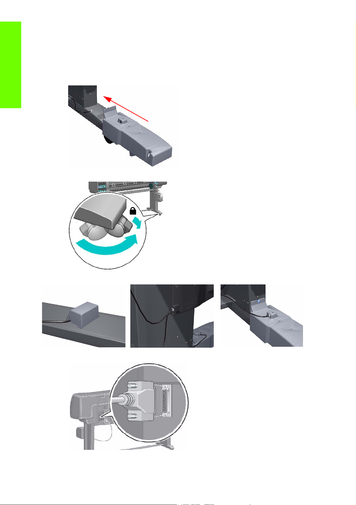
1. Check that the Take UP Reel sensor unit is correctly installed on the right foot.
Troubleshooting
2. To correctly install the foot, the wheel has to be positioned as shown.
3. Check the cables linking the sensors to the Take Up Reel Motor Assembly are correctly connected.
4. Check that the Take UP Reel motor assembly is correctly connected to the rear of the printer.
10 Chapter 1 Troubleshooting
Page 21

How the Take UP Reel Works
There are two different setups:
1. The Take Up Reel has been installed via the front panel from the media menu – how to check it: If the
words 'Take Up Reel installed' is blanked out, this means that the Take Up Reel is not installed in the
front panel.
2. The Take UP Reel has not been install via the front panel – how to check it: When selecting the
media menu, there is no line ‘Take Up Reel installed’. This does not mean that the Take Up Reel will
not work, it just means that if there is a paper jam detected by the Take Up Reel, there will be no
warning system error displayed on the front panel. The printer will not stop.
How to install the Take Up Reel:
From the Media menu -> Take Up Reel -> Enable Take Up Reel. The main differences between the two
modes (Take Up Reel installed or not installed on the front panel), what will happen if the Take Up Reel
is installed:
• In case of Take Up Reel Paper jam system error, a warning is reported on the front panel, and the
printer is no more printing (pause)
• The cutter is disabled between jobs
• When unloading the media, the front panel will ask you to manually cut the media.
How it works?
When the bottom of the 'loop shaper' is lower enough and it cuts the signal between the 2 sensors, the
Take Up Reel starts to move the motor until the signal between the 2 sensors is passing through again.
If after the few seconds of turning the Take Up Reel, the signal between two sensors is still cut, the Take
Up Reel reports a 'Take Up Reel paper jam' error:
• In all case, the LED of the Take Up Reel is blinking quickly
Troubleshooting
• and if the Take Up Reel is enabled on the front panel, a 'Take Up Reel' paper jam will be displayed.
Using the buzzer at power-up for troubleshooting problems
When the Printer is powered up, it doesn’t make a “Beeping Sound” until it is completely powered-up and
ready to use. If there is a beep during the power-up sequence, this may signify that there is a problem
within the Electronics Module. The following table will help you to use the “Beeping Sound” to diagnose
certain problem:
Number
of
Beeps
1 Processor absent
2Faulty Main PCA or PSU
3 Faulty Memory Module
Problem Description Corrective Action
•
Replace the Main PCA ⇒ See page 375.
Replace the Main PCA ⇒ See page 375.
•
• Replace the PSU ⇒ See page 379.
Check that the Memory Module is installed cor-
•
rectly.
• Try installing the Memory Module in the other Mem-
ory slot and check if the problem reappears.
• If the problem reappears, r
⇒ See page 373.
ule
• If the problem does NOT reappear, then the original
eplace
slot could be faulty. In this case, replace the Main
⇒ See page 375.
PCA
the Memory Mod-
Troublshooting a failure with the Take UP Reel (TUR) 11
Page 22
Number
of
Beeps
Problem Description Corrective Action
Troubleshooting
4
5Faulty PCI Card
6BIOS Damaged
7 Motherboard damaged
Faulty Video Card (not
used)
Replace the Main PCA ⇒ See page 375.
•
•
Replace the Main PCA ⇒ See page 375
•
Replace the Main PCA ⇒ See page 375
•
Replace the Main PCA ⇒ See page 375
Remove the Main PCA Cover and (with the Printer
•
switch On) check that the HDD is spinning (you
should feel it spinning when you touch it or at least
hear it spinning). If the HDD is not spinning, then it
8
Hard Disk Drive
damaged or missing
could be damaged. In this case, replace the HDD
⇒ See page 377.
• Make sure that ALL cables connected to the HDD
are not damaged and are connected correctly.
• Replace the HDD ⇒ See page 377
• Replace the Main PCA ⇒ See page 375
Using the Power-up Sequence to Troubleshoot
When the Printer is powered up, it performs the Boot-UP sequence which initializes the major components
of the Printer. If for some reason the Boot-Up sequence fails because a components has failed to initialize,
the following explanations will help you to locate the failing component.
Step Initialization Process
BULNEX KERNEL BOOT
30 rc.sysinit rerun through initlog.
Environmental variables PATH, NETWORKING, HOSTNAME set.
29
28
27 Set the system clock.
26 Load keymap.
•
• Source /etc/init.d functions.
Fix console loglevel.
•
• Mount /proc.
• Dismount the initrd, if necessary.
• Configure kernel parameters.
12 Chapter 1 Troubleshooting
Page 23

Step Initialization Process
25 Load system font.
24 Start up swapping.
Set the hostname.
23
•
• Initialize USB controller and HID devices
•
Set variables for options to be later used for filesystem check
22
21 Perform file system check on root volume.
20 Update quotas if fsck was run on root
19 Setup pnp
18
17
16
15 Mount local filesystems.
14 Check remaining quotas other than root.
• Turn Off DMA on CD-ROMs
• Turn On Hard Disk optimization
Remount the root filesystem read-write.
•
• LVM initialization.
• Clear mtab.
• Enter root, /proc and (potentially /proc/bus/usb and devfs into mtab.
• Remove /lib/modules/preferred and /lib/modules/default.
• Tweak isapnp settings if needed.
• Load sound modules if the need persistent DMA buffers.
•
Load modules from /etc/rc.modules.
• File system check.
• Add raid devices.
Setup Logical Volume Management.
•
• Check filesystems on all volumes found on /etc/fstab.
Troubleshooting
13 Enable local filesystem quotas.
Configure machine if necessary (if the respective configure files exist).
12
10
•
• Reread in network configuration data.
Clean out /etc, (w/u)tmpx files, /var.
•
• Reset pam_console permissions.
• Cleanup utmp/wtmp.
11
• Delete X locks.
• Delete VNC and X locks.
• Delete Postgres sockets.
• Turn On swap in case we swap to files.
•
Initialize the Serial Ports.
• If a SCSI tape has been detected, load the st module unconditionally.
• Load usb storage to match most other things.
• If ide-scsi is required, load it.
• Generate a header that defines the boot kernel.
•
Dump the syslog ring in /var/log/dmesg.
9
• Keep kernel symbols in /var/log/ksyms.
• Create the crash indicator flag to warn on crashes, offer fsck with timeout.
8 Export this variable BOOT_PART and INSTALL_PART.
PRINT APPLICATION STARTING POINT
7 IO kernel mode initialization (basically).
6 Printer Application Infrastructure startup.
Troublshooting a failure with the Take UP Reel (TUR) 13
Page 24
Step Initialization Process
5Printer IO startup.
Front Panel application startup (but wait for engine launching, i.e. Front Panel is not cleared
4
yet).
3 Engine startup, start EE and Mechanical initialization.
Troubleshooting
2 HPGL/PS parsers startup.
All subsystems launched.
1
Wait for Front Panel application to clear the Front Panel and start signaling the initialization
sequence.
Corrective Actions for Power-Up Problems
To resolve power-up problems, use the following corrective actions:
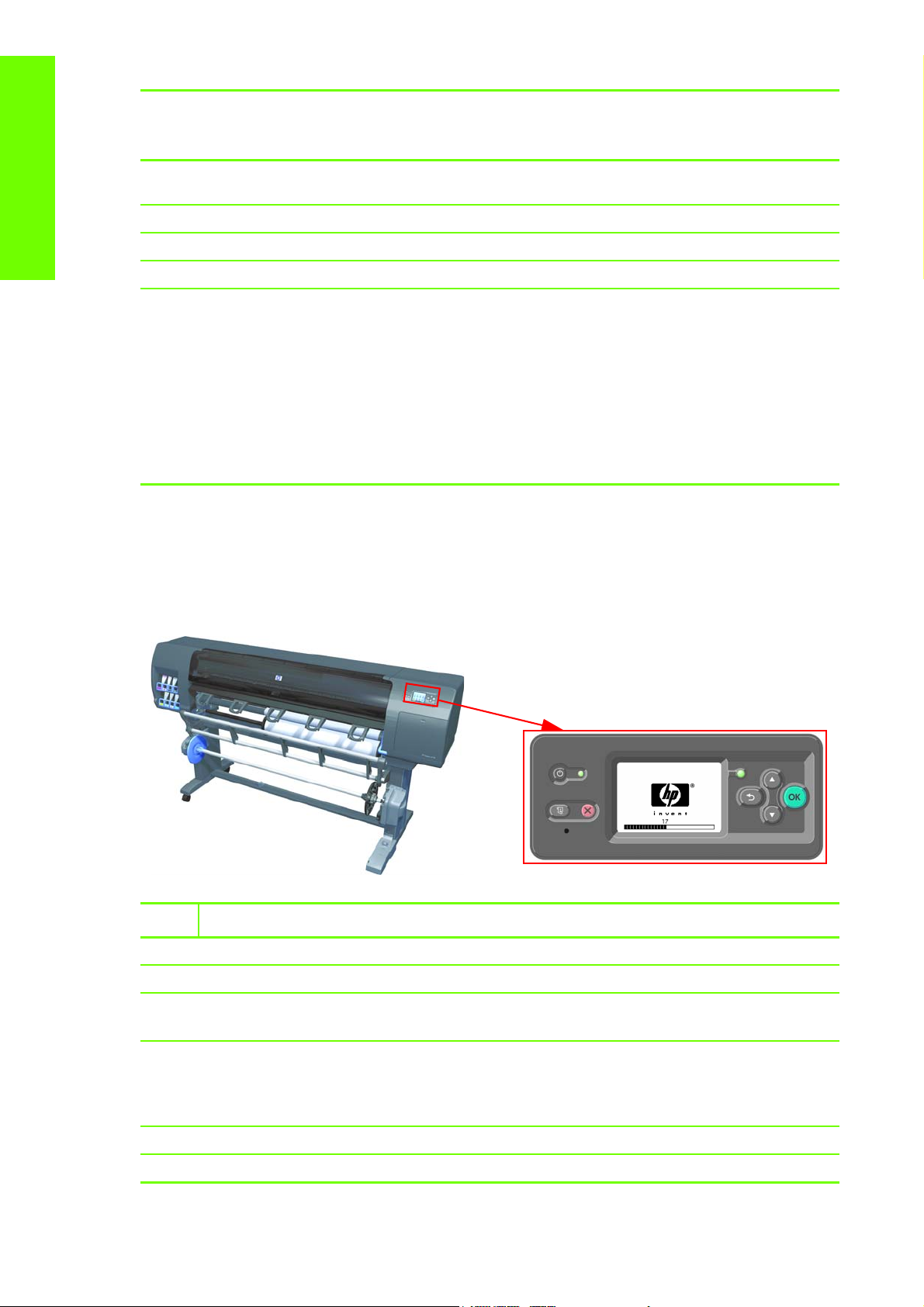
1. If the Printer's Power-Up process stops when the front panel is displaying the number 17, this indi-
cates that there is a problem with the file system on the Printer's Hard Disk Drive, so the Printer is
checking the whole file system and making any necessary corrections. This problem can arise when
there has been a power cut while the Printer was switched On, or if there is a physical problem with
the Hard Disk Drive.
Checking the whole file system normally takes about half an hour (but could take much
longer). There is nothing that can be done to speed up the file checking process. If you turn
Off the Printer during the checking process, the file system check will restart whenever you
turn it On again.
If you experience this problem repeatedly when there has been no power cut, then this
could mean that the Hard Disk Drive is faulty. In this case, replace the Hard Disk Drive
See page 377.
2. If the printer's start-up process stops when the front panel is displaying any number between 1 to
30, then try the following:
⇒
• Switch the Power OFF from the back of the Printer and disconnect the Power cord. Reconnect
the power cord and power On the Printer.
If the Printer continues to stop during the power-up process, replace the
•
page 377.
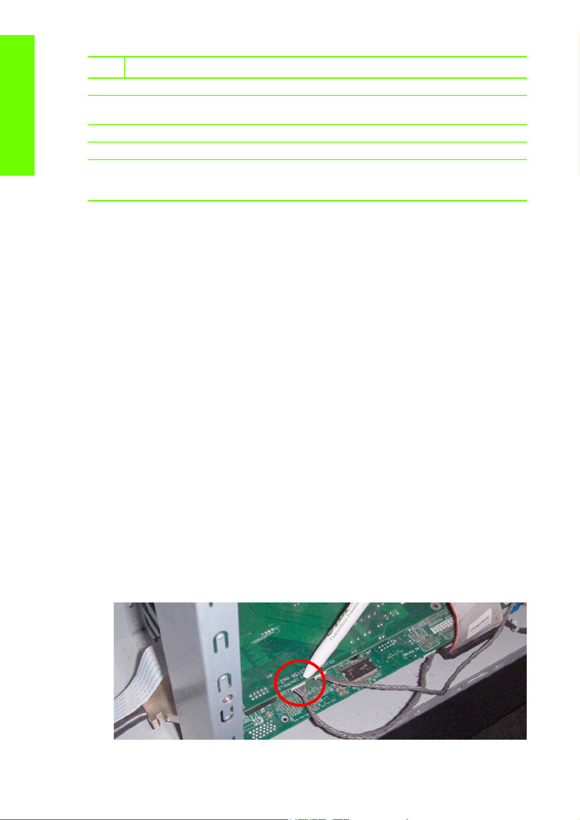
Troubleshooting OMAS problem
A problem with the OMAS board may cause the printer to display a 50.2:10 service error, this can
be fixed by checking the following connections.
1. Check the CAN Cable is correctly connected.
Hard Disk Drive ⇒ See
14 Chapter 1 Troubleshooting
Page 25
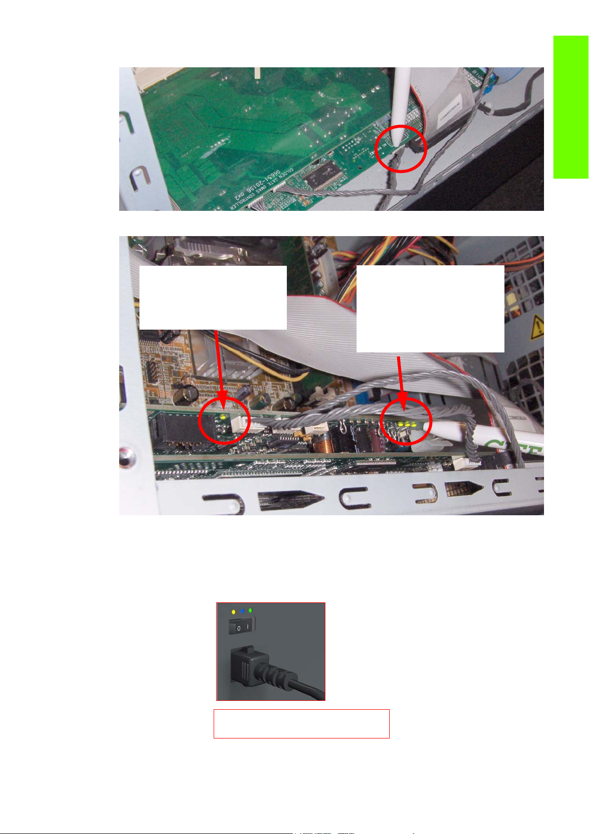
2. Check the other end of the CAN cable is also correctly connected
This LED only comes on for the first
20 seconds after the printer is
turned On. When the firmware has
succesfully loaded into the memory
the LED will switch OFF.
These LEDs come On and stay lit.
From right to left:
1st LED=24 volts
2nd LED=5 volts
3rd LED=3.3 volts
Amber is on the Left
Blue is in the center
Green is on the Right
Make sure you look directly at the LEDs
and not at an angle.
3. Check the LEDs under the OMAS board.
Troubleshooting
Using the Power Switch LEDs to Troubleshoot
In certain circumstances, the LEDs located on top of the power switch (located at the rear of the Printer)
Using the Power Switch LEDs to Troubleshoot 15
can help to troubleshoot the Printer. The LEDs can either be ON or Off and using different combinations
can indicate different problems:
Page 26
1. When only the Amber LED is On:
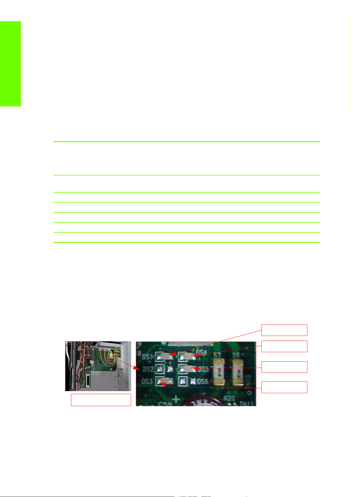
Interconnect PCA
DS5: 5V
DS3: 5Vsb
DS1: 24V
DS4: VPOWER2
• The Printer has been switched Off from the Front Panel (after having pressed the On/Off but-
ton).
• The Power Supply Unit only delivers a 5 V “Standby”; power that is needed to restart the Printer
after the Front Panel On/Off button is pressed (the Formatter/Main PCA will initiate the Printer
to start).
Troubleshooting
2. When the Blue LED is On: Deliver standard “ATX” power for the Electronics Module PCAs (+12V,
+5V, -5V, -12V, etc...). All the functions of the Electronics Module are fully operational (EWS, etc...).
3. When the Green LED is On: Deliver “analog” 24V and 42V to enable printing.
The Printer monitors and reports different signals: PSU fan issues, 24V and 42V delivery failures (specific
System Error reported pointing to PSU failure).
PSU Blue
LED
Status
ON OFF Red (Front Panel Black)
ON OFF Green (flashing) Initializing
ON ON Green Ready (but not printing)
ON ON Green Printing or preparing to print
OFF ON Any Not possible
ON ON Red (Front Panel Black) Not possible
PSU
Green
LED
Status
Left LED (on Front
Panel) Status
Using the PCA LEDs to Troubleshoot
Printer Status
Standby (with Embedded Web Server up and
running)
In certain circumstances, the LEDs located on the Interconnect PCA and PrintMech PCA can help to
troubleshoot the Printer. The LEDs can either be ON or Off and using different combinations can indicate
different problems.
Interconnect PCA
The following illustration shows the locations of the LEDs on the Interconnect PCA
5V - Comes from the PSU after the fuse on Interconnect PCA. Used to power On Front Panel and some
Interconnect Electronics. Should be ON at the same time as Blue Power Switch LED.
5Vsb - Comes from the PSU after the fuse on Interconnect PCA. Used to power On the Printer from the
Front Panel. Should be ON at the same time as Blue or Amber Power Switch LED.
16 Chapter 1 Troubleshooting
Page 27
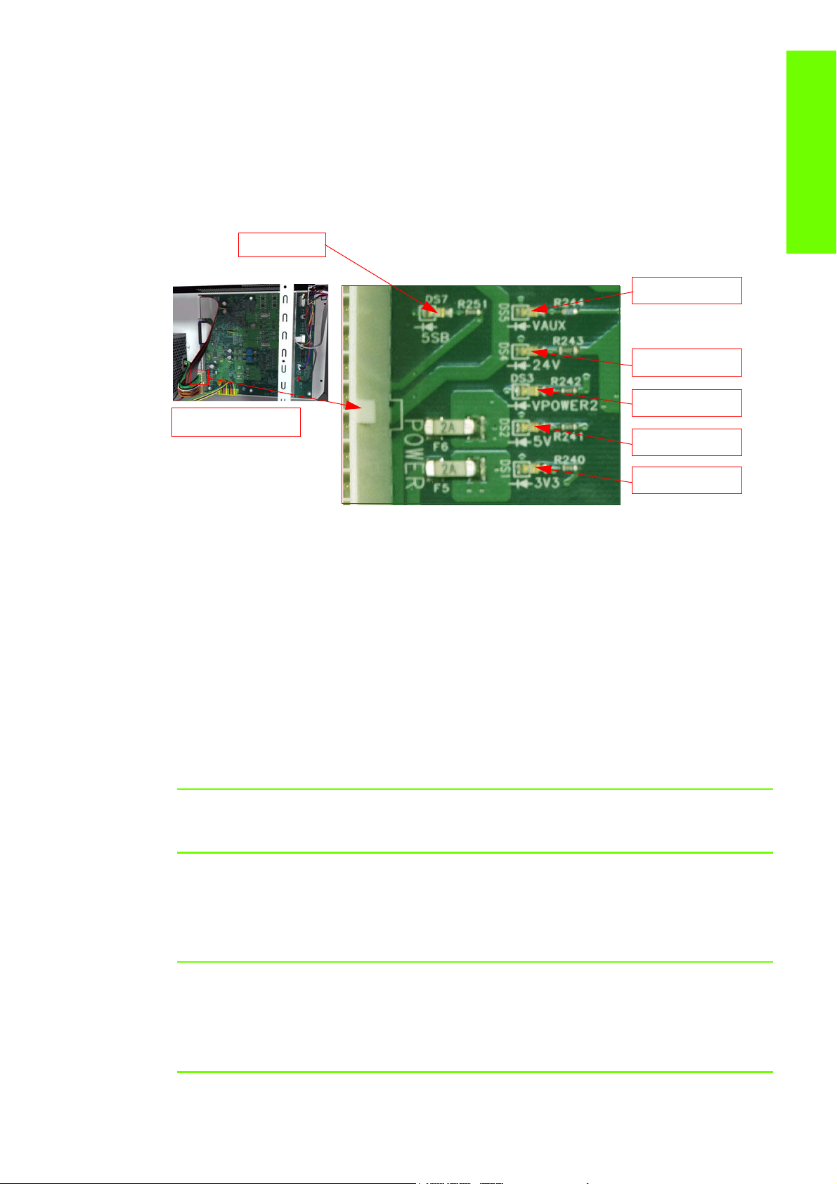
24V - Comes from the PSU after a fuse on the PrintMech PCA.
PrintMech PCA
DS3: VPOWER2
DS7: 5Vsb
DS1: 3V3
DS2: 5V
DS4: 24V
DS5: VAUX=12V
VPOWER2 - Comes from the PSU (42V) after a fuse on the Interconnect PCA. Used to power the Carriage
PCA. Should be ON at the same time as Green Power Switch LED.
PrintMech PCA
The following illustration shows the locations of the LEDs on the PrintMech PCA.
5Vsb - Comes from the PSU after the fuse on PrintMech PCA.
3V3 - Comes from the Power Supply Unit.
5V - Comes from the Power Supply Unit.
Troubleshooting
VPOWER2 - Comes from the PSU (42V) after a fuse on the PrintMech PCA.
VAUX - Comes from the PSU (12V) after a fuse on the PrintMech.
Identifying faults from LED status
Use the following procedure to identify faults from the status of the LEDs.
1. If the Printer cannot be turned ON:
Signal LED on
Interconnect
PCA
5Vsb OFF ON Amber
5Vsb ON OFF Amber
Using the PCA LEDs to Troubleshoot 17
LED on
PrintMech
PCA
Power
Switch
LED
Corrective Action
•
Check the connection between
the PSU and the Interconnect
PCA.
• If connection OK, replace the
Interconnect PCA
⇒ See page
357.
•
Check the connection between
the PSU and the PrintMech PCA.
• Make sure that ALL cables
between the PSU and PrintMech
are not damaged and are connected correctly.
Page 28

Troubleshooting
Signal LED on
Interconnect
PCA
LED on
PrintMech
PCA
Power
Switch
LED
Corrective Action
•
Check the connection between
the PSU and the PrintMech PCA
Amber
5Vsb OFF OFF
2. If the Printer starts (after having pressed the ON button on the Front Panel) but the front Panel
remains black:
or no
LED
and Interconnect PCA.
• If connection OK, check that
power reaches the PSU (check the
power outlet).
• If power reaches PSU, replace the
⇒ See page 379.
PSU
Signal LED on
Interconnect
PCA
LED on
PrintMech
PCA
Power
Switch
LED
Corrective Action
•
Check the connection between
the PSU and the Interconnect
5V OFF ON Blue
PCA.
• If connection OK, replace the
Interconnect PCA
⇒ See page
357.
Check the connection between
•
the Front Panel and the Interconnect PCA.
5V ON ON Blue
• If connection OK, replace the
Interconnect PCA
384 and the Front Panel
⇒ See page
⇒ See
page 292.
3. The Printer is up and running, or may have a System Error at the end of the power-up sequence. For
the Carriage PCA connection, perform the Scan-Axis Test
Signal
LED on
Interconnect
PCA
LED on
PrintMech
PCA
Power
Switch
LED
⇒ See page 97:
Corrective Action
5V OFF ON Blue
24V ON ON
24V OFF OFF
18 Chapter 1 Troubleshooting
Blue
and
Green
Blue
and
Green
Check the connection between
•
the PSU and the Interconnect
PCA.
• If connection OK, replace the
Interconnect PCA
⇒ See page
357.
Check the System Error that is
•
produced and run the corresponding Diagnostic Test (either
Scan-Axis or Media-Axis Test.
•
Check the connection between
the PSU and the PrintMech PCA
and Interconnect PCA.
• If connection OK, run the Elec-
tronics Module Test to further
diagnose the problem.
Page 29

LED on
Signal
24V OFF ON
Interconnect
PCA
LED on
PrintMech
PCA
Power
Switch
LED
Blue
and
Green
Corrective Action
•
Check the connection between
the PSU and the Interconnect
PCA.
• If connection OK, run the Elec-
tronics Module Test to further
diagnose the problem.
Check the connection between
•
24V ON OFF
Blue
and
Green
the PSU and the PrintMech PCA.
• If connection OK, run the Elec-
tronics Module Test to further
diagnose the problem.
4. On the PrintMech PCA, if the 3V3 LED is ON, 5V LED is ON, ERIDANI LED is ON, VAUX LED is ON
and the VAN LED is OFF, then try the following:
• Run the Electronics Module Test to further diagnose the problem.
Troubleshooting
• Replace the PrintMech PCA
5. If the Power Switch LED is Green and the 3V3 LED is ON, 5V LED is ON, ERIDANI LED is ON,
VAUX LED is ON, VAN LED is ON and the VPOWER2 LED is OFF, then try the following:
• Check the connection between the PSU and the PrintMech PCA.
• Run the Electronics Module Test to further diagnose the problem.
• Replace the PrintMech PCA
⇒ See page 384.
⇒ See page 384.
How to Interpret the Service Information Pages
The Service Information Pages contain the following information:
• Current Configuration
• Current Information.
• Usage Information.
• Event Logs.
• Calibration Status.
• Connectivity Configuration
• All Pages.
It is possible to print the Service Information Pages either through the Front Panel or through the Embedded
Web Server:
• Front Panel: Setup menu ⇒ Information Menu ⇒ Internal Prints ⇒ Print Service Information.
How to Interpret the Service Information Pages 19
Page 30
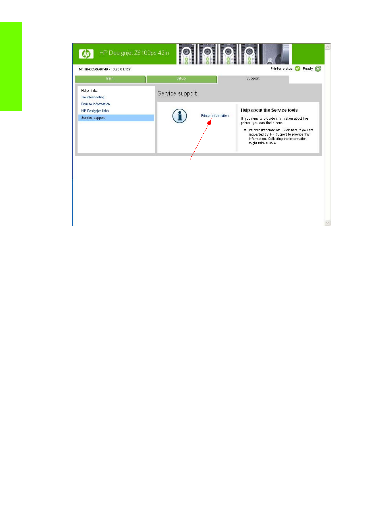
Troubleshooting
Printer Information
• Embedded Web Server: Support tab ⇒ Service Support ⇒ Printer Information.
Even if the Printer cannot print, the Information Pages are still accessible through the Embedded Web
Server.
Main Characteristics
• Only available in English (except the current information page).
• From the Front Panel, you can choose to print ALL pages or just select the specific pages that are
needed. If ALL pages are printed:
• Nesting is turned ON automatically (and turned OFF once all the pages have been printed).
• Nesting cannot be mixed with other jobs in the queue.
• Each page can be printed from the Web browser when using the Embedded Web Server.
• Each page can be sent by e-mail from the Web Browser when using the Embedded Web Server
(File ⇒ Send ⇒ Page by E-mail) .
• You can see the same information through the Front Panel or the Embedded Web Server.
20 Chapter 1 Troubleshooting
Page 31

Current Configuration
This page contains full details of the current configuration of the Printer.
Troubleshooting
How to Interpret the Service Information Pages 21
Page 32

Current Media, Printhead and Ink Information
This page contains the following information:
• Current Printer Configuration.
• Paper Loaded Information.
Troubleshooting
• Current Printhead Kit Information.
• Current Ink cartridge Information I and II.
The first two lines are available at the beginning of each Service Information Page and contains standard
information (like Service ID, Firmware version).
22 Chapter 1 Troubleshooting
Page 33

Printer Usage Information
This page contains the following information:
• Printer Usage.
• Usage per Printhead Slot.
• Usage per Cartridge Slot.
• Media Usage per Media Type.
• Component Usage.
• Spittoon Usage.
• Preventive Maintenance Usage.
Troubleshooting
How to Interpret the Service Information Pages 23
Page 34

Media Used Sections
• Total media used in the Printer.
• Media used for each media type.
Troubleshooting
It is possible that the sum of the media used for each media type is lower that the total
amount of media used in the Printer. This is because only the total media used in the Printer
is saved in the backup EEROM which is located in the ISS PCA. When the Hard Disk Drive
is replaced, the total media used per media type is reset to zero (0), but the total media
used is recovered from the backup EEROM.
Printhead Section
The Printheads section displays the Printhead usage per slot.
• Total Insertions: This is linked with the crane of the Ink Supply Tubes. When the Ink Supply Tubes
are replaced, the total insertions amount will be reset to zero (0).
Cartridge Section
The Ink Cartridges section displays the ink usage per cartridge.
Preventive Maintenance Section
Once the value reaches 100%, the corresponding Preventive Maintenance Kit should be used. For further
details, refer to Chapter 9 - Preventive Maintenance.
24 Chapter 1 Troubleshooting
Page 35

Component Usage
One cycle is counted when the Carriage makes one movement to the left of the Printer and then returns
to the right.
Troubleshooting
To find the total of Monochrome ink consumed in cc use the the formula ^0.61. Example: For a value
marked as 11504, use the formula ^0.61 to convert it to cc=300cc (11504
Spittoon Section
This section contains information on the different Spittoons located in the Printer.
Event Logs
This page contains the following information:
• Last 20 System Error Codes (which prevented the Printer from booting).
• Last 20 System Warnings (which did not prevent the Printer from booting, but which required the
user to acknowledge the problem).
• Printhead Error log.
0.61
=300).
How to Interpret the Service Information Pages 25
Page 36

System/Warning Error
• The Line and Internal Code do not provide much information, but are useful in the case of
escalating a problem to the division (different internal error codes can point to the same error code
(e.g. 01.10:10)).
• Media Usage (in square meters) and Date (from the Printer’s Internal Clock (RTC)) help you to
understand if the Printer has been used (media usage) and how much time has passed since the last
Troubleshooting
error.
Printhead Error Log
• Printheads ago: History of the last three Printheads used (’0’ represents the current Printhead used).
• Status:’0’ = Working,’1’ = No Pen Detected,’2’ = Replace,’4’ = Reseat,’8’ = Remove.
• % Ink Used: Percentage of the Warranty life (1000cc).
• Error Code: Specific error code generated by the Printer when the Printhead has been replaced.
• Max Recovery:
• 0: No manual Printhead recovery has been performed on the Printhead.
• 1 or higher: At least one Printhead recovery has been performed.
Calibrations Status
This page contains the following information:
• General Calibrations (performed by Service Engineers).
26 Chapter 1 Troubleshooting
Page 37

• Media Specific Calibrations (performed by the User).
Troubleshooting
General Calibrations
• Printhead Alignment relates to the Printhead Alignment which changes to ‘pending’ when a
Printhead is replaced and the Printhead Alignment has not been performed.
NOTE: When a component is replaced, the corresponding calibration is NOT automatically
set to ‘NOT DONE‘. This is because the Printer does not know that there is a new part
installed.
• Drop Detector relates to the Drop Detector or Service Station calibration.
• Line Sensor relates to the Line Sensor Calibration.
Media Specific Calibrations
This section shows the following for each type of media:
• Media Name.
• Color.
• Paper Advance.
How to Interpret the Service Information Pages 27
Page 38

Connectivity Configuration
This page contains full details of the current configuration of the Printer.
Troubleshooting
28 Chapter 1 Troubleshooting
Page 39

When the main window is open and the printer is printing (safety compliance)
We describe the details of the behavior of the printer when the window is opened while the carriage is
moving
If the main window is opened while the printer is doing something, be it a swath of a print job or a system
task, the printer will:
1. Before the carriage stops, it will finish whatever it was doing when the window was opened. It will
not finish an image it was printing, but it will finish the current swath, so as to avoid any impact on
image quality. If it was performing a system task it will finish it before stopping.
2. If the carriage finishes on the left side of the printer, the carriage will always slowly move to the right
side of the printer,
3. The printheads will be placed in their 'capping' positions.
Here are some different scenarios of what happens when the window is opened:
• If the printer is printing an image when the window is opened: The carriage will not stop
immediately, the printer will finish the swath and then stop. If the cover is then closed, the printer will
start to print from the position it was stopped.
• If the printer is cutting the media: The carriage finishes the cutting procedure.
• If the printer is checking the SKEW while loading the media: During the skew check, the printer does
small movements of the carriage on the right side of the printer, and also moves the media when
needed. This procedure checks that the edge of the media is moving laterally or not. If the window is
opened while the printer is checking the media SKEW, the printer will complete the skew procedure
(and it will continue well after the window has been opened). This is the only case when the printer
will not stop the carriage at the end of a lateral movement (as a swath)..
Troubleshooting
The safety system in place is designed to detect an object in the path of the carriage as it moves across
the printer, any object encountered will cause the system to shut down the driver motor in the carriage.
This method of ensuring safety is considered sufficient by the regulatory agencies that inspect and assess
the product prior to its placement in the market. The window and its switch are considered a
‘supplementary’ safety feature, and as such the behavior of the switch has been adjusted as a trade off
between the level of safety provided and the printer’s functionality.
General RIP tips and tricks
Here are some general tips and tricks to ensure smooth operation from the RIP to the HP Designjet Z6100
printer:
• Upgrade the printer’s firmware to the latest available version.
• Disable the queue of the printer (from the front panel -> Job Management -> Job Management
options -> set queue to 'disable'.
• Ensure that the Onyx RIP is using port 9100 to communicate with the HP Designjet Z6100, otherwise
the job might be clipped (the reason for this is some other ports have file size limitations).
• If you find that the PC which is running the RIP starts to slow down, or that the carriage is stopping
between swaths while printing:
• Uninstall the HP Easy Printer Care, the Color Center and/or the HP Printer Utility if these are
installed on the PC running the Onyx RIP.
• If you are printing from the Onyx RIP, disable the Best fit function (nesting algorithm, to be
turned off), this is mainly when printing on a 60" printer.
When the main window is open and the printer is printing (safety compliance) 29
Page 40

• Network connection : Ensure that a Gigabit Ethernet connection is used between the PC and
the printer to provide sufficient network throughput. To ensure that the traffic between the RIP
and the printer do not disrupt your other network traffic, please use a Gigabit network switch
(not a hub).
• For a variety of reasons we do not recommend using a crossover LAN cable (direct connection
between the printer and the PC)
Troubleshooting
• When printing from an Onyx RIP, do not try to print on any 'custom media', else a 79:04 will be
displayed on the front panel of the printer. This is media selected from the front panel under the
“custom” category, created from the Color Center/Easy Printer care/HP Printer Utility or when
loading a newer media profile from the Embedded Web server. This issue is fixed in version 7.1 of
the Onyx RIP.
• For halftone RIPs: If you notice that the RIP time is longer when printing on the Z6100 than when
printing on the HP Designjet 5500 printer, this is caused by the following factors:
• The 'halftoning resolution' is higher on the HP Designjet Z6100 (for example: 600x1200dpi, or
1200x1200dpi) compared with the HP Designjet 5500 (all printmodes are 600x600dpi).
• The number of colors is higher, from 6 (HP Designjet 5500) to 8 (HP Designjet Z6100).
• It is entirely possible that the RIP time increases by a factor between 2 to 6, depending on a
variety of factors including: the printmode selected, the file complexity, the PC used and so on.
Also, the amount of data sent to the printer is much greater (by up to a factor of 4), requiring
more bandwidth over the network.
Notes:
Applications (Vendors) that drive the HP Designjet Z6100 Series through the 'halftone path' :
• Postershop and ProductionHouse (ONYX), ImagePrint (Colorbyte), ColorProof04 (GMG),
(Kodak), Newscolor (Newscolor), Founder (Founder), Softrip (Wasatch), Colorburst, Proofgate /
Photogate and ProductionServer (Colorgate), FlexiSign and Photoprint (Scanvec), ApogeeX (Agfa),
ProofMaster (Perfectproof), Liveprint (Dinax).
Applications (Vendors) that drive the HP Designjet Z6100 through the 'Contone path':
• DesignerEdition and ColorProof (EFI), Posterjet (Eisfeld), Oris Colortuner (CGS), Interplot
driver (Bentley), Metadimension (Heidelberg), Shiraz (AIT), Starproof (Compose), Daylight RIP (SCP)
Applications (Vendors) that are able to use both the ‘Contone’ and ‘Halftone’ paths:
• ReproShop, VisualRIP (Caldera), (ExpressDigital), Postershop and ProductionHouse (ONYX) from
version 7.1
These lists are provided for information only and are subject to change without notice. For more
information, please contact the specific application vendor.
Frequently Asked Questions
For customers printing from the ONYX RIP to the HP Designjet Z6100 Printer:
Question: What should I do when I get a 79:04 displayed on the front panel when printing from the
ONYX RIP?
Answer: Upgrade to the latest firmware (at least FW 6.0.0.9) or disable the printer queue (from the front
panel -> Job Management 0> Job Management options -> set queue to 'disable') If you are getting the
79:04 when printing on any 'custom' media, please upgrade the ONYX RIP to version 7.1
Question: My image is getting clipped when printing from the ONYX RIP, how can I solve this?
30 Chapter 1 Troubleshooting
Page 41

Answer: From the ONYX RIP, within the properties of the printer, set the port to 9100 (instead of LPR).
The LPR port has a maximum file size limitation.
Question: When printing from the ONYX RIP, my PC becomes too slow and/or the carriage stops
between each swath, how can I troubleshoot this problem
Answer: A number of different factors can cause this to happen. Here is a troubleshoot checklist which
should solve the majority of issues:
1. Uninstall the HP Easy Printer Care, the Color Center and/or the HP Printer Utility. If you need to use
this tool, you might be able to install them on another PC.
2. Disable the Best fit function (nesting algorithm, to be turned off), this is mainly when printing on a
60" printer.
3. Make sure that there is a 1GB connection between the printer and PC, and that both the PC and the
printer are alone, behind a switch.
4. For a variety of reasons we do not recommended using a cross over LAN cable (direct connection
between the printer and the PC).
5. As the number of colors, and the printing resolution of the HP Designjet Z6100 compared to the HP
Designjet DJ5500 is higher, the ripping time will be higher.
6. Use the ONYX 7.1 with the latest ONYX drivers for the HP Designjet Z6100. You will then be able to
print through the 'contone' path. This has a rendering/ripping resolution from 300ppi (FAST and
NORMAL-FAST) to 600ppi (NORMAL and BEST), depending of the image quality setting selected.
However, Contone drivers have less control of the color and any media profiles will need to be
redone (but the creation will be much quicker and it is much simpler).
Troubleshooting
Question: On my HP Designjet 5500 printer, I was able to select any printmode
(resolution, number of passes, ...) and on the HP Designjet Z6100, I have got only 4 choices! For
example, when loading a photo media, I cannot select a number of passes lower than 6. What can I do?
Answer: Upgrade to firmware GG6.0.0.9 and upgrade the RIP to ONYX RIP 7.1. You will then have
many more choices of printmode (around 8-10 per media types selected on the front panel).
Question: When printing on the HP Designjet Z6100 form the ONYX RIP, I get an error on the front
panel: '61:01, media miss-match'. What can I do?
Answer: Upgrade to firmware GG6.0.0.9 and upgrade the RIP to ONYX RIP 7.1. After doing this the
probability of having this error is significantly reduced (more print modes available plus warning from the
ONYX RIP in case of incompatibility).
Question: I am using a specific image quality in my HP Designjet 5500, and I cannot find the same
name on the HP Designjet Z6100, which one should I select to get the same image quality while printing
faster?
Answer: Refer to the table at the beginning of this newsletter ‘Recommended Print Modes’ . This is a
print mode look-up table, showing the optimized upgrade path (mainly for HP media).
How to troubleshoot the 79:04 System Error
Introduction
The System error 79:04 is a generic firmware error (equivalent to a blue screen in Windows). It’s the
System Error that the printer will display when an unknown exception occurs that cannot be pointed to by
any specific subsystem of the printer.
How to troubleshoot the 79:04 System Error 31
Page 42

Since this is a generic error, there can be multiple causes behind it. This document will cover the most
probable causes behind a system error 79:04 and will recommend the most efficient troubleshooting steps
to resolve customer issues.
One important point to mention is that, although 79:04 system errors can be caused by a hardware
malfunction, the vast majority of 79:04 system errors are pure software or firmware issues. In these cases
the issue can only be solved by determining the root cause and implementing a solution. The solution can
usually be applied by either correctly configuring a selection, updating the printer’s firmware/software
Troubleshooting
that is being used or by fixing an error in the code).
Possible causes
Since the 79:04 system error is a generic error, the number of possible causes behind it is large. The
majority can be grouped, however, into the following groups:
Job related SE79:04
A specific print job that is not correctly formatted for the printer or that is not correctly processed by it can
trigger a 79:04 system error.
The incorrect format or processing can come from two sources:
• Incorrect commands in the job itself. For example, a PS job with some commands that do not have
• Issues applying to the settings in the job
the correct PS format.
Possible symptoms
79:04 caused by a print job always have the same symptoms:
1. The job is received by the printer and starts to process.
2. In the middle of the processing, the printer stops and displays 79:04.
3. The printer will display the 79:04 system error again immediately after reboot. This is due to the fact
that the printer will try to reprint the job, which is pending in the queue, after reboot.
4. After the second reboot, the printer will start up normally
5. If the same job is sent again, it will always produce a 79:04 system error
These types of 79:04 system errors are normally caused by jobs that have been generated by 3rd party
applications (RIPs, 3rd party drivers, files exported by an application to PS, PDF, HP-GL/2, RTL, … or any
other format supported by the printer). Jobs generated by HP drivers will not normally generate 79:04
system errors, since the output that our drivers generate is very controlled and has been designed taking
into consideration the characteristics of our printer’s language interpreters.
There is an exception to this general rule: there are certain applications that can generate their own PS
code (Adobe PhotoShop, Adobe Illustrator, Adobe Acrobat, Corel Draw, Freehand, QuarkXpress, …).
When used with a PS driver, these applications generate the output PS themselves, instead of using the
driver’s rendering capabilities. This is known as PostScript pass-through. So, when using an HP PostScript
driver together with an application that has PS passthrough capabilities, the PS code that comes into the
printer has not been rendered by the HP driver, and, should the source file contain any PS commands that
are not correctly processed by the printer, a 79:04 system error could occur even though an HP driver is
being used.
Solutions and workarounds
When a job consistently generates a 79:04 system error, it is either because of a issue in the printer’s
firmware or because of a defect in the job itself (when it has been generated by 3rd party SW). In order
to identify the cause and find out a solution, these issues should always be immediately escalated to the
GBU through the GCC.
32 Chapter 1 Troubleshooting
Page 43

Also, there are a set of workarounds and short term solutions that can be tested in order to get the customer
up and running in the shortest possible time:
1. Send the job using a variety of different settings. Many times, the issue is caused by a combination
of the job contents combined with some specific setting(s).
2. If the customer is sending the file directly to the printer, try using the HP driver instead
3. If the issue is occurring when printing through the HP PostScript driver from an application with PS
passthrough, try changing the options in the application so that it prints PS as raster (the option is
typically located in the “Advanced” options of the application’s printing dialog).
Data related SE79:04
HP Designjet printers have Hard Disks and non volatile memories that contain data bases and files that
can be modified with user data. Some examples include:
• The printer’s queue
• The hard drive partitions that contain user jobs
• The data base that stores the printer settings
• The data base that stores accounting information
Some of this data is accessed by the printer at start up, and some others are accessed as needed.
If any of this fields contains corrupt data or data with characters or values that cannot be correctly
processed by the printer, a 79:04 system error may occur.
Possible symptoms
There are two different types of symptoms for data related 79:04 system errors:
1. When the corrupt data is accessed during start up:
Troubleshooting
a. The printer will display a 79:04 during the start up process
b. Switching the printer off and on again will not solve the issue. The printer will continue display-
ing the 79:04 system error until the corrupt data has been cleared through a service procedure
2. When the corrupt data is accessed during normal printer operation
a. The printer will start up normally
b. When the data is accessed (for example while printing, while navigating the queue or when
changing some settings), the printer displays a 79:04 system error
c. The printer can reboot normally
d. When the data is accessed again (typically, under the same conditions as in step “b”), the
79:04 system error is displayed again
Solutions and workarounds
Many times, data related 79:04 errors are resolved by means of hardware intervention. Since data is
stored in physical components (RAM, EEROM and Hard Disk), replacing these components with new ones
which are empty usually solves the problem. However, there are quicker and more effective solutions to
these types of errors:
1. Clear all information that has been introduced by the user using the standard tools available in the
printer:
a. Delete all jobs from the queue (from the Front Panel or the EWS)
b. Reset to factory defaults to clear the user’s configurations and calibrations
How to troubleshoot the 79:04 System Error 33
Page 44

c. Delete any non standard paper preset in the printer (both the ones that have been created by
the user and the ones that have been installed as OMES profiles through the EWS or the HP
Printer Utility)
2. If step 1 did not resolve the issue, you can use Service Tools to clear additional information that
could be causing the issue:
a. Start the printer in Diagnostics Boot Mode
Troubleshooting
b. Perform an EEROM reset
3. If step 2 did not resolve the issue, it is possible to completely clear the information on the Hard Disk
and the different EEROMs, leaving them in an equivalent state to a new part:
a. Access the Service Utilities Menu
b. In the Secure Disk Wipe menu, set the Sanitize level to “Unsecure mode”
c. Execute the Disk Wipe. This takes 45-75 minutes and it will completely clear all partitions in the
Hard Disk which contain user data, including the partition where the Operating System is
installed. After the disk wipe has completed, a backup firmware version will automatically be
installed from a backup partition to allow the unit to start up. This firmware version is very old.
d. The firmware in the printer should be upgraded to the latest official version as soon as the
printer has restarted.
After step “c”, any 79:04 which is caused by corrupt data in the printer will be solved.
Important note:
It is possible that the corrupt data came to be in the printer as a consequence of some activity in the
customer’s workflow. In this case, it is possible that the issue will happen again. In these cases, it is very
important to understand the sequence of events in the customer’s workflow that led to the error occurring.
Once the error can be traced in the customer’s workflow, escalate the issue to the GBU (through the GCC).
This is done to implement any changes in the printer’s firmware that can prevent these issues occurring
again.
Network related SE79:04
Most HP Designjet printers have built-in networking capabilities. Network settings can be set manually,
but in the majority of cases, they are obtained automatically from the printer. These settings include many
different fields, such as IP address and subnet mask, available gateways, host and domain names, etc.
In some cases, there can be issues in the firmware that can cause a certain value in one of these fields to
be interpreted incorrectly, and this can lead to a 79:04 system error.
Symptoms
There is no single set of symptoms that can absolutely pinpoint a network related 79:04 system error.
However, the following guidelines can be applied:
• It can happen at start up or when accessing the Network Configuration section of the FP
• In both cases, repeating the action with the LAN cable disconnected does not cause the 79:04 to
occur
Solutions and workarounds
In the majority of cases, these issues will be due to an issue in the printer’s firmware. As soon as the
conditions where the issue happens can be understood, it should be escalated to the GBU through the
GCC.
At the same time, the following short term solutions and workarounds can help the customer to get up and
running in the shortest possible time:
34 Chapter 1 Troubleshooting
Page 45

1. Disconnect the network cable to be able to boot the printer and change network settings
2. In the Network configuration menu in the Front Panel, disable any protocols that you are not using,
including IPv6, SNMP and WebServices.
3. If step “2” does not work, try setting a manual configuration of the device:
a. Enter the correct subnet mask and an IP in the valid range
b. In the GateWay field, set the same value as in the IP address field
c. Do not set a host name or a domain name
4. If step “3” does not work and the customer is using the network card which is part of the printer, try
using an accessory Jetdirect card instead.
User Interaction related SE79:04
In some cases the printer may not react as expected when a certain set of conditions coincide. In these
cases, if the printer doesn’t know how to react, it may simple display a 79:04 system error and force a
reboot. Some examples (not real) that can help to illustrate this:
• An error occurs when a job is cancelled when it is at the “Finishing print” state and when the queue
is disabled
• An error occurs if the Window is opened while the printer is checking the printheads
These errors will most likely only happen in very specific corner cases that have not been identified during
the development or the qualification of the printer, so normally, they do not severely impact the customer,
as they do not affect their regular working flows.
Symptoms
The symptoms here are as numerous as the number of possible interactions between the user and the
printer. In any case, it’s possible to identify the steps that caused the error to occur and avoid them as the
steps will always be the same with no variance.
Troubleshooting
Important: An major element in determining the error is what the state the printer was in at the time the
error was displayed. Actions the user has made when the printer is drying for example can produce an
error, whereas the same action when the printer is doing something else (or is idle) may not produce any
errors.
Solutions and workarounds
The recommended action plan in these cases is to identify the previous steps that caused the error and:
1. Escalate the issue to the GBU through the GCC in order to have it corrected in the firmware.
2. Recommend to the customer that they try to avoid the same steps to prevent the issue
3. If the conditions that cause the error are in the customer’s regular workflow, try to identify a different
way of achieving the same result out of the printer.
Random SE79:04: Concurrence issues and memory leaks
Some 79:04 errors can happen randomly when the printer is being heavily used. However, it’s impossible
to find a single set of conditions that reproduce the problem. It just happens from time to time, without a
defined pattern.
These random 79:04 can have two different types of root causes:
• Memory leaks: before a program is executed, it allocates the memory it will need. After the
execution is complete, the allocated memory is freed to be used by other programs. If the allocation
or the release of the memory are not properly programmed, every time the program is executed
some memory will be incorrectly labeled (either as used or as free). This is known as a memory leak.
How to troubleshoot the 79:04 System Error 35
Page 46

Troubleshooting
When a program with a memory leak is executed a lot, the memory becomes progressively full
(since it is not properly freed). When the leak becomes too big, the printer is left ‘out of memory’ to
execute new processes and a 79:04 is triggered
• Concurrence issues: there are certain resources that can be accessed by multiple programs or by
multiple executions of the same program (what is known as multiple threads). Access to these
resources must be correctly controlled to prevent unexpected behavior. Issues caused by an incorrect
control of these resources are concurrence issues.
In the following you have a simple example: let’s imagine that there is a counter that controls the
communication between the JetDirect card and the printer’s firmware. Whenever a new packet of
information is sent by the JetDirect card to the printer, the counter increases. When the printer
receives the packet and processes it correctly, the counter decreases. Another process checks the
counter from time to time to see its value and take conclusions from it. If the counter is near 0, it
means that the printer is processing correctly, and if it grows too big, it may mean that there is a
bottleneck somewhere and maybe the JetDirect card throughput is decreased to control its speed to
the printer. However, if the access to this counter is not properly controlled, undesirable effects may
happen: in a real environment, a JetDirect card processes thousands of information packets per
second, so this counter is updated frequently, both by the JetDirect and the printer. If at a certain
point the JetDirect and the printer try to access the counter at the same time and the code is not
prepare to handle this, it may happen that the JetDirect cannot increase the counter because the
printer is writing to it, and what’s worse, that it does not realize this fact. If this happens a few times
each second, it may happen that the counter is decreasing faster than it’s increasing and that at a
certain point it has a negative value. And then, what will the process that is checking this counter
do? Most likely, the process will not be prepared to react to a negative value and will launch an
exception that will trigger a 79:04 system error.
Symptoms
This type of 79:04 always occurs in heavy load conditions, so the symptoms will always be similar to this
pattern:
• A printer that is being heavily used (printing a project or in a reprographics environment) produces
79:04 errors randomly, forcing the user to reboot.
• After rebooting, the printer can be used without any issues for an extended period of time, but if the
workload is consistently high, a random error will occur again.
• The error can never be associated with a specific file. The file that was being printed when the error
occurred the last time can be printed without issues after reboot. And a file that has been printed
without issues several times can trigger the error in the future.
• This error is very dependant of the workflow the customer has. The most common user workflows
have been extensively tested both by HP and by our beta sites, so it is highly unlikely to see random
79:04 issues in these cases. These random issues tend to occur in very specific corner cases, and
cannot be reproduced unless the exact conditions of the workflow are replicated. They normally
happen when sending files generated by external applications (RIPs, 3rd party drivers, etc.).
Workarounds and solutions
Random 79:04 errors are, by far, the most complex ones to diagnose and to fix. The only solutions
available in these cases are:
1. Identify the root cause (either in the files or in the firmware) and fix it in the code, which requires the
intervention of the GBU
2. Test any options available to modify the customer’s workflow and see if any combination of them
solves the issue
In both cases, a profound understanding of the customer’s workflow is necessary. In particular, the
information that is needed is:
• Printer front panel settings
36 Chapter 1 Troubleshooting
Page 47

• Application that is being used; RIP or driver that is being used
• Application/RIP/Driver settings
• Type of output files this application, RIP or driver is generating
• Some sample files that are representative of what the customer is using
• Operating System
• Method of connection to the printer
• A description of the normal flow when the issue occurs and the typical frequency of occurrence (i.e.
once every hour when sending non stop several files, each of them with multiple copies)
With this information, the environment can be replicated in order to try and find workarounds. This is also
the information that will be needed at the GBU to investigate and fix the root cause of this issue once it is
escalated.
Hardware related SE79:04
Hardware is, by far, the least likely cause of a 79:04 system error. Replacing hardware components does
not normally fix the issue and increases the total turn around time in finding a workable solution.
In some cases, a failure in a component in the printer’s electronics may cause a 79:04 system error, since
the printer’s electronics are involved in the execution of the firmware and the processing of jobs. It needs
to be noted, however, that hardware failures in the electronics tend to produce specific system errors that
point directly to the component that is failing.
Troubleshooting
Some HW causes that could be behind a 79:04 error are:
• Defective clusters in the Hard Disk drive. If these clusters are used to execute the firmware or to
process a job, they may produce a 79:04. It needs to be noted however, that most 79:04 errors that
are resolved by an HDD replacement are in fact, data related 79:04 that could have been solved
more efficiently and quickly following the steps in Section 3.
• Defective memory segments. If the RAM memory has some defective segments, a 79:04 may occur
when these segments are used.
• Intermittent defects in the electronic components that are involved in the processing of a job:
Carriage PCA, Trailing cable, Formatter and Print Mech. This is a highly unlikely cause, since defects
in these components will produce subsystem specific errors.
Symptoms
There’s no single set of symptoms behind hardware related 79:04 system errors. The most usual ones,
however are:
• 79:04 during start up. Rebooting the printer may or may not solve the problem
• 79:04 while processing or printing a job. Rebooting the printer and printing the same job does not
always produce the error.
Solutions and workarounds
In the following procedure perform each step as it appears in the list and only move on to the next step
once you are sure the 79:04 error has not been cleared:
1. Reboot the printer in Diagnostics Boot mode and execute the service tests to validate the functionality
of all the electronics components
• Execute the troubleshooting for “data related” system errors, refer to page 3, Data related
SE79:04
How to troubleshoot the 79:04 System Error 37
Page 48

2. Replace the memory
3. Replace the HDD
4. Escalate the issue before replacing any additional parts.
Troubleshooting based on symptoms
Troubleshooting
This section will describe which troubleshooting steps to perform for a 79:04 system error based on the
symptoms of the issue. Perform each step as it appears in the list and only move on to the next step once
you are sure the 79:04 error has not been cleared:
Front panel displays 79:04 at Start-up
• Reboot the printer twice. If the System error has been caused by a job because its in an incorrect
format, rebooting twice will clear the error (the first time after reboot, the printer will attempt to print
the job again, and this will cause the error to re-appear). If rebooting the printer twice solves the
issue, then it is an issue related to the job and you should refer to page 2, Job related SE79:04.
• Upgrade the printer’s firmware. Even if the currently installed firmware version is the latest one, re-
install it. Since the printer cannot start normally, you will need to upgrade the firmware while
booting the printer in Diagnostics Boot Mode. For this, a special file and a special upgrade process
will be needed. You can find the specific information for the printer model you are troubleshooting
on page 13, Appendix A .
• Disconnect the network cable and restart the printer. If this solves the problem, then it is a network
related 79:04 and you should follow the guidelines for this type of 79:04 on page 4, Network
related SE79:04
1. Remove all cartridges, printheads and printhead cleaners (if available). Unload the media. Restart
the printer. If the printer can start normally, insert the consumables one by one until you isolate the
one that is causing the error. Do NOT insert any of the replaced consumables in another printer
2. Restart the printer in Diagnostics Boot Mode and perform the “Electronics test”. If an electronic com-
ponent is identified as faulty, replace it.
• Restart the printer in Diagnostics Boot Mode and Reset the EEROM. If the issue is solved by
this, this is a data related 79:04 system error and you should follow the guidelines, refer to
page 3, Data related SE79:04.
3. If the unit has been used for some time and suddenly has started to show this behavior, replace the
Hard Disk Drive (it may be included with the Formatter in some models).
4. If the issue is new and the issue happens since the first boot, do NOT replace the HDD.
5. If none of the previous steps solved the issue, escalate the issue with the following information:
• Unit information: S/N, P/N, accessories
• Conditions where the problem occurs and conditions prior to the first occurrence of the problem
• The results of the previous 8 steps
• The System Error detailed information (this can be obtained by pressing CANCEL + Down)
• The printer logs.
Front panel displays 79:04 during printer operation – not while sending jobs
1. Reboot the printer.
2. Upgrade the printer’s firmware. Even if the currently installed firmware version is the latest one, re-
install it.
3. Reset the printer to factory defaults
38 Chapter 1 Troubleshooting
Page 49

4. In order to narrow the scope of the issue, try the following:
a. Disable the queue
b. Disable any unused network protocols
c. Disable SNMP and WebServices (if they are available in the printer)
d. Disable “Sleep mode” from the Service Utilities menu
e. Delete any Paper Presets that you may have uploaded or created using the printer Spectropho-
tometer.
5. Restart the printer in Diagnostics Boot Mode and perform the “Electronics test”. If an electronic com-
ponent is identified as faulty, replace it.
6. Restart the printer in Diagnostics Boot Mode and Reset the EEROM. If the issue is solved by this, this
is a data related 79:04 system error and you should follow the guidelines for this type error on page
3, Data related SE79:04.
7. Format the Hard Disk drive. To do so, you will need to start the printer normally, enter the Service
Utilities menu and then the Secure Disk Erase option. Set the Erase method to “Fast Erase” and then
perform the disk erase process. This will take 45-75 minutes and will erase all user information from
the disk, resolving any issue caused by corrupt data. After the erase process, a firmware update will
be required. If this solves the issue, this is a data related 79:04 system error and you should follow
the guidelines for this type of 79:04 on page 3, Data related SE79:04.
8. Try to identify the combination of settings or actions that led to the system error and try to reach the
same result with a different combination. Escalate the issue to fix the original problem.
Troubleshooting
9. If none of the previous steps could solve the issue, escalate it with the following information:
• Unit information: S/N, P/N, accessories
• Conditions where the problem occurs and conditions prior to the first occurrence of the prob-
lem
• The result of the previous 8 steps
• The printer information pages (either printed and faxed or obtained through the Embedded
Web Server)
• The System Error detailed information (it can be obtained by pressing CANCEL + Down)
• The printer logs.
Front panel displays 79:04 while printing
A. While printing a single job
The error happens after a single job is sent. It’s easy to identify which job that has produced the error,
since every time that this same job is sent, the error is replicated.
1. Reboot the printer twice (after the first reboot, the printer will show the 79:04 system error again,
since the printer will attempt to reprint the last job in the queue, which is the one that caused the
issue)
2. If you are using an HP driver, update the driver to the latest version
3. Upgrade the printer’s firmware. Even if the currently installed firmware version is the latest one, re-
install it. Send the job using different print settings. The following ones can be helpful:
a. Try sending the job without selecting a media profile in the driver
b. Try changing the Image Quality settings
c. If you are using the HP-GL/2 driver, try the option “Send job as bitmap”
How to troubleshoot the 79:04 System Error 39
Page 50

Troubleshooting
d. If you are using the PS driver, try using the HP-GL/2 driver instead
e. If you are using the PS driver from an Adobe application (or any other application that can
handle PS), try changing the application’s print settings so that the PS is generated as Raster.
4. Try the following Front Panel settings:
a. Change the Print Language option in the Front Panel from “Automatic” (which is the default set-
ting) to the language that is being printed (PS, HP-GL/2, …)
b. Queue = OFF
c. Start Printing = After processing
d. For PS SKUs, try changing the encoding setting (“Automatic” by default) to Binary or ASCII
5. If you are using a 3rd party application that does not print through the HP driver, try modifying the
printing workflow by:
a. Using an HP driver
b. Changing the settings in the application’s printing dialog
6. If you are using an accessory JetDirect card, try using the internal network connector or USB (if avail-
able).
7. Escalate the issue, providing the following information:
• Unit information: S/N, P/N, accessories
• Conditions where the problem occurs and conditions prior to the first occurrence of the prob-
lem.
• The result of the previous 7 steps
• The printer information pages (either printed and faxed or obtained through the Embedded
Web Server)
• The System Error detailed information (it can be obtained by pressing CANCEL + Down)
• Information on the workflow:
-Operating System
- Application
-Driver
- Settings in the driver and the application
- Settings in the printer
- Connection method and settings:
- The original file along with the information on how to reproduce the issue
- A print to file that can reproduce the issue
• The printer logs.
B. Random 79:04 during continuous printing
The error does not happen with a single job. It happens randomly during continuous printing, normally
while the printer is managing a heavy load (printing a project or in a reprographics environment).
This type of error is caused either by memory leaks or by concurrence issues in the printer’s firmware.
They normally happen in non common environments where these memory leaks or concurrence issues that
have not been detected during qualification have occurred. These issues cause the printer to crash at a
completely random moment during printing, and are not associated to a specific job.
Because of this, troubleshooting these issues is normally quite complex.
40 Chapter 1 Troubleshooting
Page 51

1. Reboot the printer twice (after the first reboot, the printer will show the 79:04 system error again,
since the printer will attempt to reprint the last job in the queue. If the issue continues occurring randomly, continue troubleshooting
2. If you are using an HP driver, update the driver to the latest version
3. Upgrade the printer’s firmware. Even if the currently installed firmware version is the latest one, re-
install it.
4. Try the following changes in the workflow:
a. Change the Print Language option in the Front Panel from “Automatic” (which is the default set-
ting) to the language that is being printed (PS, HP-GL/2, …)
b. Queue = OFF
c. Start Printing = After processing
d. For PS SKUs, try changing the encoding setting (“Automatic” by default) to Binary or ASCII
e. If you are using the HP-GL/2 driver, try sending the job as a bitmap
5. If you are using a 3rd party application that does not print through the HP driver, try modifying the
printing workflow by:
a. Using an HP driver
b. Changing the settings in the application’s printing dialog
6. Escalate the issue with the following information:
• Unit information: S/N, P/N, accessories
• The printer information pages (either printed and faxed or obtained through the Embedded
Web Server)
• The System Error detailed information (it can be obtained by pressing CANCEL + Down)
Troubleshooting
• Information on the workflow:
-Operating System
-Application
-Driver
- Settings in the driver and the application
- Settings in the printer
- Connection method and settings
• Exact information on how to replicate the environment that reproduces the issue, including
some example files that can be sent to the printer to replicate a heavy load environment. These
files will need to be:
- Original application files, if the issue happens printing from an application through our
driver
- Print to files if the issue happens printing from a 3rd party application
How to troubleshoot the 79:04 System Error 41
Page 52

Troubleshooting
42 Chapter 1 Troubleshooting
Page 53

2System Error Codes
• Introduction..................................................................................................................... 44
• System Error Codes and Warnings - Explanation ................................................................. 44
• Continuable and Non-Continuable Error Codes....................................................................47
System Error Codes
43
Page 54

Introduction
Code: 0x1901001
Sev e rity: E rro r
Priority : 30 0 0
Id: 0x 1 01021 a
Description:
STRING_POWER_OFF
File:
73:03
This is the Code that is required
when escalating a problem
System error codes are hexa-decimal based numbers generally caused by internal system errors. The
following pages contain a list of system error codes and their respective descriptions and recommended
corrective actions. Only try one recommended action at a time and check if the error code has
disappeared.
If you have an error code which is not documented in this Service Manual or you have an error which
you cannot resolve, then report the error to the HP Response Center or the nearest HP Support Office.
When reporting the error, have the following information ready:
• Model and Serial Number of the printer.
• Which firmware revision the printer is using (See Note below). Check firmware in Setup Menu /
Information Menu / Show Printer Information.
• The complete error number (See Note below).
• The Service Configuration Print
• The Current configuration sheet.
• Which software application the customer is using (name, version, etc).
.
System Error Codes
NOTE: When reporting the System Error Code, make sure that you supply the full Internal
Error Code and the firmware version. Without this information, HP Support Personnel cannot
help you. To view the Internal Error Code, hold the DOWN key and press the CANCEL key at
the same when the System Error Code is displayed on the Front Panel.
System Error Codes and Warnings - Explanation
System Error Codes explain which component/system is failing and what action should be taken to
resolve the problem.
System Error Codes are displayed directly on the front panel (but can also be seen on the Information
Page) and have been defined in the format XX.YZ. or XX.n:YZ.m.
• XX: Service Part (2 digits).
• n: Service Part Index (if more than one used in the product) - Optional.
• Y: Who should perform the action (1 digit) - (User or Service Engineer).
• Z: Action to perform (1 digit).
• m: additional actions/information to consider (1 digit) - Optional.
44 Chapter 2 System Error Codes
• e.g. Identify the Ink Supply (color and number).
• e.g. Non-authorized ink was detected, PM was triggered or Printhead in/out of Warranty.
Page 55

The following table explains the XX part of the System Error Code or Warning:
Code Component/System
01.0 Main PCA/Electronics Module (Sausalito)
01.1 Add-on Electronics Module (Printmech)
01.2 ISS Electronics Module
02 Carriage
02.1 Carriage PCA
03 Power Supply Unit
05 Formatter
05.1 Fan of the Formatter
05.3 Memory of the Formatter
06 Hard Disk Drive
07 Interconnect PCA
08 Front Panel
11 Trailing Cable
21 Service Station
23 Pressure System (APS)
24 Ink Delivery Tubes
26.n Ink Cartridge (color n)
27.n Printhead (color n)
31 C u t t e r
32 Take-up Reel
38 Output Tray
39 Paper Loading Failure
41 Pa p e r- A xi s M o t o r
42 Scan-Axis Motor
43 Vacuum Fan
44 Aerosol Fan
50 OMAS
51 Window/Door Sensor
51.1 P H C A c c e s s D o o r S e n s o r
52 Drop Detector
53 Media Sensor
54 Media Lever Sensor
55 Line Sensor
56 Drive Roller Encoder Sensor
58 Color Sensor
61 L a n g u a g e I n t e rp re t i n g
61.1 PS Fo n t s M i s s i n g
61.2 File with Passwords cannot be Printed
63 Input/Output through LAN Card
64 Input/Output through USB Port
65 Input/Output (not know what port)
66 Print Job Configuration
71 Memory Management
72 Generic Firmware
73 Motor Control Functions
74 Firmware Upgrade
System Error Codes
System Error Codes and Warnings - Explanation 45
Page 56

Code Component/System
76 Di sk Ful l
77 WebAccess Application
78 Borderless
79 Assertion (Uncontrollable Firmware Error)
81 Media Advance
85 Media-Axis Encoder Reading
86 Carriage Movement
87 Scan-axis encoder reading
91 Printhead Firing
93 Ink Pumping
94 Color Calibration
98 Automatic Backup Print Mode Enabled
The following table explains the YZ part of the System Error Code or Warning:
Code Recovery Action Response
System Error Codes
00 Replace
01 Reseat/Reconnect/Clean/Adjust (manually)
02 Calibrate/Adjust (using Automatic Process)
03 Power OFF and Restart the Printer
04 Upgrade System Firmware
05 Upgrade Driver or Computer Software
06 Add Accessory
07 Escalate
08 Send Plot Again
09 Wrong Part Installed
10 Replace
11 Reseat/Reconnect/Clean/Adjust (manually)
12 Calibrate/Adjust (using Automatic Process)
13 Po w e r O F F
14 Upgrade System Firmware
15 Upgrade Driver or Computer Software
16 Add Accessory
17 E s c al a t e
18 Se n d Pl o t A g a i n
19 Wrong Part Installed
Possible for customer to perform action
hp qualified personnel assistance required
46 Chapter 2 System Error Codes
Page 57

Continuable and Non-Continuable Error Codes
Some of the Error Codes are continuable, which means you can press Enter on the front-panel and
continue working with the Printer. Non-Continuable Error Codes do not allow you to continue working
with the Printer, in this case power the Printer OFF and ON again and see if the System Error disappears.
If the Error Code reappears, then the Printer requires an on-site visit in order to resolve the problem.
Important note: If the solution calls for a replacment part, replace one component at a time and check
if the error has been cleared before replacing another component. Using this procedure you will be able
to determine exactly which component has failed.
System Error:
01.0:03
Problem Description:
Error impact I2C channel.
Corrective Action:
Try the following:
• Switch the Power OFF from the back of the Printer and disconnect the Power cord. Reconnect the
power cord and power On the Printer.
• If the System Error continues, replace the Sausalito PCI PCA ⇒ Page 369.
System Error Codes
System Error:
01.0:10
Problem Description:
Problem with the Sausalito PCI PCA.
Corrective Action:
Try the following:
• Switch the Power OFF from the back of the Printer and disconnect the Power cord. Reconnect the
power cord and power On the Printer.
• Replace the Sausalito PCI PCA ⇒ Page 369.
• If the System Error continues, replace the Main PCA ⇒ Page 375.
System Error:
01.1:10
Problem Description:
Problem with the PrintMech PCA.
Corrective Action:
Try the following:
• Switch the Power OFF from the back of the Printer and disconnect the Power cord. Reconnect the
power cord and power On the Printer.
• Check that the cables between the PrintMech PCA and the Sausalito PCI PCA are not damaged and
are correctly connected.
Continuable and Non-Continuable Error Codes 47
Page 58

• Replace the PrintMech PCA ⇒ Page 384.
• If the System Error continues, replace the Sausalito PCI PCA ⇒ Page 369.
System Error:
01.2:10
Problem Description:
ISS PCA problem.
Corrective Action:
Try the following:
• Switch the Power OFF from the back of the Printer and disconnect the Power cord. Reconnect the
• Low humidity in the customer’s environment can be a cause of this system errror. You can check the
System Error Codes
•
power cord and power On the Printer.
humidity by using the EWS. Click on the ‘Printer Information Page’ and select the ‘Current
Infomation’ tab. The humidity level will be displayed, a low level that would cause the error is
around -20%. To solve errror upgrade with the latest firmware, at least 7.0.0.3. If the printer cannot
be upgraded using the normal process, upgrade using the .plt emergency file process ⇒Page 130.
If the System Error continues, replace the Ink Supply Tubes and Trailing Cable
NOTE: If the Ink Supply Tubes are to be replaced, the Ink Cartridges need to be checked
beforehand to see if they are capable of purging the new tubes, if they are not, new Ink
Cartridges must also be sent with the parts to be replaced. To check the Ink Cartridges go to ⇒
Page 129.
⇒
Page 312.
System Error:
02.1:10
Problem Description:
Problem with the Carriage PCA.
Corrective Action:
Try the following:
• Switch the Power OFF from the back of the Printer and disconnect the Power cord. Reconnect the
power cord and power On the Printer.
• Check that the Trailing Cable is not damaged.
• Check that the Trailing Cable is correctly connected to the Carriage PCA, Interconnect PCA and to
the Sausalito PCI PCA.
• Replace the Carriage PCA ⇒ Page 334.
• Replace the Sausalito PCI PCA ⇒ Page 369.
• Replace the Interconnect PCA⇒ Page 357.
System Error:
03:10
Problem Description:
Problem with the Power Supply Unit.
48 Chapter 2 System Error Codes
Page 59

Corrective Action:
Try the following:
• Switch the Power OFF from the back of the Printer and disconnect the Power cord. Reconnect the
power cord and power On the Printer.
• Perform the Electronics Modules Test (⇒ Page 105) to troubleshoot the problem further.
• If the System Error continues, replace the Power Supply Unit ⇒ Page 379.
System Error:
05.1:10
Problem Description:
CPU Fan is stopped or burnt.
Corrective Action:
Try the following:
• Switch the Power OFF from the back of the Printer and disconnect the Power cord. Reconnect the
power cord and power On the Printer.
• Replace the CPU Fan ⇒
• If the System Error continues, r
System Error:
05.3:10
Problem Description:
Main memory size failure.
Corrective Action:
Try the following:
• Check that at least 256 megabytes of memory is installed in the Printer.
• Check that the Memory Module is installed correctly.
• Try installing the Memory Module in the other Memory slot and check if the System Error appears.
• If the System Error reappears, r
• If the System Error does NOT reappear, then the original slot could be faulty. In this case, replace
the Main PCA ⇒ Page 375
Page 377
eplace
eplace
System Error Codes
.
the Main PCA ⇒ Page 375.
the Memory Module ⇒ Page 373.
System Error:
06:03
Problem Description:
NVM file has bad CRC.
Corrective Action:
Try the following:
• Switch the Power OFF from the back of the Printer and disconnect the Power cord. Reconnect the
power cord and power On the Printer.
Continuable and Non-Continuable Error Codes 49
Page 60

• If the System Error continues, replace the Hard Disk Drive ⇒ Page 377.
System Error:
06:10
Problem Description:
Main NVM failure - not detected, read/write failed or readback error.
Corrective Action:
Try the following:
• Switch the Power OFF from the back of the Printer and disconnect the Power cord. Reconnect the
• If the System Error continues, replace the Hard Disk Drive ⇒ Page 377.
System Error:
07:10
System Error Codes
Problem Description:
Aerosol Fan driver burnt.
power cord and power On the Printer.
Corrective Action:
Try the following:
• Replace the Interconnect PCA ⇒ Page 357.
If the System Error continues, replace the
•
NOTE: Replace one part at a time and check if the error has cleared before replacing
another.
System Error:
08:11
Problem Description:
Problem with communication between the Front Panel, the Formatter and the HDD.
Corrective Action:
Try the following:
• Switch the Power OFF from the back of the Printer and disconnect the Power cord. Reconnect the
power cord and power On the Printer.
• Check that the Front Panel cable is not damaged and is correctly connected to the Front Panel and to
the Interconnect PCA.
Sausalito PCI
PCA
⇒
Page 369.
• Check that the Memory Module is installed correctly.
• Check that the cables between the Interconnect PCA and the Main PCA are not damaged and are
correctly connected.
• Check that the cables between the Hard Disk Drive and the Power Supply Unit and the Main PCA
are not damaged and are correctly connected.
• Check that the cable between the Power Supply Unit and the Main PCA is not damaged and is
correctly connected.
50 Chapter 2 System Error Codes
Page 61

• Check that the Printer has the latest Firmware version. If not, update the Firmware to the latest
version.
•
Replace
•
Replace
• R
eplace
• Replace the Interconnect PCA ⇒ Page 357.
• Replace the Front Panel ⇒ Page 292.
• Replace the Sausalito PCI PCA⇒ Page 369.
the Hard Disk Drive ⇒ Page 377.
the Main PCA ⇒ Page 375.
the Memory Module ⇒ Page 373.
System Error:
11:10
Problem Description:
Trailing Cable does not seem to be connected.
Corrective Action:
Try the following:
• Check that the Trailing Cable is not damaged.
System Error Codes
• Check that the Trailing Cable is correctly connected to the Carriage PCA, Interconnect PCA and to
the Sausalito PCI PCA.
• Replace the Sausalito PCI PCA ⇒ Page 369.
• Replace the Ink Supply Tubes and Trailing Cable ⇒ Page 312.
NOTE: If the Ink Supply Tubes are to be replaced, the Ink Cartridges need to be checked
beforehand to see if they are capable of purging the new tubes, if they are not, new Ink
Cartridges must also be sent with the parts to be replaced. To check the Ink Cartridges go to ⇒
Page 129.
• Replace the Carriage PCA ⇒ Page 334.
System Error:
21:03
Problem Description:
Service Station servo shutdown.
Corrective Action:
Try the following:
• Switch the Power OFF from the back of the Printer and disconnect the Power cord. Reconnect the
power cord and power On the Printer.
• If the System Error continues, replace the Service Station ⇒ Page 300.
• Replace the PrintMech PCA ⇒ Page 384.
•
Replace the Interconnect PCA
NOTE: Replace one part at a time and check if the error has cleared before replacing
another.
⇒
Page 357.
Continuable and Non-Continuable Error Codes 51
Page 62

System Error:
21:10
Problem Description:
Fault has been detect in the area of the Service Station.
Corrective Action:
Try the following:
• Switch the Power OFF from the back of the Printer and disconnect the Power cord. Reconnect the
• Make sure that the Service Station path is clear. Remove any visible obstacles (e.g. foam from the
• If the System Error continues, replace the Service Station ⇒ Page 300.
System Error:
21:13
System Error Codes
Problem Description:
Problem with the Service Station.
power cord and power On the Printer.
printer’s packaging, screws, plastic parts, etc...) restricting the movement of the Service Station.
Corrective Action:
Try the following:
• Switch the Power OFF from the back of the Printer and disconnect the Power cord. Reconnect the
power cord and power On the Printer.
• Make sure that the Service Station path is clear. Remove any visible obstacles (e.g. screws, plastic
parts, etc...) restricting the movement of the Service Station.
• If the System Error continues, replace the Service Station ⇒ Page 300.
System Error:
23:10
Problem Description:
Problem with pressurization.
Corrective Action:
Try the following:
• Switch the Power OFF from the back of the Printer and disconnect the Power cord. Reconnect the
power cord and power On the Printer.
• Check that the APS cable is not damaged and is correctly connected to the PrintMech PCA.
• Replace the APS Assembly ⇒ Page 324.
• R
eplace the PrintMech PCA
• If the System Error continues, r
NOTE: Replace one part at a time and check if the error has cleared before replacing
another.
52 Chapter 2 System Error Codes
⇒
Page 384.
eplace the
Sausalito PCI
PCA
⇒
Page 369.
Page 63

System Error:
24:03
Problem Description:
Ink Setup failure (Ink Supply Tubes purge failed).
Corrective Action:
Try the following:
• Switch the Power OFF from the back of the Printer and disconnect the Power cord. Reconnect the
power cord and power On the Printer.
• Try purging the Ink Supply Tubes again once the Printer has been rebooted.
• Install new Ink Cartridges in to the Printer and try purging the Printer again.
System Error:
24:10
Problem Description:
A broken bag has been detected in one of the Ink Cartridges.
Corrective Action:
Try the following:
• Remove the Ink Cartridges and check for any ink leaking from the cartridge. In extreme cases ink
can contaminate the ISS PCA area which will then require instalIing a new ISS PCA.
If the message ‘Please replace one of the defective cartridges (*). The asterisk represents a
number which will identify the failed ink cartridge.
Number displayed Ink Cartridge Color Failed
System Error Codes
0Magenta
1 Light Magenta
2PhotoBlack
3Matt Black
4Yellow
5Light Cyan
6Light Gray
7Cyan
• For this issue there is a specific menu slection to check the broken bag error. Perform the “Bag
Broken Recovery” Diagnostic (⇒ Page 124) to troubleshoot the error code.
System Error:
26.0:01
Problem Description:
Bad contact detected in ISS slot 0 floater.
Corrective Action:
Try the following:
Continuable and Non-Continuable Error Codes 53
Page 64

• Remove the Magenta Ink Cartridge and reinstall it in to the Printer.
• Replace the Magenta Ink Cartridge.
• Check that the ISS to Cartridge cable (Magenta Ink Cartridge) is not damaged and is correctly
• Replace the ISS to Cartridge cable (Magenta Ink Cartridge) ⇒ Page 318.
• Replace the Ink Supply Tubes and Trailing Cable ⇒ Page 312.
System Error:
26.1:01
Problem Description:
Bad contact detected in ISS slot 1 floater.
System Error Codes
Corrective Action:
Try the following:
connected to the Ink Supply Tubes PCA.
NOTE: If the Ink Supply Tubes are to be replaced, the Ink Cartridges need to be checked
beforehand to see if they are capable of purging the new tubes, if they are not, new Ink
Cartridges must also be sent with the parts to be replaced. To check the Ink Cartridges go to ⇒
Page 129.
• Remove the Light Magenta Ink Cartridge and reinstall it in to the Printer.
• Replace the Light Magenta Ink Cartridge.
• Check that the ISS to Cartridge cable (Light Magenta Ink Cartridge) is not damaged and is correctly
connected to the Ink Supply Tubes PCA.
• Replace the ISS to Cartridge cable (Light Magenta Ink Cartridge) ⇒ Page 318.
• Replace the Ink Supply Tubes and Trailing Cable ⇒ Page 312.
NOTE: If the Ink Supply Tubes are to be replaced, the Ink Cartridges need to be checked
beforehand to see if they are capable of purging the new tubes, if they are not, new Ink
Cartridges must also be sent with the parts to be replaced. To check the Ink Cartridges go to ⇒
Page 129.
System Error:
26.2:01
Problem Description:
Bad contact detected in ISS slot 2 floater.
Corrective Action:
Try the following:
• Remove the Photo Black Ink Cartridge and reinstall it in to the Printer.
• Replace the Photo Black Ink Cartridge.
• Check that the ISS to Cartridge cable (Photo Black Ink Cartridge) is not damaged and is correctly
connected to the Ink Supply Tubes PCA.
• Replace the ISS to Cartridge cable (Photo Black Ink Cartridge) ⇒ Page 318.
54 Chapter 2 System Error Codes
Page 65

• Replace the Ink Supply Tubes and Trailing Cable ⇒ Page 312.
NOTE: If the Ink Supply Tubes are to be replaced, the Ink Cartridges need to be checked
beforehand to see if they are capable of purging the new tubes, if they are not, new Ink
Cartridges must also be sent with the parts to be replaced. To check the Ink Cartridges go to ⇒
Page 129.
System Error:
26.3:01
Problem Description:
Bad contact detected in ISS slot 3 floater.
Corrective Action:
Try the following:
• Remove the Matte Black Ink Cartridge and reinstall it in to the Printer.
• Replace the Matte Black Ink Cartridge.
• Check that the ISS to Cartridge cable (Matte Black Ink Cartridge) is not damaged and is correctly
connected to the Ink Supply Tubes PCA.
• Replace the ISS to Cartridge cable (Matte Black Ink Cartridge) ⇒ Page 318.
• Replace the Ink Supply Tubes and Trailing Cable ⇒ Page 312.
NOTE: If the Ink Supply Tubes are to be replaced, the Ink Cartridges need to be checked
beforehand to see if they are capable of purging the new tubes, if they are not, new Ink
Cartridges must also be sent with the parts to be replaced. To check the Ink Cartridges go to ⇒
Page 129.
System Error:
26.4:01
Problem Description:
Bad contact detected in ISS slot 4 floater.
Corrective Action:
Try the following:
• Remove the Yellow Ink Cartridge and reinstall it in to the Printer.
System Error Codes
• Replace the Yellow Ink Cartridge.
• Check that the ISS to Cartridge cable (Yellow Ink Cartridge) is not damaged and is correctly
connected to the Ink Supply Tubes PCA.
• Replace the ISS to Cartridge cable (Yellow Ink Cartridge) ⇒ Page 318.
• Replace the Ink Supply Tubes and Trailing Cable ⇒ Page 312.
NOTE: If the Ink Supply Tubes are to be replaced, the Ink Cartridges need to be checked
beforehand to see if they are capable of purging the new tubes, if they are not, new Ink
Cartridges must also be sent with the parts to be replaced. To check the Ink Cartridges go to ⇒
Page 129.
Continuable and Non-Continuable Error Codes 55
Page 66

System Error:
26.5:01
Problem Description:
Bad contact detected in ISS slot 5 floater.
Corrective Action:
Try the following:
• Remove the Light Cyan Ink Cartridge and reinstall it in to the Printer.
• Replace the Light Cyan Ink Cartridge.
• Check that the ISS to Cartridge cable (Light Cyan Ink Cartridge) is not damaged and is correctly
connected to the Ink Supply Tubes PCA.
• Replace the ISS to Cartridge cable (Light Cyan Ink Cartridge) ⇒ Page 318.
• Replace the Ink Supply Tubes and Trailing Cable ⇒ Page 312.
System Error Codes
System Error:
26.6:01
Problem Description:
Bad contact detected in ISS slot 6 floater.
Corrective Action:
Try the following:
• Remove the Light Gray Ink Cartridge and reinstall it in to the Printer.
• Replace the Light Gray Ink Cartridge.
• Check that the ISS to Cartridge cable (Light Gray Ink Cartridge) is not damaged and is correctly
• Replace the ISS to Cartridge cable (Light Gray Ink Cartridge) ⇒ Page 318.
• Replace the Ink Supply Tubes and Trailing Cable ⇒ Page 312.
NOTE: If the Ink Supply Tubes are to be replaced, the Ink Cartridges need to be checked
beforehand to see if they are capable of purging the new tubes, if they are not, new Ink
Cartridges must also be sent with the parts to be replaced. To check the Ink Cartridges go to ⇒
Page 129.
connected to the Ink Supply Tubes PCA.
NOTE: If the Ink Supply Tubes are to be replaced, the Ink Cartridges need to be checked
beforehand to see if they are capable of purging the new tubes, if they are not, new Ink
Cartridges must also be sent with the parts to be replaced. To check the Ink Cartridges go to ⇒
Page 129.
System Error:
26.7:01
Problem Description:
Bad contact detected in ISS slot 7 floater.
56 Chapter 2 System Error Codes
Page 67

Corrective Action:
Try the following:
• Remove the Cyan Ink Cartridge and reinstall it in to the Printer.
• Replace the Cyan Ink Cartridge.
• Check that the ISS to Cartridge cable (Cyan Ink Cartridge) is not damaged and is correctly
connected to the Ink Supply Tubes PCA.
• Replace the ISS to Cartridge cable (Cyan Ink Cartridge) ⇒ Page 318.
• Replace the Ink Supply Tubes and Trailing Cable ⇒ Page 312
NOTE: If the Ink Supply Tubes are to be replaced, the Ink Cartridges need to be checked
beforehand to see if they are capable of purging the new tubes, if they are not, new Ink
Cartridges must also be sent with the parts to be replaced. To check the Ink Cartridges go to ⇒
Page 129.
System Error:
26:14
Problem Description:
A wrong Ink Cartridge has been detected.
Corrective Action:
Try the following:
• Remove the Ink Cartridges and check that they are the correct ones for this Printer.
• Check that the Printer has the latest Firmware version. If not, update the Firmware to the latest
version.
• Replace the Ink Cartridges.
System Error:
27:03
Problem Description:
An error has occurred in Printhead detection.
Corrective Action:
Try the following:
System Error Codes
• Switch the Power OFF from the back of the Printer and disconnect the Power cord. Reconnect the
power cord and power On the Printer.
• Remove the Printheads from the Carriage and reinsert them.
• Replace the Printheads.
• Replace the Carriage Flex Cables ⇒ Page 337.
System Error:
27:14
Problem Description:
A wrong Printhead has been detected.
Continuable and Non-Continuable Error Codes 57
Page 68

Corrective Action:
Try the following:
• Remove the Printheads and check that they are the correct ones for this Printer.
• Check that the Printer has the latest Firmware version. If not, update the Firmware to the latest
version.
• Replace the Printheads.
System Error:
29:02
Problem Description:
The maintenance cartridge absorber is almost full. It will have to be replaced soon.
Corrective Action:
Try the following:
System Error Codes
• Replace the Maintenece Cartridge.
• If the message persisits even though the Maintenance Cartridge has been replaced but the printer
• Clean the Encoder Strip using a lint free cloth dampened with tap water, then reset the counter
• If the new Maintenance Cartridge is not detected, reset the life counter of the part manually ⇒
System Error:
32:01.1
Problem Description:
This system error occurrs when there is a small amount of paper printed (less than 79 inches (200cm) long.
Corrective Action:
Try the following:
• Check there is no obstacle between the Take-up reel optical sensors.
• Check the paper is attached to the TUR spindle.
incorrectly detects that the cartridge is old, check that the Printer has the latest Firmware version. If
not, update the Firmware to the latest version.
(Setup > Resets > Encoder cleaning) ⇒ See the instructions provided in the User Maintenance Kit
and ⇒Page 454
Page 138.
• Check the TUR switch is in the correct position.
• If needed, use the TUR arrow keys to wind paper before resume printing.
• To resume printing, press OK.
System Error
32:01.2
Problem Description:
This system error happens when there is a small amount of paper printed (less than 70 inches long), and
the Take Up Reel sensor detects that the loop shaper is (incorrectly) at the bottom of its path, even though
the spindle motor has been rotating for more that 3 seconds.
58 Chapter 2 System Error Codes
Page 69

The most probable cause of this error is the user has forgotten to set the switch direction or tape the paper
to the spindle core, when the paper reaches the floor and blocks the TUR IR sensors.
Corrective action
Try the following:
• Check that there is no interference around the Take-up-reel optical sensors.
• Check the paper is attached to the TUR spindle.
• Check the TUR switch is in the correct position.
• Check there is no obstacle between the Take-Up Reel optical sensors
• If required, use the TUR arrow keys to wind paper before resuming the print.
• When the jam is cleared, printing is resumed. Press the Ok key to clear the Warning message.
System Error:
32:01
Problem Description:
TUR Disconnected.
Corrective Action:
Try the following:
• If you want to keep using the Take-up reel, you must turn off the printer and check all Take-up reel
cables are connected again (Sensors cables, printer cable).
• If not, you might need to manually unload the paper from the Take-up reel. Remember to cut the
paper before (either manually or by pressing the “Form Feed And Cut” button).
System Error
32:02
Problem Description
This message is shown during initilization of the printer and is meant as a warning that the TUR has been
disconnected while the printer was off. This error is also shown if the user tries to enable the TUR but it is
not connected to the Printer.
Coorective action:
Connect the Take-up Reel to the Printer and press Ok to continue.
System Error Codes
System Error:
41:03
Problem Description:
Electrical current limit in paper motor.
Corrective Action:
Try the following:
• Switch the Power OFF from the back of the Printer and disconnect the Power cord. Reconnect the
power cord and power On the Printer.
Continuable and Non-Continuable Error Codes 59
Page 70

• Open the Window and check for any visible obstacles restricting the movement of the Drive Roller. If
there is a wrinkled mass of media inside the paper path, lift the Pinchwheels (using the Media Lever)
and clear the obstruction.
• Replace the Media-Axis Motor ⇒ Page 349.
• If the System Error continues,
System Error:
41:10
Problem Description:
Electrical fault in paper motor.
Corrective Action:
Try the following:
• Switch the Power OFF from the back of the Printer and disconnect the Power cord. Reconnect the
• Check that the Media-Axis Motor cable is not damaged and is correctly connected to the PrintMech
System Error Codes
• Replace the Media-Axis Motor ⇒ Page 349.
• If the System Error continues,
System Error:
42:03
replace the PrintMech PCA
power cord and power On the Printer.
PCA.
replace the PrintMech PCA
⇒
Page 384.
⇒
Page 384
Problem Description:
Electrical current limit in carriage motor.
Corrective Action:
Try the following:
• Switch the Power OFF from the back of the Printer and disconnect the Power cord. Reconnect the
power cord and power On the Printer.
• Open the Window and check for any visible obstacles restricting the movement of the Carriage
Assembly. If there is a wrinkled mass of media blocking the Carriage Assembly, then clear the
obstruction.
• Clean the Encoder Strip ⇒ Page 454.
• Replace the Scan-Axis Motor ⇒ Page 346.
• If the System Error continues,
System Error:
42:10
Problem Description:
Electrical fault in Carriage Motor or starting the Scan Axis or Homing Scan Axis.
replace the PrintMech PCA
⇒
Page 384.
Corrective Action:
Try the following:
60 Chapter 2 System Error Codes
Page 71

• Switch the Power OFF from the back of the Printer and disconnect the Power cord. Reconnect the
power cord and power On the Printer.
• Check that the Scan-Axis Motor cable is not damaged and is correctly connected to the PrintMech
PCA.
• Clean the Encoder Strip using a lint free cloth dampened with tap water, then reset the counter
(Setup > Resets > Encoder cleaning) ⇒ See the instructions provided in the User Maintenance Kit
and ⇒Page 454
• Replace the Scan-Axis Motor ⇒ Page 346.
• If the System Error continues,
System Error:
43:10
Problem Description:
Vacuum Fan Sstopped.
Corrective Action:
Try the following:
• Switch the Power OFF from the back of the Printer and disconnect the Power cord. Reconnect the
power cord and power On the Printer.
• Check that the Vacuum Fan cbles are not damaged and are correctly connected to the Interconnect
PCA.
• Also check that the cables between the Interconnect PCA and the PrintMech PCA are not damaged
and are correctly connected.
• Replace the Interconnect PCA ⇒ Page 357.
• Replace the Vacuum Fan ⇒ Page 304.
• If the System Error continues,
replace the PrintMech PCA
replace the PrintMech PCA
⇒
Page 384
⇒
Page 384
System Error Codes
System Error:
44:10
Problem Description:
Problem with the Aerosol Fan.
Corrective Action:
Try the following:
• Switch the Power OFF from the back of the Printer and disconnect the Power cord. Reconnect the
power cord and power On the Printer.
• Check that the Aerosol Fan cable is not damaged and is correctly connected to the Interconnect
PCA.
• Replace the Aerosol Fan ⇒ Page 300.
• If the System Error continues,
System Error:
44:11
replace the Interconnect PCA
⇒
Page 357.
Continuable and Non-Continuable Error Codes 61
Page 72

Problem Description:
Aerosol Fan not connected.
Corrective Action:
Try the following:
• Check that the Aerosol Fan cable is not damaged and is correctly connected to the Interconnect
• Replace the Aerosol Fan ⇒ Page 300.
System Error:
46:03
Problem Description:
Primer servo shutdown.
Corrective Action:
System Error Codes
Try the following:
• Switch the Power OFF from the back of the Printer and disconnect the Power cord. Reconnect the
• Replace the Primer Assembly ⇒ Page 294.
PCA.
power cord and power On the Printer.
• Replace the PrintMech PCA ⇒ Page 384.
• Replace the Interconnect PCA ⇒ Page 357.
System Error:
46:10
Problem Description:
Electrical fault in primer motor.
Corrective Action:
Try the following:
• Switch the Power OFF from the back of the Printer and disconnect the Power cord. Reconnect the
power cord and power On the Printer.
• Replace the Primer Assembly ⇒ Page 294.
• Replace the PrintMech PCA ⇒ Page 384.
• Replace the Interconnect PCA ⇒ Page 357
System Error:
46:13
Problem Description:
Primer test distance failed.
Corrective Action:
Try the following:
• Check that the Primer Arm is not damaged and there are no obstacles in its way.
62 Chapter 2 System Error Codes
Page 73

• Switch the Power OFF from the back of the Printer and disconnect the Power cord. Reconnect the
power cord and power On the Printer.
• Clean the Encoder Strip ⇒ Page 454
• Replace the Primer Assembly ⇒ Page 294.
System Error:
50:01
Problem Description:
OMAS Navigation failure.
Corrective Action:
Try the following:
• Switch the Power OFF from the back of the Printer and disconnect the Power cord. Reconnect the
power cord and power On the Printer.
• Clean the OMAS window (CREF to procedure in Chap 9)
• Replace the OMAS Module ⇒ Page 351.
System Error:
50:03
Problem Description:
FW error in DSP or Engine code or link is broken between PCAs.
Corrective Action:
Try the following:
• There is a tendancy for this system error to being displayed because of cables becoming
disconnected. Check all relavant cables are correctly connected, especially the cables from the
OMAS Controller and the Main PCA and the Sausalito PCA.
• Switch the Power OFF from the back of the Printer and disconnect the Power cord. Reconnect the
power cord and power On the Printer.
• Check that the Printer has the correct type of Main PCA is installed, Designjet Z6100 NOT Designjet
4x00.
• Check that the Printer has the latest Firmware version. If not, update the Firmware to the latest
version.
• Replace the OMAS Controller Card ⇒ Page 362
System Error Codes
• Replace the OMAS Module ⇒ Page 351
System Error:
50.1:10
Problem Description:
Error with the media advance Sensor component or with the cable between sensor and controller.
Corrective Action:
Try the following:
Continuable and Non-Continuable Error Codes 63
Page 74

• Switch the Power OFF from the back of the Printer and disconnect the Power cord. Reconnect the
• Check that the Printer has the latest Firmware version. If not, update the Firmware to the latest
• Check that the OMAS Module cable is not damaged and is correctly connected to the OMAS
• Replace the OMAS Controller Card ⇒ Page 362
• Replace the OMAS Module ⇒ Page 351.
System Error:
50:11
Problem Description:
Navigation problems, may be due to a mis-positioned sensor, DOF or skew issue.
Corrective Action:
Try the following:
System Error Codes
• Switch the Power OFF from the back of the Printer and disconnect the Power cord. Reconnect the
• Check that the Printer has the latest Firmware version. If not, update the Firmware to the latest
power cord and power On the Printer.
version.
Controller PCA.
power cord and power On the Printer.
version.
• Check that the OMAS Module cable is not damaged and is correctly connected to the OMAS
Controller PCA.
• Replace the OMAS Controller Card ⇒ Page 362
• Replace the OMAS Module ⇒ Page 351
System Error:
50:14
Problem Description:
FW version mismatch between the controller fw and the version of the file in the Engine disk.
Corrective Action:
Try the following:
• Switch the Power OFF from the back of the Printer and disconnect the Power cord. Reconnect the
power cord and power On the Printer.
• Check that the Printer has the latest Firmware version. If not, update the Firmware to the latest
version.
• Replace the OMAS Controller Card ⇒ Page 362
System Error:
50:17
Problem Description:
Advisory fw error in DSP or Engine code of the media advance sensor component.
Corrective Action:
Try the following:
64 Chapter 2 System Error Codes
Page 75

• Switch the Power OFF from the back of the Printer and disconnect the Power cord. Reconnect the
power cord and power On the Printer.
• Check that the Printer has the latest Firmware version. If not, update the Firmware to the latest
version.
• Check that the OMAS Module cable is not damaged and is correctly connected to the OMAS
Controller PCA.
• Replace the OMAS Controller Card ⇒ Page 362
• Replace the OMAS Module ⇒ Page 351.
System Error:
50.2:10
Problem Description:
Error with the media advance sensor controller board.
Corrective Action:
Try the following:
• Switch the Power OFF from the back of the Printer and disconnect the Power cord. Reconnect the
power cord and power On the Printer.
• Check that the Printer has the latest Firmware version. If not, update the Firmware to the latest
version.
System Error Codes
• Check that the CAN cable and the Encoder Cable are correctly connected to the OMAS PCA and
the Main PCA (refer to
• Check the connection between the OMAS PCA and the Sausalito PCA (the Sausalito is the card
connected just behind the OMAS PCA).
• Check that the OMAS Module cable is not damaged and is correctly connected to the OMAS
Controller PCA.
• Replace the OMAS Controller Card ⇒ Page 362
System Error:
51:10
Problem Description:
Error detected with the sensor on the Window.
Corrective Action:
Try the following:
• Check that the Window Sensor cable is not damaged and is correctly connected to the Interconnect
PCA.
• Replace the Window Sensor.
System Error:
51.1:10
Problem Description:
Error detected with the sensor on the Service Station Door.
Continuable and Non-Continuable Error Codes 65
Page 76

Corrective Action:
Try the following:
• Check that the Maintenance Cartridge Door Sensor
• Replace the Maintenance Cartridge Door Sensor.
System Error:
52:01
Problem Description:
Drop Detector fiber detected.
Corrective Action:
Try the following:
• Switch the Power OFF from the back of the Printer and disconnect the Power cord. Reconnect the
System Error Codes
• Replace the Drop Detector ⇒ Page 309.
System Error:
52:10
Problem Description:
Drop Detector switch On/Off failure.
to the Interconnect PCA
power cord and power On the Printer.
.
cable is not damaged and is correctly connected
Corrective Action:
Try the following:
• Switch the Power OFF from the back of the Printer and disconnect the Power cord. Reconnect the
power cord and power On the Printer.
• Check that the
cable
.
• Check that the
PCA
.
• Replace the Drop Detector ⇒ Page 309.
• R
eplace the
• If the System Error continues,
System Error:
53:10
Problem Description:
Media sensor.
Corrective Action:
Try the following:
Drop Detector cable is not damaged and is correctly connected to the Service Station
Service Station cable is not damaged and is correctly connected to the Interconnect
Sausalito PCI
PCA ⇒ Page 369.
replace the Interconnect PCA ⇒ Page 357.
• Check that the
PCA
.
Media Sensor cable is not damaged and is connected correctly to the Interconnect
66 Chapter 2 System Error Codes
Page 77

• Replace the Media Sensor ⇒ Page 415.
System Error:
54:10
Problem Description:
Pinch Lever sensor error detected.
Corrective Action:
Try the following:
• Check that the
Interconnect PCA
• Replace the Media Lever Sensor ⇒ Page 423.
System Error:
55:10
Problem Description:
Problem with the Line Sensor.
Corrective Action:
Try the following:
• Switch the Power OFF from the back of the Printer and disconnect the Power cord. Reconnect the
power cord and power On the Printer.
• Replace the Line Sensor ⇒ Page 390.
• If the System Error continues,
System Error:
56:01
Media Lever Sensor cable is not damaged and is connected correctly to the
.
replace the Carriage PCA ⇒ Page 334
.
System Error Codes
Problem Description:
The index sensor readings are unstable after a few retries or the index sensor changes value after latching
the value.
Corrective Action:
Try the following:
• Perform Paper drive diagnostics
• Replace Media drive encoder reader ⇒
Pa g e 417
System Error:
56:10
Problem Description:
Analog Encoder calibration failed.
Corrective Action:
Try the following:
Continuable and Non-Continuable Error Codes 67
Page 78

• Replace the Encoder Disc and Sensor ⇒ Page 417.
System Error:
58:10
Problem Description:
An error detected with the Color Sensor.
Corrective Action:
Try the following:
• Switch the Power OFF from the back of the Printer and disconnect the Power cord. Reconnect the
power cord and power On the Printer.
• Check that the Printer has the latest firmware version. If not, update the Firmware to the latest version.
• Perform the Color Sensor test.
• If the error is displayed during the printer’s initilization, perform the Color Sensor Test from the
diagnostic boot mode ⇒
page 119.
System Error Codes
• If the Color Sensor Shutter opens and closes, then replace Color Sensor Assembly ⇒
• If the Color Sensor Shutter is not activated:
• If the System Error continues,
System Error:
61:01
Problem Description:
The file format is incorrect and the Printer cannot process the job.
Corrective Action:
Try the following:
• If the error is displayed after the printer has initialized, for example when performing a Color
Calibration/Linearization, perform the Spectrophotometer test ⇒ page 148.
Page 392
• If the Color Sensor Actuator Lever does not elevate or is broken:
1. Replace the Color Sensor Actuator Assembly ⇒Page 395.
2. Clean the Encoder Strip using a lint free cloth with damp water ⇒ Page 454.
• If the SOL Actuator Lever elevates but does not always catch the shutter, clean the Encoder Strip
using a lint free cloth with damp water ⇒ Page 454.
replace the Carriage PCA ⇒ Page 334
.
.
• Switch the Power OFF from the back of the Printer and disconnect the Power cord. Reconnect the
power cord and power On the Printer.
• Check the graphic language setting of the Printer (Refer to the User’s Guide).
• Resend the file to the Printer.
• Check that the Printer has the latest Firmware version. If not, update the Firmware to the latest
version.
• If printing from a RIP check that the RIP version is the latest available.
System Error:
61:04.1
68 Chapter 2 System Error Codes
Page 79

Problem Description:
The Postscript fonts are missing. Upgrading the Firmware will re-install the fonts.
Corrective Action:
Perform a full firmware upgrade that includes package ’B’.
System Error:
61:08.1
Problem Description:
The file cannot be printed because it is password protected.
Corrective Action:
Resend the file without password protection.
System Error:
63:04
Problem Description:
Input/Output problem through the Network Card.
Corrective Action:
Try the following:
• Check that the Network cable is correctly connected to the Network Card.
• If a Gigabit Ethernet Card is being used, make sure it is correctly installed. If necessary, replace the
Gigabit Ethernet Card.
• Check that the Printer has the latest Firmware version. If not, update the Firmware to the latest
version.
• If the System Error continues, r
System Error:
64:04
Problem Description:
Input/Output problem through the USB Card.
eplace
System Error Codes
the Main PCA ⇒ Page 375.
Corrective Action:
Try the following:
• Check that the USB cable is correctly connected to the Printer.
• Check that the USB Card is correctly installed.
• Check that the Printer has the latest Firmware version. If not, update the Firmware to the latest
version.
• Replace the USB card.
System Error:
65:04
Continuable and Non-Continuable Error Codes 69
Page 80

Problem Description:
Input/Output problem through an unknown port.
Corrective Action:
Try the following:
• Check that the unknown port cable is correctly connected to the Printer.
• Check that the Printer has the latest Firmware version. If not, update the Firmware to the latest
System Error:
66:08
Problem Description:
Cannot print file on current paper type. The paper type has changed since the file was sent, so the file
cannot be printed on the paper type currently loaded.
Corrective Action:
System Error Codes
Try the following:
• Resend the file to be printed on the current paper type.
• Change the paper type to the type that was loaded when the file was originally sent.
version.
System Error:
71:03
Problem Description:
Out of memory failure.
Corrective Action:
It is recommended that you remove any unnecessary files from the Hard Disk Drive using the Web Server.
System Error:
71:19
Problem Description:
Different S/N found in Main and Backup NVM.
Corrective Action:
Try the following:
• Perform the “Error 71:19 Recovery” Service Utility (refer to Chapter 4).
NOTE: Do not change the Ink Supply tubes and the Hard Disk at the same time as this will
cause the system error 71:19.
System Error:
72:04
70 Chapter 2 System Error Codes
Page 81

Problem Description:
Generic Firmware error.
Corrective Action:
Try the following:
• Switch the Power OFF from the back of the Printer and disconnect the Power cord. Reconnect the
power cord and power On the Printer.
• Check that the Printer has the latest Firmware version. If not, update the Firmware to the latest
version.
System Error:
73:03
Problem Description:
Carriage encoder reading error.
Corrective Action:
Try the following:
• Switch the Power OFF from the back of the Printer and disconnect the Power cord. Reconnect the
power cord and power On the Printer.
• Check that the Printer has the latest Firmware version. If not, update the Firmware to the latest
version.
• Perform the “Scan -Axis” Diagnostic (⇒ Page 97) to further troubleshoot the error code.
• If the System Error continues, perform the “Media Drive” Diagnostic (⇒ Pa ge 101 ) to fu r th er
troubleshoot the error code.
System Error:
74:01
Problem Description:
Error uploading firmware update file.
Corrective Action:
Try the following:
• Switch the Power OFF from the back of the Printer and disconnect the Power cord. Reconnect the
power cord and power On the Printer.
System Error Codes
• Resend the firmware update file to the Printer.
System Error:
74:04
Problem Description:
Old vacuum fan, upgrade the firmware.
Corrective Action:
Try the following:
Continuable and Non-Continuable Error Codes 71
Page 82

• Check that the Printer has the latest Firmware version. If not, update the Firmware to the latest
version.
System Error:
76:03
Problem Description:
Disk out of space.
Corrective Action:
Try the following:
• Switch the Power OFF from the back of the Printer and disconnect the Power cord. Reconnect the
power cord and power On the Printer.
• Resend the file to the Printer.
• If the System Error continues,
System Error Codes
System Error:
77:04
Problem Description:
Embedded Web Server internal software error.
Corrective Action:
Try the following:
Try the following:
• Switch the Power OFF from the back of the Printer and disconnect the Power cord. Reconnect the
• Check that the Printer has the latest Firmware version. If not, update the Firmware to the latest
System Error:
78.1:04
Disk Drive using the Web Server
power cord and power On the Printer.
version.
it is recommended that you remove any unnecessary files from the Hard
.
Problem Description:
Media Settings area missing in media settings file.
Corrective Action:
Try the following:
• Resend the file.
System Error:
79:03
Problem Description:
Generic Firmware error.
72 Chapter 2 System Error Codes
Page 83

Corrective Action:
Try the following:
• Switch the Power OFF from the back of the Printer and disconnect the Power cord. Reconnect the
power cord and power On the Printer.
• Check that the Printer has the latest Firmware version. If not, update the Firmware to the latest
version.
System Error:
79:04
Problem Description:
Generic Firmware error.
Corrective Action:
Try the following:
• Switch the Power OFF from the back of the Printer and disconnect the Power cord. Reconnect the
power cord and power On the Printer.
• Check that the Printer has the latest Firmware version. If not, update the Firmware to the latest
version.
• Try to reprint the image using different selections in the driver
System Error Codes
• Disable Nesting and the Queue.
• For more detailed information on troubleshooting the 79:04 system error refer to (⇒Page 31)
System Error:
81:01
Problem Description:
Paper servo shutdown.
Corrective Action:
Try the following:
• Open the Window and check for any visible obstacles restricting the movement of the Drive Roller. If
there is a wrinkled mass of media inside the paper path, lift the Pinchwheels (using the Media Lever)
and clear the obstruction.
• Perform the “Media Drive” Diagnostic (⇒ Page 101) to further troubleshoot the error code.
• If the System Error continues, replace the Media-Axis Motor ⇒ Page 349.
System Error:
81:03
Problem Description:
It was impossible to correctly stop the servo before setting the encoder position.
Corrective Action:
Try the following:
Continuable and Non-Continuable Error Codes 73
Page 84

• Open the Window and check for any visible obstacles restricting the movement of the Drive Roller. If
• Perform the “Media Drive” Diagnostic (⇒ Page 101) to further troubleshoot the error code.
• If the System Error continues, replace the Media-Axis Motor ⇒ Page 349.
System Error:
85:03
Problem Description:
Problem finding the Drive Roller zero.
Corrective Action:
Try the following:
• Perform the “Media Drive” Diagnostic (⇒ Page 101) to further troubleshoot the error code.
System Error:
System Error Codes
86:01
Problem Description:
Carriage servo shutdown.
there is a wrinkled mass of media inside the paper path, lift the Pinchwheels (using the Media Lever)
and clear the obstruction.
Corrective Action:
Try the following:
• Open the Window and check for any visible obstacles restricting the movement of the Carriage
Assembly. If there is a wrinkled mass of media inside the paper path, lift the Pinchwheels (using the
Media Lever) and clear the obstruction.
• Check that the Carriage Stopper is correctly installed (Refer to Carriage Disassembly Instructions ⇒
Page 339, step <cross reference>22.).
• Perform the “Scan-Axis” Diagnostic (⇒ Page 97) to further troubleshoot the error code.
• Clean the Encode Strip using a lint free cloth dampened with water⇒Page 454.
• Check the cables are correctly connected between the PrintMech PCA and the Scan Axis Motor.
•
If the System Error continues,
System Error:
86:11
Problem Description:
Scan-Axis length too short.
Corrective Action:
Try the following:
replace the Scan-Axis Motor ⇒ Page 346.
• Open the Window and check for any visible obstacles restricting the movement of the Carriage
Assembly. If there is a wrinkled mass of media inside the paper path, lift the Pinchwheels (using the
Media Lever) and clear the obstruction.
• Replace the Encoder Strip and Encoder Sensor ⇒ Page 331.
74 Chapter 2 System Error Codes
Page 85

System Error:
87:01
Problem Description:.
This error is displayed when there is a need for the customer to clean the Encoder Strip. Full cleaning
instructions come with the User’s Maintenance Kit. This message is displayed after a predefined quantity
of ink has been consumed by the printer. At the time of firmware revison 7.0.0.3 the quantity of ink used
before the 87:01 message is displayed is 10 liters.
Corrective Action:
Try the following:
• Clean the Encoder Strip using a lint free cloth dampened with tap water, then reset the counter.
(Setup > Resets > Encoder cleaning) ⇒ See the instructions provided in the User Maintenance Kit
(P/N Q6715A). Refer to ⇒page 454
NOTE: This operation is a standard maintenance procedure for the customer. It is fully
documented in the User Maintenance Kit. If the User Maintenance Kit is not available the
customer must purchase another kit (Q6715A).
System Error:
91:02
System Error Codes
Problem Description:
The HP Instant Support troubleshooting tool has detected that at least one Printhead has been replaced
without having a specific error, and without being recovered/cleaned.
Corrective Action:
Advise the customer that the next time they want to replace a Printheads they should make sure that at
least a Printhead Recovery is performed.
System Error:
93:11
Problem Description:
Unable to pressurize the IDS.
Corrective Action:
Try the following:
• Remove ALL the Ink Cartridges and reinstall them one by one in to the Printer.
• Replace the Ink Cartridges.
• Replace the APS Assembly ⇒ Page 324.
• If the System Error continues, replace the Ink Supply Tubes and Trailing Cable ⇒ Page 312.
NOTE: If the Ink Supply Tubes are to be replaced, the Ink Cartridges need to be checked
beforehand to see if they are capable of purging the new tubes, if they are not, new Ink
Cartridges must also be sent with the parts to be replaced. To check the Ink Cartridges go to ⇒
Page 129.
Continuable and Non-Continuable Error Codes 75
Page 86

System Error:
94:08
Problem Description:
Color Calibration failed: This errror message is briefly displayed after failing to calibrate.
Corrective Action:
Try the following:
• There are a few types of media which will cause the calibration to fail if used:
• Semi-translucent and transparent media (film).
• Media that is not completly flat with a Satin finish will cause the light to reflect in different direc-
tions.
• Perform Color Sensor Test ⇒
• Check the connections of the cables between the Spectrophotometer and the Carriage Assembly.
• Replace Color Sensor ⇒ Page 392
System Error Codes
• Replace Carriage PCA ⇒ Page 334
System Error
94:08.1
Problem Description
The color calibration failed because the Spectrophotometer measured a value L*less than 100. This error
is not displayed on the Front Panel, but is still logged within the warning error list.
Corrective Action
Try the following:
• When this error is displayed there is a high probability that the embedded Spectrophotometer is
• Check the cable connections between the Carriage PCA and the Spectrophotometer.
• Replace Color Sensor ⇒ Page 392
• Replace Carriage PCA ⇒ Page 334
System Error
dirty and needs to be replaced, perform the Spectrophotometer test to confirm this⇒ page 148
97:01
Problem Description
The Automatic Paper Advance Calibration failed.
Corrective Action
Try the following:
• There are a few types of media which will cause the calibration to fail if used:
• Semi-translucent and transparent media (film)
• Low quality 3rd party media will cause the printed dots to diffuse.
76 Chapter 2 System Error Codes
Page 87

• Use HP Media to perform the calibration.
• Perform the manual advance calibration (Ink -> image quality maintenance -> Paper advance
calibration -> Adjust Paper advance), moving from 0 to 100% represent to an advance of the media
by 1.5mm per meter.
• Check cable connections between the densitophotometer/line sensor and the Carriage PCA.
• Replace the Line Sensor ⇒page 390
System Error:
98:02 (this error code will be logged in the system but will not actually appear on the Front Panel)
Problem Description:
Switching to lower performance due to Printhead quality.
Corrective Action:
Try the following:
• Perform Printhead alignment.
System Error Codes
Continuable and Non-Continuable Error Codes 77
Page 88

System Error Codes
78 Chapter 2 System Error Codes
Page 89

3Ink Supplies
• What are Ink Supplies?........................................................................................ 80
• General Information About the Ink Supplies ............................................................ 82
• General Precautions When Handling Ink Supplies................................................... 82
• Priming the Ink System ......................................................................................... 83
• When Should You Replace the Ink Supplies? .......................................................... 83
• Obtaining Ink Cartridge Information ...................................................................... 83
• Obtaining Printhead Information ........................................................................... 85
• Summary of Solving Ink Supplies Problems ............................................................. 88
• Troubleshooting Printhead Error Codes................................................................... 90
• Carriage Interconnect Wiper .................................................................................91
• Warranty Information for Ink Supplies.....................................................................91
Ink Supplies
79
Page 90

What are Ink Supplies?
Ink Cartridges
Maintenance Cartridge
Printheads
For each of the eight ink colors used in the printer, there are three separate components, the Printhead,
the Maintenance Cartridge, and the Ink Cartridge. All of these components are called Ink Supplies.
Ink Supplies
Ink Cartridges
The printer's eight Ink Cartridges provide yellow, magenta, light magenta, photo black, matte black,
yellow, light cyan, cyan, and light gray ink to the Printheads. The Introductory Ink Cartridges supplied
with the printer have 400ml of ink, which is an average lifespan of one month beyond the ink used to set
up and install the printer. The ‘Host’ Ink Cartridges which are purchased to replace the Introductory Ink
Cartridges hold appoximately 775ml.
The Ink Cartridges for the HP Designjet Z6100 Printer series require no maintenance or cleaning. As long
as each Ink Cartridge is inserted correctly into its slot, the ink will flow to the Printheads. Because the
Printheads control the amount of ink transferred to the page, you will continue to see high-quality printing
results even when the ink levels are getting low.
The front panel displays the status of the Ink Cartridge. Using the front panel, detailed information can be
checked on the Ink Cartridges.
80 Chapter 3 Ink Supplies
Page 91

The following table lists the Ink Cartridges for the HP Designjet Z6100 Printer series.
HP 91 Matte Black 775 ml Ink Cartridge 775 C9464A
HP 91 Photo Black 775 ml Ink Cartridge 775 C9465A
HP 91 Light Gray 775 ml Ink Cartridge 775 C9466A
HP 91 Cyan 775 ml Ink Cartridge 775 C9467A
HP 91 Magenta 775 ml Ink Cartridge 775 C9468A
HP 91 Yellow 775 ml Ink Cartridge 775 C9469A
HP 91 Light Cyan 775 ml Ink Cartridge 775 C9470A
HP 91 Light Magenta 775 ml Ink Cartridge 775 C9471A
Printheads
The printheads are connected to the ink cartridges. They use jet action to put ink on the paper. Each
printhead has two ink cartridge connection points and two jet nozzles, which means that each printhead
accommodates two ink cartridges. For example, the following printhead image indicates a printhead that
draws and jets ink from the magenta and yellow cartridges.
Description P/N
The Printheads are extremely durable and do not need to be replaced every time an Ink Cartridge is
replaced. They are independent of the Ink Cartridges and will continue giving excellent image quality
results even if the Ink Cartridges are low on ink.
If you notice a decline in print quality such as lines or dots missing from text/graphics, go to Page 180,
Initial Print Quality Troubleshooting Actions.
The following table lists the Printheads for the HP Designjet Z6100 Printer series.
Description P/N
HP 91 Matte Black & Cyan Printhead C9460A
HP 91 Magenta & Yellow Printhead C9461A
HP 91 Light Magenta & Light Cyan Printhead C9462A
HP 91 Photo Black & Light Gray Printhead C9463A
Ink Supplies
What are Ink Supplies? 81
Page 92

Maintenance Cartridge
Use the Maintenance Cartridge to clean and maintain the Printheads, ensure the best possible print
quality, and seal the Printheads when they are not in use to prevent them from drying out.
The Maintenance Cartridge for the HP Designjet Z6100 Printer series is the HP 91 Maintenance Cartridge
P/N C9518.
General Information About the Ink Supplies
NOTE: When reporting the System Error Code, make sure that you supply the full Error Code
and the firmware version. Without this information, HP Support Personnel cannot help you.
For optimum results from the printer and modular ink delivery system always follow these guidelines when
handling the ink supplies:
• Install the Ink Cartridges, Printheads, and Maintenance Cartridge before the install-by date, which is
printed on the packaging. The expiration for the Ink Cartridges is the manufacturing date marked on
the cartridge plus 30 months.
Ink Supplies
• Allow the Printer and the Maintenance Cartridge to automatically clean the Printheads.
• Follow the instructions on the front panel of the Printer during installation.
• Avoid unnecessary removal of the Ink Cartridges and Printheads.
• When turning off the Printer always use the power Off button on the front panel. The Printheads are
then stored correctly which prevents them from drying out.
• The Ink Cartridges should never be removed while the printer is printing. They should only be
removed when the printer is ready for you to replace them. The front panel will guide you through
the removal and installation procedure.
General Precautions When Handling Ink Supplies
CAUTION: Do not touch, wipe or attempt to clean the printhead nozzles. This can damage
the printhead.
• Handle the ink supplies with care. In particular the Printhead, which is a high precision device and
must be handled carefully.
• Do not touch the Printhead nozzles.
• Do not put the Printhead down on the nozzles.
• Do not be rough when handling the Printheads. Always set them down gently.
82 Chapter 3 Ink Supplies
Page 93

• Do not drop the Printheads.
• Proper handling will assure optimum performance throughout the Printhead life.
• The Maintenance Cartridge should always be handled and stored upright to avoid a potential
spillage of ink.
• Do not touch the end of the Ink Cartridge which is inserted into the printer as there may be a small
amount of ink on the connection.
• Avoid storing partially used Ink Cartridges on their ends.
Priming the Ink System
When the customer first receives the printer, it is supplied with a set of four Setup Printheads pre-installed
in the Carriage Assembly. These Setup Printheads are used for the priming of the tubes in the modular ink
delivery system. The customer must not remove the Setup Printheads from the Carriage without following
the procedures in the Setup Guide.
When the Printer is powered ON for the first time, the Printer will automatically perform the priming
process. Without the priming process, the customer will NOT be able to use the Printer.
Why does the Printer require priming:
• The Tubes System is empty when the customer receives the Printer.
• The Tubes System has to be pressurized and filled with ink, ejecting any air bubbles.
CAUTION: If the Printing Printheads are installed in the carriage during the priming process,
they will be rejected and the front panel will show a warning message.
When Should You Replace the Ink Supplies?
When to change the ink supplies is mostly determined by you with guidance from the front panel. In
conjunction with the messages displayed in the front panel and the message explanations in this chapter,
you will be able to choose for yourself when is the right time to change the ink supplies.
The Printer will also display the ink level and will tell you when the ink supply is low on ink. This means
you have constantly updated information about the ink supplies.
Printhead life is anticipated to be 1000ml or twelve months in the printer, whichever occurs first, provided
that the printhead is used under normal operating conditions (using HP Ink Cartridges only) and its “install
before date” has not lapsed. However results vary depending on the print quality setting being used.
Obtaining Ink Cartridge Information
Use the following procedure to obtain Ink Cartridge information:
Ink Supplies
Priming the Ink System 83
Page 94

1. Scroll to the Ink Menu icon and press Enter.
Press Enter to
confirm selection
Use UP and
DOWN keys
to select
Press Enter to
confirm selection
Use UP and
DOWN keys
to select
Press Enter to
confirm selection
Use UP and
DOWN keys
to select
2. In the Ink submenu, scroll to “Ink cartridge information” and press Enter.
3. In the Ink Cartridge Information submenu, scroll to the Ink Cartridge that you want information on
and press Enter.
Ink Supplies
4. The front panel displays information on the selected Ink Cartridge. You can use the UP and DOWN
keys to scroll through the information.
The information supplied is:
• The color of the Ink Cartridge.
• The product name (HP no.91 is recommended).
• The product number of the Ink Cartridge.
• The serial number of the Ink Cartridge.
84 Chapter 3 Ink Supplies
• The current status of the Ink Cartridge.
• The current ink level of the ink cartridge in milliliters.
Page 95

• Original capacity of the ink cartridge in milliliters.
Press Enter to
confirm selection
Use UP and
DOWN keys
to select
Press Enter to
confirm selection
Use UP and
DOWN keys
to select
Press Enter to
confirm selection
Use UP and
DOWN keys
to select
• The warranty status of the Ink Cartridge.
• The manufacturer of the Ink Cartridge (HP is recommended).
• The expiration date of the Ink Cartridge.
Obtaining Printhead Information
1. Scroll to the Ink Menu icon and press Enter.
2. In the Printheads submenu, scroll to “Printhead information” and press Enter.
3. In the Printhead Information submenu, scroll to the Printhead that you want information on and press
Enter.
4. The front panel displays information on the selected printhead.
Ink Supplies
Obtaining Printhead Information 85
The information supplied is:
• The make of the printhead (hp no.91 is recommended).
Page 96

• The product number of the Printhead.
• The serial number of the Printhead.
• The current status of the printhead.
• How much ink has been fired (consumed) by the printhead. Note: It is possible for a printhead to
consume more than one Ink Cartridge.
• The current warranty status of the Printhead.
• The current status of the Maintenance Cartridge.
Ink Cartridge Status Messages
Status Bars
The front panel displays four horizontal bars. These bars represent how much ink is remaining in the Ink
Cartridges: as ink is used up the bars get shorter in length. To see how much ink is remaining, go to the
“Ink Cartridge Information” submenu. See Page 83, Obtaining Ink Cartridge Information
Ink Cartridge Status While Printing
OK
The Ink Cartridge is operating correctly and no action is required.
Low
The Low message is an early warning sign and it is advisable that new supplies should be obtained of
Ink Supplies
that particular color. The amount of ink remaining in the Ink Cartridge depends on it’s capacity, but there
is approximately 14% of ink available for the user.
Very Low
When the Very Low message is displayed, overnight printing should not be attempted. Changing the
Ink Cartridge is strongly recommended to prevent the printer from stopping halfway through a print. There
is approximately 8% of ink available for the user.
Empty
The printer will stop and will not be able to continue printing until a new Ink Cartridge has been installed.
If this occurs halfway through printing an image, you should check the quality of this image, as stopping
mid-plot can affect the print. It would be recommended to reprint the image once a new Ink Cartridge has
been installed.
Ink Cartridge Status While Replacing
The printer can report the following status messages while the Ink Cartridge is being replaced:
Missing
The Ink Cartridge has not been installed or is installed incorrectly. The Printer will not print until ALL Ink
Cartridges have been installed correctly.
Reseat
The Ink Cartridge is having continuity problems. Try removing the Ink Cartridge from the Printer and
inserting it in again.
86 Chapter 3 Ink Supplies
Page 97

Replace
The Ink Cartridge is faulty and needs to be replaced before the printer can continue printing.
Unknown
The Ink Cartridge installed is not approved but the user has confirmed that he is using refilled or non-hp
Ink Cartridges. Refer to the User’s Guide for further information regarding using refilled or non-hp
approved Ink Cartridges.
The main actions for all 4 status messages is as follows:
1. Reseat the Ink Cartridge.
2. If reseating does not resolve the status message, replace the Ink Cartridge.
3. If the Status messages continue to appear, even after replacing the Ink Cartridge, replace the Ink
Supply Tubes and Trailing Cable ⇒ Page 312.
Printhead Status Messages While Printing
Detailed below are the printhead status messages that may be displayed while printing.
OK
The printhead is operating correctly and will provide an acceptable level of print quality. To find more
information on the printheads, refer to Page 85, Obtaining Printhead Information.
Replace
The Printhead is faulty and needs to be replaced before the printer can continue printing.
If this message continues to appear (for example after installing new Printheads), try the following:
1. Reseat the Printheads and check if the message disappears.
2. Remove the Drop Detector and make sure that there are no obstacles inside which are blocking the
sensor.
3. Print the Diagnostic Print ⇒ Page 182 to check that the Printhead nozzles are firing correctly.
4. Perform the Service Station Diagnostic ⇒ Page 116.
5. Replace ALL the Printheads.
Printhead Status Messages While Replacing
The following are the Printhead status messages that may be displayed while replacing the Printheads.
Reseat
In this situation, select the Printhead replacement option through the Front Panel but do NOT remove the
Printheads. If this status message continues to appear then remove the Printheads and install them again.
Remove
The Printhead is not a suitable type for use in printing (for example, a Setup Printhead).
Ink Supplies
Missing
No Printhead has been detected in that Carriage stall. If a Printhead is installed in the Carriage stall when
this status message is shown:
1. Reseat the Printhead, making sure it is installed correctly.
Obtaining Printhead Information 87
Page 98

2. Clean the Carriage and Printhead flex circuits using the Carriage Interconnect Wiper ⇒ Page 91.
3. Replace the Printhead.
4. Perform the Electronic Systems Test ⇒ Page 105.
NOTE: If all the Printheads are installed but have the Status message “Missing”, it is possible
that the Carriage Assembly is faulty.
Maintenance Cartridge Status Messages While Printing
Detailed below are the Maintenance Cartridge status messages that may be displayed while printing.
OK
The Maintenance Cartridge is operating correctly and no action is required.
End of Life
The Maintenance Cartridge has reached the end of it’s life and should be replaced.
Maintenance Cartridge Status Messages While Replacing
The following are the Maintenance Cartridge status messages that may be displayed while replacing the
Printheads.
Reseat Cleaner
In this situation, remove the Maintenance Cartridge and install it again.
Missing
Ink Supplies
The Maintenance Cartridge has not been installed or is installed incorrectly. The Printer will not print until
the Maintenance Cartridge has been installed correctly.
Not replaced with Printhead
A new Printhead has been installed without installing a new Maintenance Cartridge that came with it.
Make sure a new Maintenance Cartridge is installed every time you replace a Printhead.
If a Maintenance Cartridge needs to be removed or reseated, you must first start the Printhead
Replacement process. Open the window when prompted to do so by the front panel. If the front panel
shows the Printheads with no Printhead blinking, you do not need to touch the Printheads. Just close the
window again, and the Printer will proceed to Maintenance Cartridge replacement.
Summary of Solving Ink Supplies Problems
Most of the problems that you could encounter when working with the ink supplies are solved with
guidance from the front panel. A full list of front panel messages are supplied in the User’s Guide.
Problems reseating the printhead
If you have inserted the printhead into the printhead carriage assembly and the printer does not “BEEP”
try the following steps.
CAUTION: Check that during the priming process, the Setup Printheads are installed in the
Carriage. If the printing Printheads are installed in the carriage during the priming process,
they will be rejected and the front panel will show a warning message.
88 Chapter 3 Ink Supplies
Page 99

• Check that the protective tape has been removed from the printhead.
• Insert the Printhead into the Carriage Assembly but this time correctly close the cover using the latch.
• Clean the electrical contacts on both the printheads and the printhead Carriage Assembly using the
carriage interconnect wiper ⇒ Page 91.
• Replace the Printhead with a new one.
You Cannot Insert the Ink Cartridge Into the Printer
1. Ensure that you have the correct hp no.91 Ink Cartridge.
2. Ensure that the Ink Cartridge is the correct color for that slot.
3. Ensure that the Ink Cartridge is the correct orientation, with the color coded label at the top.
CAUTION: Never clean inside the Ink Cartridge slots as this can cause damage to the
Printer.
You Cannot Insert the Printhead Into the Printer
1. Ensure that you have the correct hp no.91 Printhead.
2. Ensure that the printhead is the correct color for that slot.
3. Ensure that the printhead is in the correct orientation.
4. Ensure that the protective cap is removed from the Printhead.
You Cannot Insert the Maintenance Cartridge Into the Printer
1. Ensure that you have the correct hp no.91 Maintenance Cartridge.
2. Ensure that the Maintenance Cartridge is in the correct orientation.
Ink Supplies
Summary of Solving Ink Supplies Problems 89
Page 100

Troubleshooting Printhead Error Codes
The Printhead Error Codes can be found on the Service Information Print (Setup Menu/Information Menu/
Internal Prints/Print Service Information/Current Information). The actual error code is a decimal number
and it has to be converted to a binary number before it can be used.
Ink Supplies
In order to convert the decimal error code to a binary error code, you can use a calculator. For example,
if you had the error code 4099, you would enter 4099 as a decimal number and then select the binary
option which would give you a binary number of 1000000000011.
The following table explains the meaning of the different bits (0 or 1). When the value of the error code
is reported as 0, it means that the Printhead is working correctly:
Bit Meaning Bit Meaning
1st FAILS_LOGICAL_V 11th BAD_ACUMEN_ACCESS
2nd FAILS_CONTINUITY 12th WRONG_MODEL
3rd SHUTDOWN 13th MISMATCH
4th FAILS_VPP 14th CSDATA_NOT_RESPONDING
5th TEMP_EXTREMELY_HIGH 15th CSDATA_TRANSMIT_ERROR
90 Chapter 3 Ink Supplies
 Loading...