

Page 1

DESIGNJET T770 & T1200 printer series
Service manual
Page 2

© 2010 Hewlett-Packard Development
Company, L.P.
1st edition
Legal notices
This document contains proprietary
information that is protected by copyright.
All rights are reserved. No part of this
document may be photocopied, reproduced,
or translated to another language without
the prior written consent of Hewlett-Packard
Company.
Page 3

Table of contents
1 Troubleshooting ................................................................................................................ 1
Using the Front Panel ................................................................................................................ 2
General troubleshooting ........................................................................................................... 3
Paper-handling troubleshooting .................................................................................................. 6
Print-quality troubleshooting ....................................................................................................... 6
Ink-supplies troubleshooting ..................................................................................................... 32
Connectivity troubleshooting .................................................................................................... 48
2 System Error Codes ......................................................................................................... 53
Introduction ........................................................................................................................... 54
Printer logs ............................................................................................................................ 54
What to do if the Front Panel is blank ....................................................................................... 55
Continuable and Non-Continuable Error Codes ......................................................................... 56
System Error Code Brief Descriptions ........................................................................................ 56
System Error Codes—Full Descriptions ...................................................................................... 58
Appendix A: How to troubleshoot SE 79:04 .............................................................................. 77
Appendix B: Updating firmware in diagnostics boot mode .......................................................... 89
Appendix C: Obtaining the printer log and the diagnostics package ............................................ 90
Appendix D: How to check the display list memory for an HP-GL/2 job ........................................ 92
3 Diagnostics Menu ........................................................................................................... 94
Introduction ........................................................................................................................... 95
Diagnostic Tests and Utilities .................................................................................................... 96
4 Service Menu ................................................................................................................ 12 8
Introduction ......................................................................................................................... 129
Service Utilities .................................................................................................................... 129
Service Calibrations ............................................................................................................. 147
5 Parts and Diagrams ...................................................................................................... 159
Introduction ......................................................................................................................... 160
Printer Support ..................................................................................................................... 161
Center Covers (Front) ............................................................................................................ 162
Roll Covers .......................................................................................................................... 163
Center Covers (Rear) ............................................................................................................ 164
Right Cover ......................................................................................................................... 165
ENWW iii
Page 4

Left Cover ........................................................................................................................... 166
Right Hand Assemblies ......................................................................................................... 167
Left Hand Assemblies ............................................................................................................ 168
Carriage Assembly ............................................................................................................... 169
Scan-Axis Assemblies ........................................................................................................... 170
Paper Path Assemblies (Front) ................................................................................................ 171
Paper Path Assemblies (Rear) ................................................................................................. 172
Roll Supports ....................................................................................................................... 173
Tools 1 ............................................................................................................................... 174
Tools 2 ............................................................................................................................... 175
Miscellaneous Parts .............................................................................................................. 176
6 Removal and Installation .............................................................................................. 177
Introduction ......................................................................................................................... 180
Customer Self Repair parts .................................................................................................... 182
Service Calibration Guide to Removal and Installation .............................................................. 184
Belt Assembly ...................................................................................................................... 187
Bin Assembly ....................................................................................................................... 188
Bi-stable Springs (T1200 only) ............................................................................................... 191
Bumpers, Left and Right ......................................................................................................... 197
Cable Harness ..................................................................................................................... 200
Carriage and Cutter Assembly ............................................................................................... 208
Carriage Bushing, Rear ........................................................................................................ 217
Carriage Cover and Carriage Latch ....................................................................................... 219
Carriage Rail Oiler .............................................................................................................. 224
Carriage PCA ...................................................................................................................... 226
Cleanout ............................................................................................................................. 231
Converger ........................................................................................................................... 233
Cover, Front ........................................................................................................................ 235
Cover, Left .......................................................................................................................... 236
Cover, Rear ......................................................................................................................... 240
Cover, Right ........................................................................................................................ 241
Cover, Top .......................................................................................................................... 244
Cutter Assembly ................................................................................................................... 247
Drop Detector ...................................................................................................................... 251
EE Box ................................................................................................................................ 253
Electronics Module Main PCA and PSU .................................................................................. 256
Encoder Disk and Encoder Sensor .......................................................................................... 260
Encoder Strip ....................................................................................................................... 262
Encoder Strip, spring and attachment nut ................................................................................ 263
Formatter ............................................................................................................................ 266
Freewheel Assembly ............................................................................................................. 267
Front Panel .......................................................................................................................... 270
Front Trim, Left ..................................................................................................................... 273
Front Trim, Right ................................................................................................................... 275
Full Bleed Foam ................................................................................................................... 277
Hard Disk Drive ................................................................................................................... 278
iv ENWW
Page 5

Ink Cartridge Door, Left ........................................................................................................ 279
Ink Cartridge Door, Right ...................................................................................................... 281
Ink Supply Station, Left .......................................................................................................... 283
Ink Supply Tubes .................................................................................................................. 287
Ink Supply Tubes Support Rail ................................................................................................ 294
Line Sensor .......................................................................................................................... 296
Media Advance Drive .......................................................................................................... 302
Media Lever ........................................................................................................................ 309
Media Lever Position Sensor .................................................................................................. 311
Media Output Assembly ....................................................................................................... 313
Out-of-paper Sensor ............................................................................................................. 315
Panel, Left ........................................................................................................................... 318
Pen to Paper Space (PPS) Solenoid ......................................................................................... 320
Pinch Arm Assembly (T1200 only) .......................................................................................... 322
Pinchwheel Assembly ........................................................................................................... 325
Print Zone Overdrive ............................................................................................................ 333
PSU .................................................................................................................................... 337
Real-time Clock Battery ......................................................................................................... 339
Roll Cover Bumpers, Lower .................................................................................................... 340
Roll Cover Bumpers, Upper ................................................................................................... 343
Roll Cover, Lower (T1200 only) ............................................................................................. 346
Roll Cover, Upper ................................................................................................................ 350
Roll Guide, Left .................................................................................................................... 352
Roll Guide, Right .................................................................................................................. 353
Roll Support, Lower Left (T1200 only) ..................................................................................... 354
Roll Support, Lower Right (T1200 only) ................................................................................... 355
Roll Support Sensor, Lower Left (T1200 only) ........................................................................... 357
Roll Support Sensor, Upper Left (T1200 only) .......................................................................... 358
Roll Support, Upper Left ........................................................................................................ 359
Roll Support, Upper Right ...................................................................................................... 361
Scan-axis Motor ................................................................................................................... 363
Service Station ..................................................................................................................... 367
Single-sheet Sensor ............................................................................................................... 371
Spindle ............................................................................................................................... 373
Spittoon, Left ....................................................................................................................... 374
Starwheel Assembly ............................................................................................................. 375
Starwheel Lifter, Left .............................................................................................................. 377
Starwheel Lifter, Right ........................................................................................................... 379
Starwheel Motor .................................................................................................................. 382
Trailing Cable ..................................................................................................................... 384
Wall Spacers ...................................................................................................................... 391
Window ............................................................................................................................. 394
Window Position Sensor ....................................................................................................... 398
7 Preventive Maintenance ............................................................................................... 400
Preventive Maintenance ........................................................................................................ 401
Preventive Maintenance Kits .................................................................................................. 406
ENWW v
Page 6

Appendix A Front-panel menu maps ............................................................................... 408
HP Designjet T770 ............................................................................................................... 409
HP Designjet T770 HD .......................................................................................................... 410
HP Designjet T1200 ............................................................................................................. 411
Appendix B CSR installation fliers .................................................................................... 412
Cutter assembly ................................................................................................................... 413
Freewheel assembly ............................................................................................................. 415
Freewheel assembly (screwdriver) .......................................................................................... 417
Left side panel (T1200) ......................................................................................................... 419
Pinch arm assembly .............................................................................................................. 421
Pinch arm assembly (screwdriver) ........................................................................................... 423
Roll cover upper bumpers ...................................................................................................... 425
Roll cover upper bumpers (screwdriver) ................................................................................... 427
vi ENWW
Page 7

1 Troubleshooting
Using the Front Panel
●
General troubleshooting
●
Paper-handling troubleshooting
●
Print-quality troubleshooting
●
Ink-supplies troubleshooting
●
Connectivity troubleshooting
●
Troubleshooting
ENWW 1
Page 8
Troubleshooting
Using the Front Panel
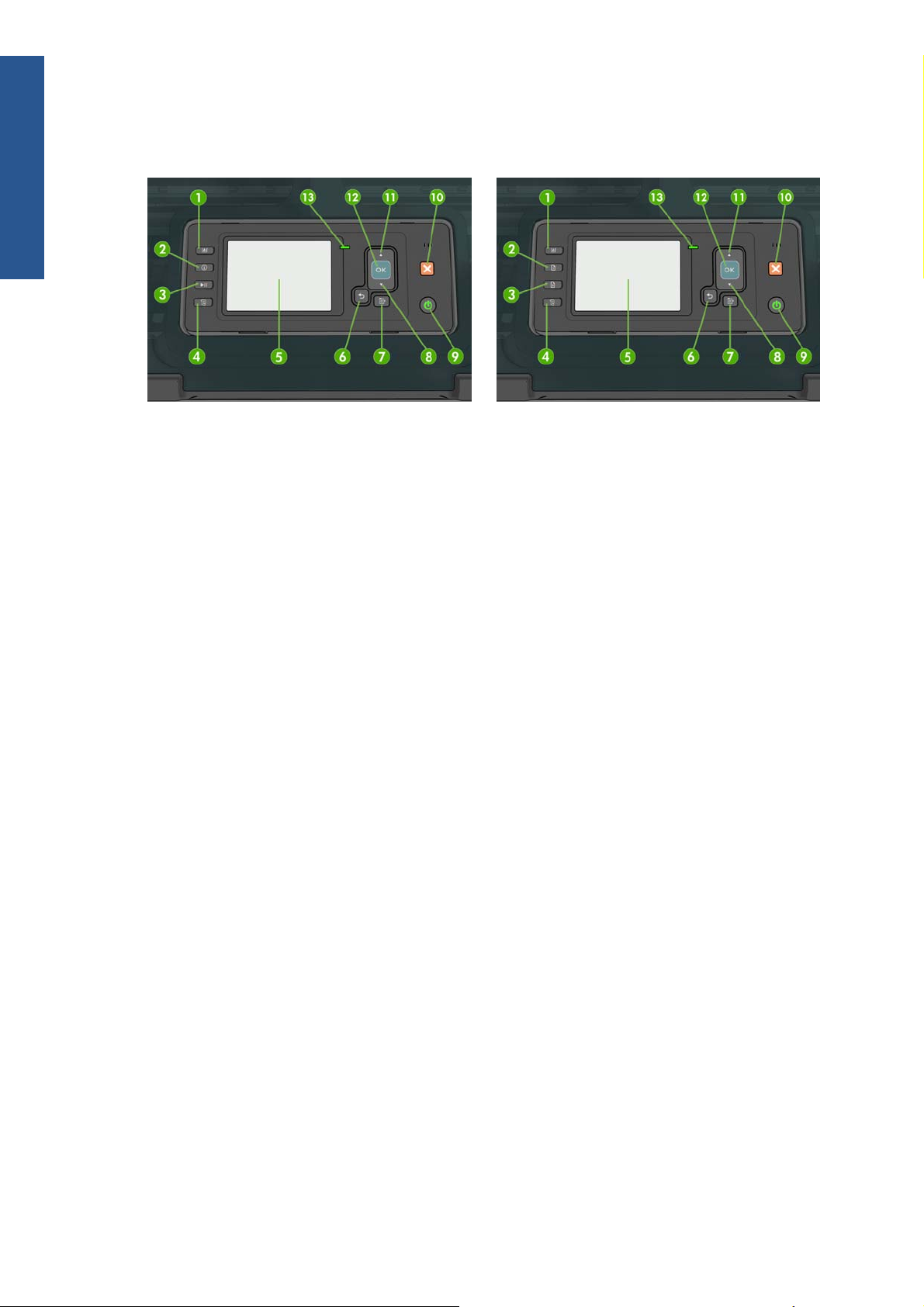
HP Designjet T1200 series HP Designjet T770 series
The front panel has the following components, starting with the four direct-access keys:
1. View ink levels key.
2. View information key. By pressing this key repeatedly, you can see information about all loaded
papers (roll 1, roll 2, sheet) and about the printer's connection to the computer.
3. Pause printing key (T1200 series) pauses printing after finishing the current page. Press the key
again to restart printing. This can be useful, for instance, when you want to change or load a roll.
Unload paper key (T770 series) unloads the currently-loaded paper (roll or sheet).
4. Form feed and cut key.
5. Front-panel display - Displays errors, warnings and information on using your printer.
6. Back key - To go to the previous step in a procedure or interaction. To go to the upper level, or
leave the option in the menu, or when given an option.
7. Menu key - Press to return to the main menu of the front-panel display. If you are already on the
main menu it will display the status screen.
8. Down key - To go down in a menu or option, or to decrease a value, for example when
configuring the front-panel display contrast or the IP address.
9. Power key - To turn the printer off or on, it also has a light to indicate the printer's status. If the
power key light is off the printer is off. If the power key light is blinking green, the printer is
starting up. If the power key light is green on, the printer is on. If the power key light is amber on,
the printer is in standby. If the power key light is blinking amber, the printer needs attention.
10. Cancel key - To abort a procedure or interaction.
11. Up key - To go up in a menu or option, or to increase a value, for example when configuring the
front-panel display contrast or the IP address.
2 Chapter 1 Troubleshooting ENWW
Page 9
12. OK key - To confirm an action while in a procedure or interaction. To enter in a submenu in the
menu. To select a value when given an option. If the status screen is displayed, this key takes you
to the main menu.
13. Status light - Indicates the printer's status. If the Status light is solid green, the printer is ready. If it
is flashing green, the printer is busy. If it is solid amber, there is a system error. If it is flashing
amber, the printer needs attention.
Table 1-1 Service Key Combinations
Label Description
Diagnostic mode With the printer off, press and hold the Up and OK keys.
While holding the Up and OK keys down, press the Power
key to turn on the printer. Wait until the HP logo appears in
the front-panel display, then release all three keys.
Service menu (service engineers only) From the main menu, press and hold the Up and Cancel
keys.
Service menu (for users) From the main menu, press and hold the Down and Cancel
keys.
For a full list of front-panel options and how to reach them, see Front-panel menu maps on page 408.
Troubleshooting
General troubleshooting
This chapter will guide you through the relevant steps to take when troubleshooting the printer.
Troubleshooting system error codes
System Error Codes on page 53 contains a list of system error codes and their respective descriptions
and recommended corrective actions. Try only one recommended action at a time and check whether
the error code has disappeared.
If you have an error code which is not documented in this Service Manual or you have an error which
you cannot resolve, then report the error to the HP Response Center or the nearest HP Support Office.
When reporting the error, have the following information ready:
Model and Serial Number of the printer.
●
Which firmware revision the printer is using (See Note below). Check firmware in Utilities /
●
Statistics / Code rev.
The complete error number (See Note below).
●
The Service Configuration Print.
●
The Current configuration sheet.
●
ENWW
Which software application the customer is using (name, version, etc.).
●
NOTE: When reporting the System Error Code, make sure that you supply the full Error Code and the
firmware version. Without this information, HP Support Personnel cannot help you.
General troubleshooting
3
Page 10

Troubleshooting
Performing a service test on a failed assembly
If possible, always perform a Service Test on the component/assembly that you are about to replace,
just to make sure that is the component/assembly that has failed.
NOTE: If the test on that component/assembly passes, you should not replace it.
For information on the Service Tests and how to use them see
Diagnostics Menu on page 94.
Performing the necessary service calibrations
Is the printer calibrated correctly after replacing a component? For information on the Service
Calibrations and how to use them see
NOTE: Remember that certain Calibrations are required even if an Assembly has been disassembled
to gain access to another Assembly or Component.
Service Menu on page 128.
Solving print-quality problems
Whenever a print-quality problem appears, it is advisable to print the Diagnostic Print to help diagnose
the problem. The Diagnostic Print will help you differentiate between possible printhead errors and
other problems such as incorrect front-panel selection, driver or RIP configuration or mechanical
problems.
The Front Panel is blank
See What to do if the Front Panel is blank on page 55.
The printer does not power on
See What to do if the Front Panel is blank on page 55.
The printer continuously rejects printheads
1. Clean the flex contacts on the Printhead and in the Carriage Assembly using the Carriage
Interconnect Wiper and try again.
2. If all the Printheads are rejected (the status message on the Front Panel does not show "OK" for
all the Printheads) then perform the Electronic Module Test. See
on page 106.
Cover sensors are not working
1. Perform the Sensors Test. See Sensors Test on page 113.
2. Check that the cable for the faulty sensor is not damaged and is connected correctly.
3. Replace the faulty Sensor.
Electronics Module Test
4 Chapter 1 Troubleshooting ENWW
Page 11

The line sensor has problems detecting paper
1. Check the type of paper that is being used since the Line sensor may have problems detecting
transparent paper or some types of Non-HP paper. Try loading white HP paper in to the printer
and check that the Line sensor detects it.
2. The Line Sensor is not calibrated correctly. Perform the Line Sensor Calibration. See
Calibration on page 155.
3. The Line Sensor is damaged or faulty. Replace the Line Sensor. See
Line Sensor on page 296.
Troubleshooting paper jams and printhead crashes
The failure modes "paper jam" and "head crash" are grouped together because in many cases a
paper jam causes the paper to lift up into the Carriage path and cause a Printhead crash, thus causing
many paper jam failures to be reported as head crashes.
1. Did the paper jam occur when loading paper?
If the client has had paper jams, it is common for pieces of paper to get stuck in the paper
●
path. Clear the paper path.
NOTE: When clearing a paper jam, sometimes paper is stuck in the paper path. To clear this,
you must lift the Media Lever and insert thicker paper into the paper path to push out the paper
that is still stuck there.
2. Is the customer using non-HP paper?
The use of non-HP paper can easily be the cause of paper jams and head crashes (especially
●
head crashes because HP paper is specially formulated to avoid cockle, one of the primary
causes of head crashes). If the paper is not HP approved, advise the customer to use HP
paper and check to see whether the problem is now solved.
Line Sensor
Troubleshooting
Banding at variable extreme environmental conditions
Since the Accuracy Calibration has been done at normal environmental conditions, printing in extreme
environmental conditions will cause banding because the advance of the Media Advance Roller does
not correspond to the same conditions that the calibration was done in. To solve the problem, try the
following:
Perform the Accuracy Calibration in the new environmental conditions (Refer to the User’s Guide).
Worm marks on HP Coated paper with light area fills
Light bands (S-shaped) in Paper axis direction where light area fills are printed, causing unacceptable
Image Quality defect.
Print the Service Configuration Print and check whether the humidity level is very low (below 30%).
●
Increasing humidity may help in reducing the severity of the problem.
NOTE: The paper is causing the problem and not the printer. Do not attempt to try to replace printer
parts to solve this problem.
ENWW
General troubleshooting
5
Page 12

Troubleshooting
The basket was damaged during printer setup
1. There are three plastic parts that could break during printer installation and need replacing.
2. Check the parts table and graphics in Parts and Diagrams to identify what service parts you must
order. See
Printer Support on page 161.
3. Replace the component. See
Bin Assembly on page 188.
Paper-handling troubleshooting
Roll paper The Front Panel indicates that paper is misaligned or incorrectly positioned
The roll may be loaded the wrong way. The paper should load over the roll toward you.
●
Check that the paper is correctly loaded onto the spindle.
●
The paper may be loaded at an angle. The right-hand edge must be aligned with the blue line on the
●
Print Platen.
Check that the Right Roll Support is properly attached and screwed to the printer.
●
The Rewinder, located on the Right Roll Support, should maintain proper back tension. If the Right Roll
Support is misaligned or not properly attached to the printer, the Rewinder will not function properly.
To further diagnose problems with the Rewinder, see
Sheet paper
The sheet must be loaded with the right-hand edge against the white line on the upper roll cover.
●
The paper may be crumpled or warped or may have irregular edges.
●
If hand-cut paper is used, the edges may not form a right-angle or they may be rough. If possible,
●
hand-cut paper should not be used. Only purchased sheet paper should be used in the printer.
Rewinder Test on page 114.
If you have problems with paper jams, check that the Overdrive is not obstructed by bits of paper or
●
using the Turn Drive Roller Service Utility. See
Check that the Right Roll Support is properly attached and screwed to the printer.
The Rewinder, located on the Right Roll Support, should maintain proper back tension. If the Right Roll
Support is misaligned or not properly attached to the printer, the Rewinder will not function properly.
To further diagnose problems with the Rewinder, See
Print-quality troubleshooting
Print-quality troubleshooting actions
NOTE: For some print-quality problems, a Call Agent can try to troubleshoot the printer by requesting
the Customer to perform certain actions. Using this process, most problems can resolved without the
need of an on-site visit.
Use the Print Quality Troubleshooting Wizard to help customers with their print quality or color
problems. For information about how to use the Print Quality Troubleshooting Wizard, see
Troubleshooting Wizard on page 30.
Turn Drive Roller on page 130.
Rewinder Test on page 114.
Print Quality
6 Chapter 1 Troubleshooting ENWW
Page 13

When faced with a Print Quality problem, perform the following actions in order to resolve the
problem:
1. Printer Configuration:
Check that the paper type loaded corresponds to the paper type selected in the front panel
●
and in the software. You can check the paper type selected by pressing the View
information key on the Front Panel.
Make sure that the correct Print Quality settings are used for different types of print content.
●
See
Print-quality troubleshooting actions on page 6 for further information.
Dry time should be set to “Optimal”.
●
2. Perform Printhead recovery (Main Menu/Image Quality Maintenance/Clean Printheads).
3. Paper:
Select the correct paper type through the front panel when loading it.
●
Make sure that HP or HP-approved paper is being used.
●
4. Perform the Printhead Alignment (Main Menu/Image Quality Maintenance/Align Printheads),
using the same paper type with which you were experiencing unacceptable image quality, if
feasible (some paper types are not suitable for Printhead Alignment).
Troubleshooting
5. Check whether the latest version of the firmware is installed. If not, install the latest firmware
revision.
The Service Image Quality Diagnostic Print
What is the Service Image Quality Diagnostic Print?
The printer contains an internal Image Quality Test which helps you to diagnose the possible source of
any image quality defects. The Service IQ Diagnostic Print is available in the following options:
1. Image Quality Service Best Plot. This plot helps you to diagnose in more detail the possible source
of any image quality defects. It is accessible through the Service Utility Menu.
The Image Quality Service Best Plot uses the Best Print Mode and is divided in to three parts as
follows:
Diagnostic Part 1: Printhead Reliability Test. The purpose of this test is to identify which
●
Printhead is faulty.
Diagnostic Part 2: Printhead Alignment Test. This test is designed to check any color-to-color
●
and bi-directional misalignment the printer may have.
Diagnostic Part 3: Printheads and Paper Advance test. This test is designed to check whether
●
the Printheads and the Media Advance Mechanism are working correctly.
ENWW
2. Image Quality Service Normal Plot. This plot is the same as the Image Quality Service Best Plot but
uses the Normal Print Mode.
3. Advanced Diagnostic Plot. These tests provide more information of the IQ defects that we could
find in the Image Quality Service plot. For more information, see
on page 12.
The Advanced Diagnostic Prints
Print-quality troubleshooting
7
Page 14
Troubleshooting
Considerations for Printing the Diagnostic Print
1. The IQ Diagnostic Print prints in A3 and B sizes so you must have paper loaded (roll or sheet) that
2. Use the same type of paper that the customer was using when they found the image quality
3. If the customer is using non-HP paper and after the Image Quality Test you still have the same
Printing the Diagnostic Print
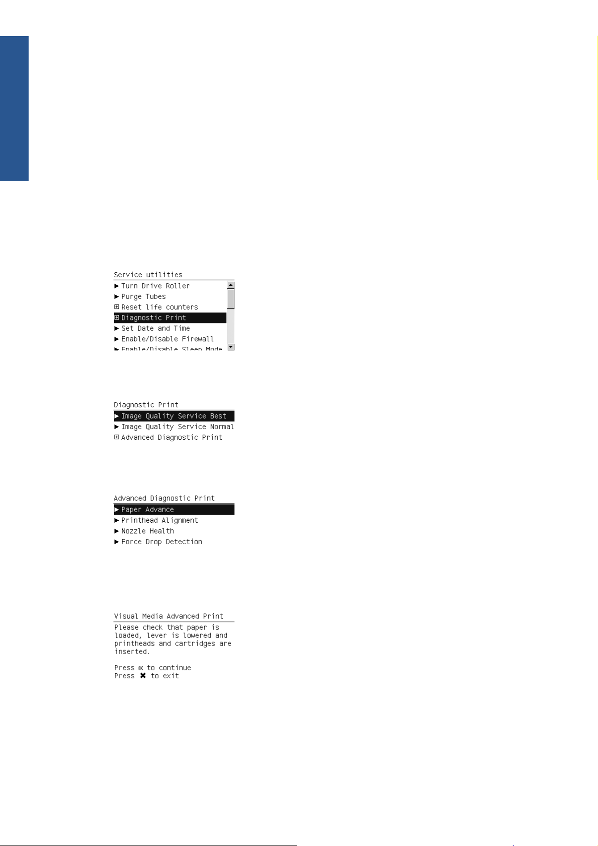
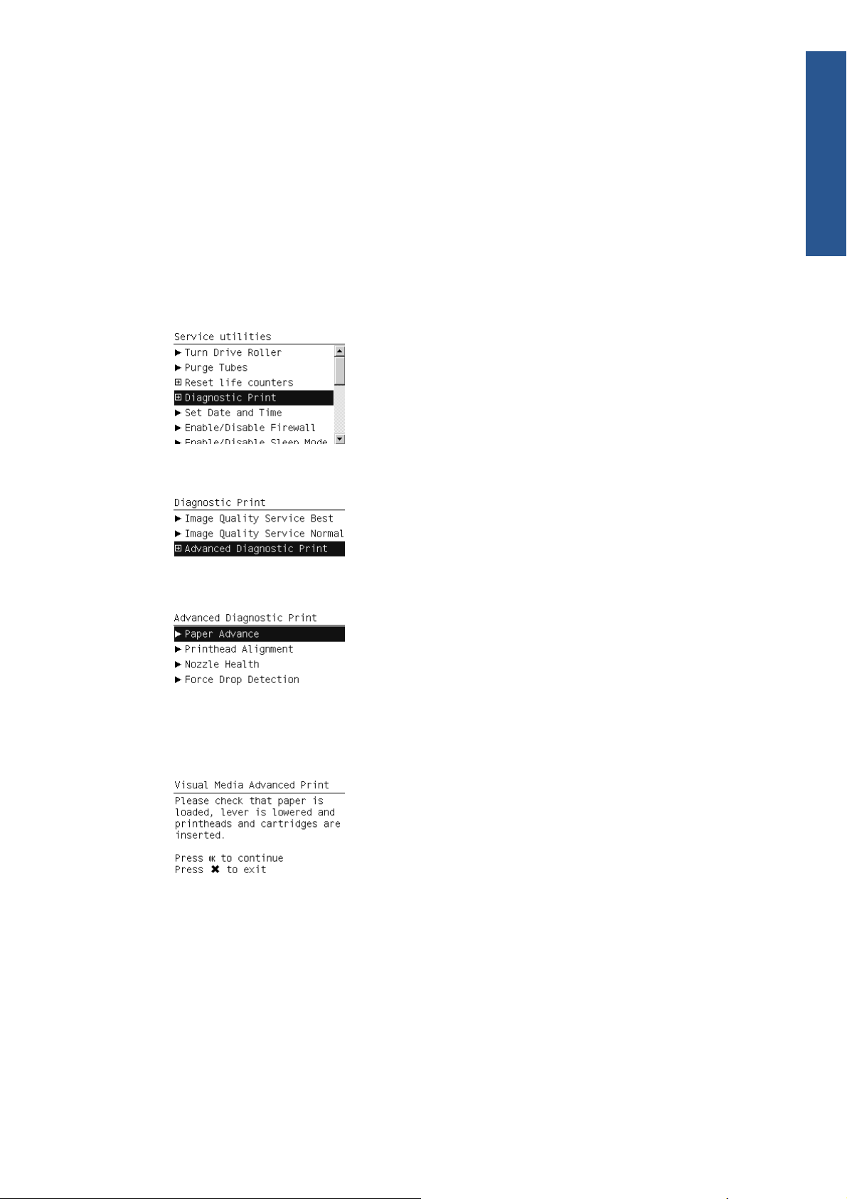
1. In the Service Utilities submenu, scroll to “Diagnostic Print” and press OK.
is this size or larger.
problem.
image quality problems, change to genuine HP paper and repeat the Image Quality Test.
If you do see problems with the Image Quality Test, continue with the Advanced Diagnostic
procedures which will help you diagnose the problem.
2. You will be given three options. Use the Arrow keys to make the selection and press the OK key
to start printing the required Diagnostic Print or to enter the Advanced Diagnostics menu.
3. If you selected Advanced Diagnostics Print in the previous step, use the Arrow keys to make
the required selection,and press the Enter key to start printing.
4. Make sure paper is loaded, the Media Lever is lowered and that the Ink System is correctly
installed. Press the OK key to print the Diagnostic Print or press Cancel to exit without printing the
Diagnostic Print.
5. The selected Diagnostic Print will now be printed.
Reading the Diagnostic Print results
Diagnostic Part 1: Printhead Reliability
8 Chapter 1 Troubleshooting ENWW
Page 15
The Nozzle Print Test test is designed to check that the Printhead nozzles print correctly.
The nozzles check (top of the plot) is printed in a one-pass full swath mode. The diagnostics test prints
out every single nozzle of each Printhead without applying an error hiding or alignment algorithm.
For each Printhead, you can see both the adjacent and the consecutive nozzles.
If any nozzles are not printing correctly they will be shown on the right of each Printhead Nozzle test.
There is a series of numbered stepped diagonal lines. If one or more of the nozzles are clogged,
malfunctioning or mis-positioned, you will see that the stepped lines are broken or misdirected in one or
more places.
Troubleshooting
Below, the stepped lines highlighted in yellow are broken. When the line is completely broken, this
means the nozzle is out.
Below, the stepped lines highlighted in yellow are misdirected. When the line is misdirected, this means
the nozzle is malfunctioning or out of position.
On the left of each Printhead Nozzle test, there is a series of horizontal straight lines. If one or more
nozzles are misdirected there will be unequal spaces between the corresponding lines.
Corrective action
If the printer has nozzle defects, you can still get perfect print quality results. The printer can
automatically compensate for nozzle defects, so there is no need to replace the Printhead.
ENWW
Print-quality troubleshooting
9
Page 16
Troubleshooting
The method of improving Nozzle Defects is to:
1. Recover the Printheads, using the Front Panel Main Menu/Image Quality Maintenance/Clean
2. Reprint the Printhead Nozzles Test Plot to check that the defective nozzles have been corrected.
3. If the problem continues, replace the defective Printhead.
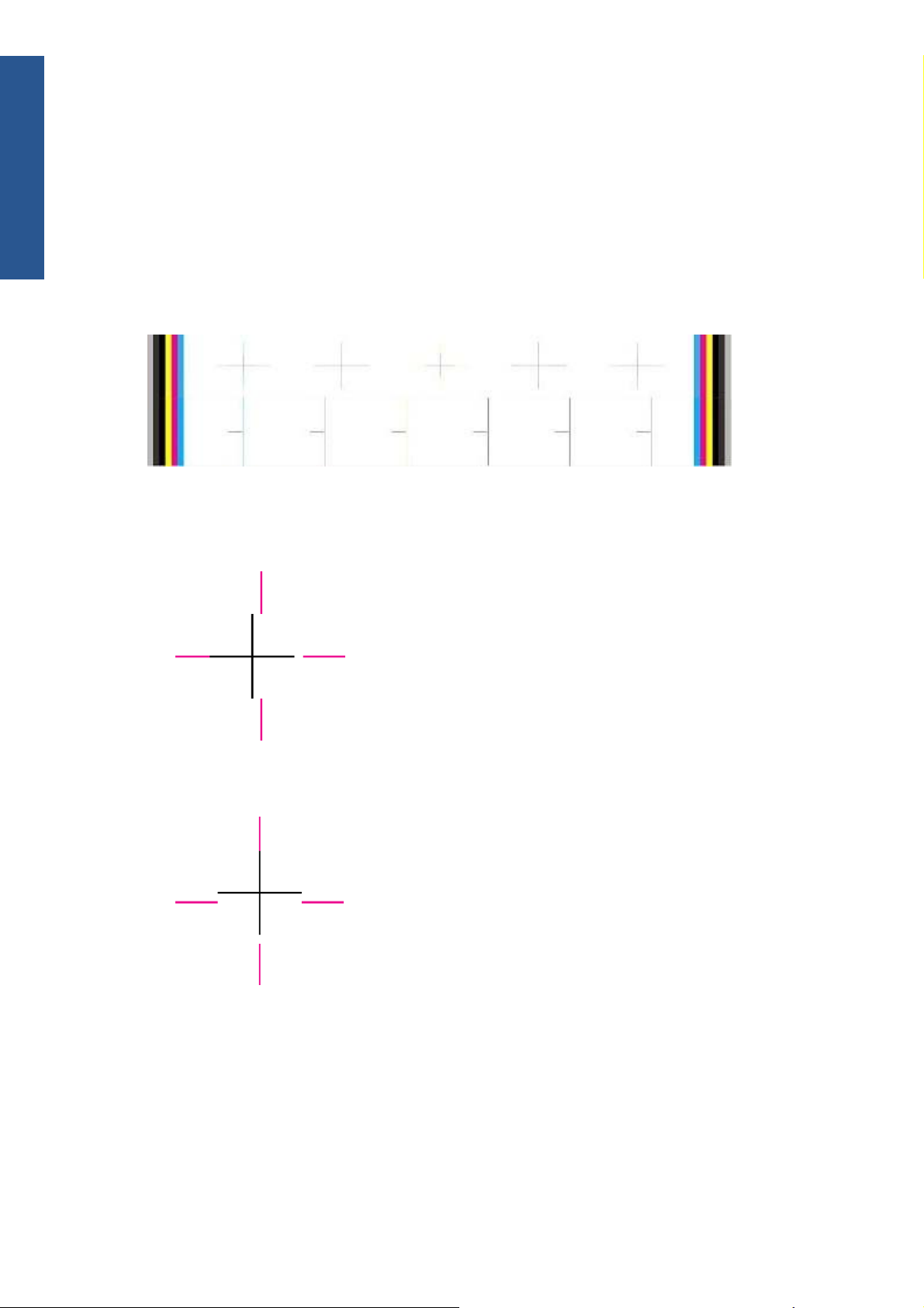
Diagnostic Part 2: Printhead Alignment
This test is designed to check any color-to-color and bi-directional misalignment the printer may have.
1. If the printer is experiencing horizontal misalignment problems, the Alignment Test will show
Printheads option.
something like this:
2. If the printer is experiencing vertical misalignment problems, the Alignment Test will show
something like this:
10 Chapter 1 Troubleshooting ENWW
Page 17

3. If the printer is experiencing bi-directional misalignment problems, the Alignment Test will show
something like this:
Corrective action
Perform the Printhead Alignment (Main Menu/Image Quality Maintenance/Align Printheads), using the
same paper type with which you were experiencing unacceptable image quality, if feasible (some
paper types are not suitable for Printhead Alignment).
Diagnostic Part 3: Printheads & Paper Advance
This test is designed to check whether the Printheads and the Paper Advance Mechanism are working
correctly. This part of the Image Quality Test should not be used to check for color consistency or
accuracy.
Troubleshooting
Banding
If the printer is experiencing a banding problem, you will see repetitive horizontal bands within the
printed image.
Darker horizontal bands or lines repeated along the vertical band (from top to bottom at the same
●
distance).
Whiter horizontal bands or lines along the vertical band (from top to bottom at the same distance).
●
The plot is printed in Best or Normal mode (according to the menu option selected) with Error Hiding
ON. The top band has 100% ink density patches while the bottom band has 50% ink density patches.
ENWW
Print-quality troubleshooting
11
Page 18

Troubleshooting
Troubleshooting Banding Problems
If banding does not occur in all the colors, then it is more than likely a Printhead problem. In this
case, try the following:
1. Check that the appropriate print quality settings are being used (refer to the User’s Guide for more
2. Recover the printheads using the option through the Front Panel (Main Menu/Image Quality
Corrective action
In order to solve problems that result in banding, try the following
information).
Maintenance/Clean Printheads). Reprint the Diagnostic Print or the print file and if the problem
persists, replace the faulty Printhead.
If banding does occur in all the colors, then it is more than likely a Paper Advance problem:
If the bands are light, it means that the paper has advanced too much.
●
If the bands are dark, it means that the paper hasn’t advanced enough.
●
In high quality modes, graininess in all colors can indicate problems either with alignment or
●
Paper Advance.
1. Check that the appropriate print quality settings are being used (refer to the User’s Guide for more
information).
2. Check that the loaded paper is the same type as selected in the printer. You can check the paper
type selected through the Front Panel (Main Menu/Paper menu/View loaded paper).
3. If the customer is using low-quality paper, try recommending better-quality paper (preferably HP
paper). Printer performance can only be guaranteed by using recommended papers.
4. Perform Paper Advance Calibration using the same type of paper that will be used for the final
print (Main Menu/Image Quality Maintenance/Paper Advance Calibration/Calibrate Paper
Advance).
If there is white point banding in only one color band and the problem cannot be fixed using the
Printhead recoveries, in some cases using the Force Drop Detection option can fix this issue.
No Printing Defects Found in the Diagnostic Print
If all the test patterns from the Diagnostic Print are correct and you still experience Image Quality
problems, you can use the following procedures to resolve the problem.
Reading the Advanced Diagnostic Print Results
●
Printhead Alignment
●
Nozzle Health
●
Force Drop Detection
●
The Advanced Diagnostic Prints
What are the Advanced Diagnostic Prints?
These tests provide more information about the IQ defects found in the Image Quality Service plot.
12 Chapter 1 Troubleshooting ENWW
Page 19
The Advanced Diagnostic Print is divided into the following parts:
Visual Media Advanced Diagnostic. Used to check advance reliability.
●
Printhead Alignment Diagnostic. Used to check pen alignment reliability.
●
Visual Nozzle health Diagnostic. Used to check nozzle health reliability.
●
Force Drop Detection. Used to reset the nozzle health historic database and force new drop
●
detection.
Printing the Advanced Diagnostics Print
1. In the Service Utilities submenu, scroll to “Diagnostic Print” and press OK.
2. You will be given three options. Use the Arrow keys to select Advanced Diagnostic Print.
Troubleshooting
3. Use the Arrow keys to select the option you want, and press the OK key to start printing.
4. Make sure paper is loaded, the Media Lever is lowered and that the Ink System is correctly
installed. Press the OK key to print the Diagnostic Print or press Cancel to exit without printing the
Diagnostic Print.
5. The selected Advanced Diagnostic Print will now be printed and, if necessary, automatically
scanned.
Reading the Advanced Diagnostic Print results
ENWW
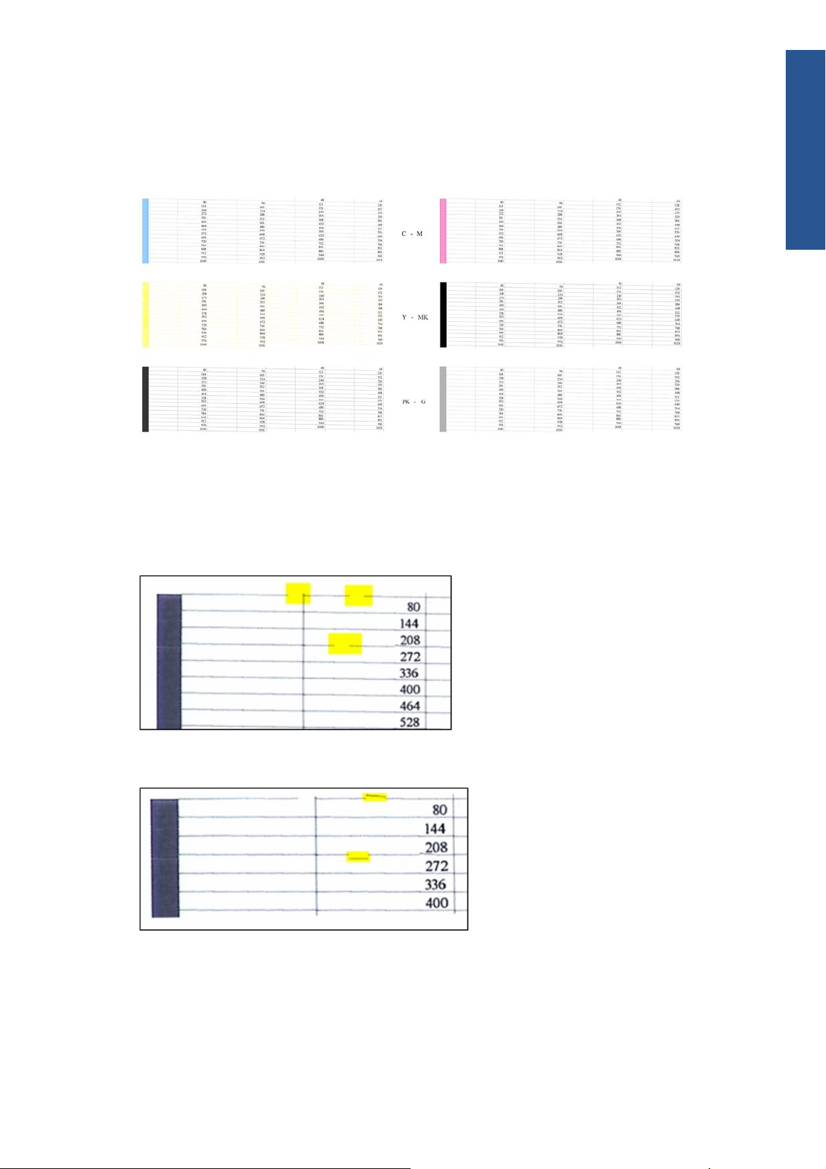
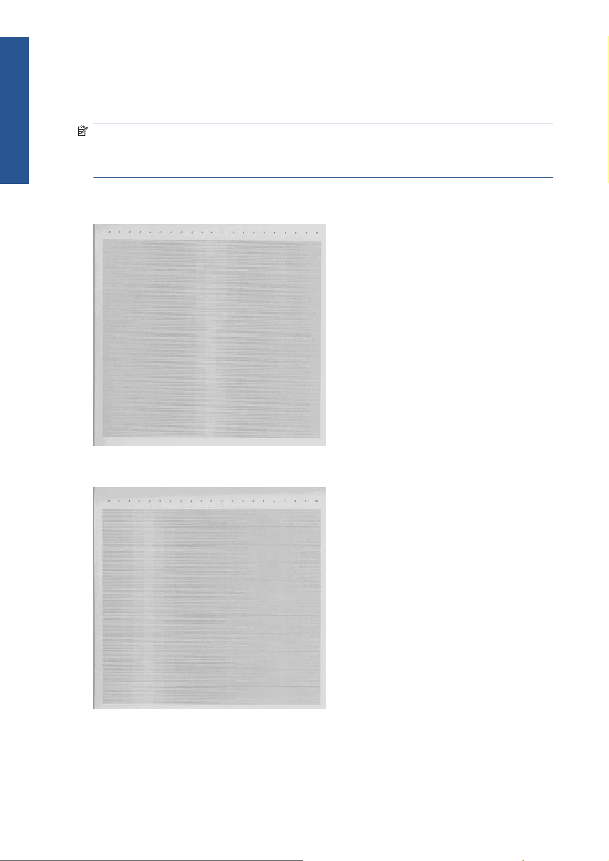
Paper Advance
This plot helps you to visually check any alignment problems of the printer. You use it to precisely
measure the paper advance error with a one dot row accuracy, and to check the stability of the paper
advance.
Print-quality troubleshooting
13
Page 20
Troubleshooting
The whitest vertical line should be positioned in the 0 offset column with minor variations between +2
and -2 columns. If the offset is not positioned on the 0 column or between +2 and -2 columns and the
whitest vertical varies greatly, the printer requires Paper Advance Calibration (Main Menu/Image
Quality Maintenance/Paper Advance Calibration/Calibrate Paper Advance).
NOTE: It is very important to check that the loaded paper is the same paper type as selected in the
front panel. You can check the paper type selected through the Front Panel (Main Menu/Paper menu/
View loaded paper). The wrong type of paper selected will produce an offset error in the Paper
Advance.
The following plot shows correct paper advance, there is a straight white line positioned close to the 0
column for the majority of the points.
The following plot shows a bad paper advance, there is a straight white line positioned close to the -6
column, instead of the 0 column for the majority of the points.
14 Chapter 1 Troubleshooting ENWW
Page 21

Corrective action
To fix Paper Advance problems, try the following:
1. Check the Paper Advance Calibration Status. This can be done by going to Main Menu/Paper/
View Loaded Paper. At the bottom, the Front Panel displays the Paper Advance Calibration status.
There are three status messages:
DEFAULT. The paper loaded is recognized as HP paper, which is already optimized and
●
calibrated for the printer. Do not calibrate the Paper Advance for this paper.
RECOMMENDED. The paper loaded is not recognized as HP paper, and Paper Advance
●
values have not been customized for this paper type. In this case, calibrate the Paper
Advance from the user menu.
OK. This indicates that the paper loaded has been calibrated before. If the printer continues
●
to have banding and graininess problems, calibrate the Paper Advance from the user menu.
NOTE: Whenever the printer's firmware is upgraded, the paper advance calibration values
will be reset to factory default.
2. To calibrate the Paper Advance from the user menu, go to Main Menu/Image Quality
Maintenance/Paper Advance Calibration/Calibrate Paper Advance.
NOTE: It is very important to check that the loaded paper is the same paper type as selected in
the front panel. You can check the paper type selected through the Front Panel (Main Menu/Paper
menu/View loaded paper). The wrong type of paper selected will produce an offset error in the
Paper Advance.
NOTE: Some paper types are not suitable for Paper Advance Calibration. Do not use colored
papers or transparent materials such as translucent bond, clear film, matte film, tracing paper, or
vellum.
Troubleshooting
Paper Advance calibration from the user menu will only calibrate the Paper Advance for the paper
type loaded in the printer at that moment.
3. If Calibrate Paper Advance has mostly solved the problem, try Adjust Paper Advance to fine tune
the Paper Advance (Main Menu/Image Quality Maintenance/Paper Advance Calibration/
Adjust Paper Advance).
Select the percentage of change from -100% to 100%. To correct light banding, decrease the
percentage. To correct dark banding, increase the percentage.
4. The Paper Advance calibration from the service menu will calibrate the Paper Advance for all
paper types. This action is recommended when:
The Paper Advance calibration from the user menu does not solve the problem.
●
The Paper Advance problems affect all paper types.
●
The procedure for Paper Advance Calibration from the service menu is documented in Chapter 5,
Service Calibrations. See
Printhead Alignment
NOTE: To ensure you obtain meaningful results, use the same type of paper that the customer was
using when they encountered the image quality problem.
Paper Advance Calibration on page 148.
ENWW
Print-quality troubleshooting
15
Page 22
Troubleshooting
This plot helps you to visually check any alignment problems of the printer. You use it to precisely
measure the alignment error with a 3 dot row accuracy. For the printer to be considered correctly
aligned, the results must be within ±3 dot row.
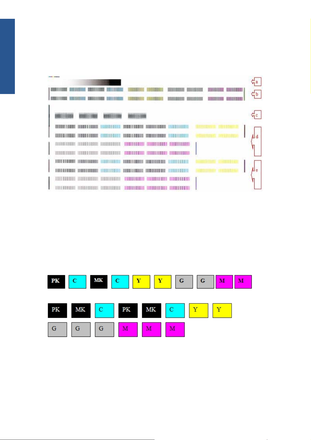
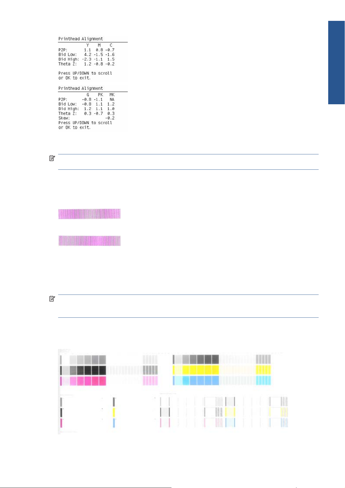
The illustration shows the complete Printhead Alignment that identifies each of the specific alignment test
results covered.
The Printhead Alignment Diagnostic print shows the following diagnostic test results:
a Line Sensor Calibration
b Pen to Pen Align
c Carriage thetaZ
d Bidirectional align (high
e Bidirectional align (Low)
For tests a, b, and c, the order of the color band is:
For tests e and f, the order of the color band is:
Once the printer has correctly printed and scanned the Printhead Alignment Diagnostic print, the Front
Panel displays the results. The top row displays the printhead, and the left column displays the test.
The results are separated onto two screens. Use the Arrow keys to display the second results screen.
16 Chapter 1 Troubleshooting ENWW
Page 23
Any printhead with a test result containing a number that is not within the ±3 dot row range is
misaligned.
NOTE: The mK printhead is used as a reference to test the other printheads. If all the printheads fail
the Pen to Pen tests, it is the mK printhead that is misaligned.
Reading the Printhead Alignment Diagnostic Print
The following plot shows correct printhead alignment for all patterns. The clear band is in the center of
the pattern.
The following plot shows bad printhead alignment. The clear band is not in the center of the pattern.
Corrective action
Troubleshooting
If any of the printheads are misaligned beyond the ±3 dot row range, perform a Printhead
●
Alignment.
If a Printhead Alignment does not correct the problem, replace the bad printhead.
●
NOTE: If the customer is using non-HP paper and after the Image Quality Test you still have the same
image quality problems, change to genuine HP paper and repeat the Image Quality Test. The best
alignment calibration is obtained using HP Photo Paper.
Nozzle Health
The print contains three separate parts.
ENWW
Print-quality troubleshooting
17
Page 24

Troubleshooting
a The Variable Frequency Nozzle health plot with odd/even nozzles separation. This is used to detect
misdirected nozzles, weak nozzles, or nozzles not working correctly at all frequencies.
b Inspector measuring tool test plot.
NOTE: Test b should not be used by Service Engineers.
c Nozzle Print Test which is also part of the Image Quality Service Plot. This test is designed to
check that the Printhead nozzles print correctly. The test prints out every single nozzle of each
Printhead. No error hiding or Printhead Alignment algorithm is applied. For each Printhead, you can
see both the adjacent and the consecutive nozzles.
This is what you would see in the Nozzle Print Test part if there are nozzles not printing correctly:
1. On the right of each Printhead Nozzle test, there is a series of numbered stepped diagonal lines.
2. On the left of each Printhead Nozzle test, there is a series of horizontal straight lines. If one or
Corrective action for Nozzle Defects
If the printer has nozzle defects, it does not mean that you will not get perfect print quality results. The
printer has automatic procedures to hide many nozzle defects.
If one or more of the nozzles are malfunctioning or mis-positioned, you will see that the stepped
lines are broken or misdirected in one or more places.
more nozzles are misdirected there will be unequal spaces between the corresponding lines.
1. Recover the Printheads using the option through the Front Panel (Main menu/Image quality
maintenance/clean printheads).
2. Reprint the Nozzle Print test to check that the defective nozzles have been corrected.
3. If the problem continues, replace the defective Printhead.
Force Drop Detection
If the Nozzle Print Test plot has persistent white point banding in only one color that cannot be fixed
with a printhead recovery, you can use this option to resolve the problem by resetting the nozzle health
database so that all nozzles are assumed to be correct.
Once the nozzle health database has been reset, drop detection is forced.
The normal cause of this white point banding in a single color is the incorrect detection of failed
nozzles by the drop detector.
Perform the test as follows.
1. Select Advanced Diagnostic Print.
2. Select Force Drop Detection.
18 Chapter 1 Troubleshooting ENWW
Page 25
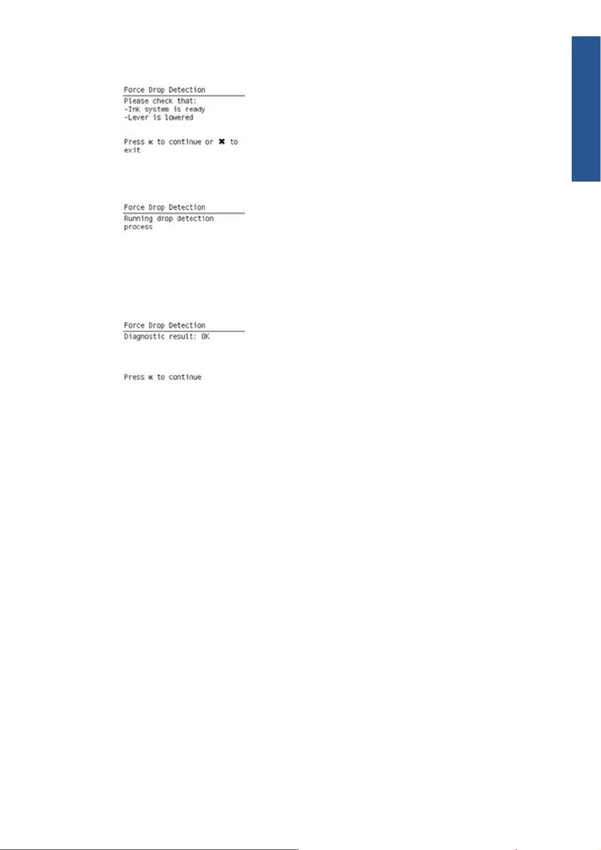
3. Make sure the Media Lever is lowered and the ink system ready, then press OK.
4. The printer runs the drop detection.
5. Press OK to end the test and return to the menu.
Troubleshooting
Troubleshooting print-quality problems
General advice
1. To achieve the best performance from the printer, only genuine HP accessories and supplies
should be used.
2. Make sure that the paper type selected in the Front Panel is the same as the paper type loaded
into the printer.
3. Make sure to use the most appropriate print quality settings for your purposes. A lower print
quality is likely to be seen if the print quality slider has been moved to the Speed end of the
scale, or the custom quality level set to Fast.
4. Check that the environmental conditions (temperature, humidity) are within the temperature/
humidity range as specified for the printer (refer to the User’s Guide for more information).
5. Check that the ink cartridges and printheads have not exceeded their expiration dates.
Horizontal lines across the image (banding)
When you look at the image you have printed, there are horizontal lines across the print. Here are two
examples of what you might see if you have this problem:
ENWW
Print-quality troubleshooting
19
Page 26

Troubleshooting
Corrective action
1. Check that the paper type loaded corresponds to the paper type selected in the front panel and in
2. Check that the appropriate print quality settings are being used (refer to the User’s Guide for more
3. Print the Service Image Diagnostics Print, and clean any printheads that need cleaning. Reprint the
the software. You can check the paper type selected by pressing the View information key on
the Front Panel.
information) and reprint the image. In some cases print quality problems can be resolved by
selecting a higher print quality level.
job in case the problem has been solved.
4. Check the paper advance calibration status. If the status is PENDING, calibrate the paper
advance: at the Front Panel, select the Image Quality Maintenance icon, then Paper advance
calibration > Calibrate paper advance.
5. After calibration, reprint the job.
6. Try again with a new roll of paper.
7. Watch the printer carriage when it reaches the end of its swath. If there is an unexpected delay,
this may cause the banding.
If this is the case, the following corrective measures can be taken:
Do not use the computer while printing. Close applications that use a large amount of
●
computer resources.
Convert the file to PDF. Formats like PDF require less resources to print, which may solve your
●
banding problem.
This delay is possibly the result of the following:
The user is performing tasks with other applications while printing (particularly image
●
processing applications). These applications are using too many computer resources, and the
computer cannot effectively process the print job.
The file to be printed is complex, and the computer does not have the capacity to print such
●
complex files.
If printing over a LAN, it is possible that the LAN is too slow to meet the requirements of the
●
print job.
20 Chapter 1 Troubleshooting ENWW
Page 27
Lines are missing, too thin, or too thick
Shown below is an example of what you might see if you have this problem:
Corrective action
1. Check that the paper type loaded corresponds to the paper type selected in the front panel and in
the software. You can check the paper type selected by pressing the View information key on
the Front Panel.
2. Check that the appropriate print quality settings are being used (refer to the User’s Guide for more
information). Select the custom print quality options in the Print dialog, and if you are using best
quality and glossy paper, try turning on the Maximum detail option. Reprint the job in case the
problem has been solved.
Troubleshooting
3. If the resolution of the image is greater than the printing resolution, a loss of line quality may be
seen. You can find the Max. Application Resolution option in the Windows driver dialog's
Advanced tab, under Document Options > Printer Features. Reprint the job in case the problem
has been solved.
4. Check the Printhead alignment status. If the status is PENDING, perform the Printhead Alignment
(Main Menu/Image Quality Maintenance/Align Printheads). After alignment reprint the job.
5. Check the paper advance calibration status. If the status is PENDING, calibrate the paper
advance: at the Front Panel, select the Image Quality Maintenance icon, then Paper advance
calibration > Calibrate paper advance. After calibration, reprint the job.
6. Use Part 3 of the Image Quality Diagnostic Print, check if there are a significant amount of nozzles
out in the color that is actually causing the problem (if see you a problem with the Black color
in the customer print, then only check the Black printhead in the Image Quality Diagnostic Print). If
there is a significant amount of nozzles out then replace the defective Printhead.
Problems with stepped lines
When you look at the image you have printed there are 'stepped lines' in the borders of arrows and
diagonal lines. The lines should be straight with no stepping.
Shown below is an example of what you might see if you have problems with Stepped Lines:
ENWW
Print-quality troubleshooting
21
Page 28

Troubleshooting
Corrective action
1. The problems may be inherent in the image that you are trying to print. Try to improve the image
2. Check that the appropriate print quality settings are being used (refer to the User’s Guide for more
3. Select the custom print quality options in your Print dialog, and if you are using Glossy paper and
with the application that generated the file.
information).
BEST quality, turn on the Maximum Detail option.
4. Change the image rendering resolution to 300 dpi (only in EconoMode Printmode) or 600 dpi
depending on the printing needs. You can find the Max. Application Resolution option in the
Windows driver dialog's Advanced tab, under Document Options > Printer Features.
Lines are printed double or in wrong colors
This problem can have various visible symptoms, as shown below:
Corrective action
Reseat the printheads by removing them and then reinserting them.
▲
NOTE: As you reseat the printheads, the printer will automatically align the printheads. It is
important that the alignment is completed properly.
Lines are discontinuous
If the lines are broken in the following way:
22 Chapter 1 Troubleshooting ENWW
Page 29

1. Check that the appropriate print quality settings are being used (refer to the User’s Guide for more
information).
2. Reseat the printheads by removing them and then reinserting them.
NOTE: As you reseat the printheads, the printer will automatically align the printheads. It is
important that the alignment is completed properly.
Lines are blurred (ink bleeds from lines)
This problem is often caused by the ink soaking into the paper, making the lines blurred and fuzzy. This
could be because of the humidity in the air.
Troubleshooting
Corrective action
1. Check that the environmental conditions (temperature, humidity) are suitable for high-quality
printing.
2. Make sure that the paper type selected in the Front Panel is the same as the paper type loaded
into the printer.
3. Try using a heavier paper type. When printing dense colors, it is recommended to use HP
Heavyweight Coated Paper or HP Super Heavyweight Coated Paper.
4. If glossy paper is being used, try changing to a different type of glossy paper.
5. Align the printheads. See
6. Try rotating the image.
ENWW
Image Quality Maintenance Procedure on page 43.
Print-quality troubleshooting
23
Page 30

Troubleshooting
Problems with graininess
Shown below is an example of what you might see if you have problems with graininess:
Corrective action
1. Check that the paper type loaded corresponds to the paper type selected in the front panel and in
2. Check that printing is on the correct side of the paper.
the software. You can check the paper type selected by pressing the View information key on
the Front Panel.
3. Check that the appropriate print-quality settings are being used (refer to the User’s Guide for more
information). In many cases, you can correct grainy printing by raising the print-quality level.
Reprint the job in case the problem has been solved.
4. Reseat the printheads by removing and then reinserting them.
NOTE: As you reseat the printheads, the printer will automatically align them. It is important that
the alignment is completed properly.
5. Check the paper advance calibration status. If the status is PENDING, calibrate the paper
advance: at the Front Panel, select the Image Quality Maintenance icon, then Paper advance
calibration > Calibrate paper advance.
6. After paper advance calibration, reprint the job.
7. If there is only a strip of grain at the top of the job, try leaving a white margin of 5 cm before the
job, or load a new roll of paper (with less paper curl).
Paper is not flat
If the paper does not lie flat when it comes out of the printer, but has shallow waves in it, you are likely
to see visible defects in the printed image, such as vertical stripes. This can happen when you use thin
paper that becomes saturated with ink.
Shown below is an example of what you might see if you have problems with the paper not being flat:
24 Chapter 1 Troubleshooting ENWW
Page 31

Corrective action
1. Check that the paper type loaded corresponds to the paper type selected in the front panel and in
the software. You can check the paper type selected by pressing the View information key on
the Front Panel.
2. Try using a heavier paper type. When printing dense colors, it is recommended to use HP
Heavyweight Coated Paper or HP Super Heavyweight Coated Paper.
Ink marks on the paper
This problem may occur for different reasons.
Horizontal smears on the front of coated paper
If a lot of ink is used on plain or coated paper, the paper absorbs the ink quickly and expands. As the
printheads move over the paper, the printheads may come into contact with the paper and smear the
printed image. This problem is normally seen only on cut sheets of paper (not on roll paper).
Troubleshooting
Corrective action
1. Check that the paper type loaded corresponds to the paper type selected in the front panel and in
the software. You can check the paper type selected by pressing the View information key on
the Front Panel.
2. Use a recommended paper type and the correct print settings.
3. If using sheet paper, try rotating the sheet 90 degrees. The orientation of the paper fibers may
affect performance.
ENWW
Print-quality troubleshooting
25
Page 32

Troubleshooting
4. Try using a heavier paper type. When printing dense colors, it is recommended to use HP
5. Try to increase the margins by relocating the image to the center of the page with the software
Ink marks on the back of the paper
This can happen after a lot of border less printing, especially with non-standard paper sizes. Ink
residues on the platen are likely to mark the back of the paper.
Corrective action
●
Problems with the edges of objects
Stepped or not sharp
The edges of objects or lines appear to be poorly defined or lighter in density than expected.
Heavyweight Coated Paper or HP Super Heavyweight Coated Paper.
application being used.
Clean the platen with a soft cloth. Clean each rib separately without touching the foam between
the ribs.
Corrective action
If the print quality slider has already been set to Quality in the Print dialog, select the custom
●
print quality options, and try setting the quality level to Normal (refer to the User’s Guide for
more information).
Darker than expected
The edges of objects seem darker than expected.
26 Chapter 1 Troubleshooting ENWW
Page 33

Corrective action
If the print quality slider has already been set to Quality in the Print dialog, select the custom
●
print quality options, and try setting the quality level to Normal.
Black and white prints do not look neutral
Consider printing in grayscale (color options submenu inside the printing preference menu). See the
User's Guide for more information.
Horizontal lines at the end of a cut sheet print
There is a type of defect that only affects the end of a print, within approximately 30 mm of the trailing
edge of the paper. Some very thin horizontal lines may be seen across the print.
Corrective action
1. Print the Service Image Diagnostics Print, and clean any printheads that need cleaning. Reprint the
job in case the problem has been solved.
2. Try printing with roll paper.
3. Try using larger margins around the image.
Vertical lines of different colors
The print has vertical bands of different colors along it.
Corrective action
1. Try using a heavier paper type. When printing dense colors, it is recommended to use HP
Heavyweight Coated Paper or HP Super Heavyweight Coated Paper.
Troubleshooting
2. Use higher print quality settings (refer to the User’s Guide for more information).
Vertical marks on the print (T1200 series only)
The print has vertical marks caused by the roll cover arm pinches. These marks may be particularly
visible in prints with black area fills on some types of glossy papers.
Corrective action
1. Try using a different glossy paper.
2. Load the roll on the upper spindle and disable the roll cover (only the upper roll cover can be
disabled). See
Disable Upper Roll Cover (T1200 series only) on page 144.
White spots on the print
White spots are seen on the print. This is probably due to paper fibers, dust, or loose coating material.
Corrective action
1. Clean the paper manually with a brush before printing, to remove any loose fibers or particles.
2. Always keep the cover of the printer closed.
3. Protect paper rolls and sheets by storing them in bags or boxes.
ENWW
Print-quality troubleshooting
27
Page 34

Troubleshooting
Problems with color accuracy
Corrective action
1. Ensure that the paper type being used has been color calibrated, which will give color consistency
2. Check that printing is on the correct side of the paper.
3. Check that the appropriate print quality settings are being used (refer to the User’s Guide for more
from print to print, and from printer to printer.
information). Reprint the job in case the problem has been solved.
4. If the problem consists of color differences between your print and your monitor, please follow the
instructions in the "How to calibrate your monitor" section of the HP Color Center. At this point,
you may wish to reprint your job in case the problem has been solved.
5. Select suitable options in the application (refer to the User’s Guide for more information).
6. Print the Service Image Diagnostics Print, and clean any printheads that need cleaning. Reprint the
job in case the problem has been solved.
Color accuracy using EPS or PDF images in page layout applications
Page layout applications such as Adobe InDesign and QuarkXPress do not support color management
of EPS, PDF, or grayscale files.
If these types of files have to be used, try to ensure that the EPS, PDF, or grayscale images are already
in the same color space that is intended to be used later on in Adobe InDesign or QuarkXPress. For
instance, if the final objective is to print the job in a press that follows the SWOP standard, at the time
of creating the EPS, PDF or grayscale the image should be converted into SWOP.
Output only contains a partial print
If the output that was expected only contains a partial image, then try the following to resolve the
problem:
1. Was the Cancel key pressed before all the data was received by the printer? If so, send the file
again and make sure that the Cancel key is not pressed.
2. The I/O Timeout setting may be too short. Increase the I/O timeout setting (Setup Menu/I/O
Setup/IO Timeout) and then send the file again.
3. There might be a communications problem between the printer and computer. Check the USB or
network cable between the computer and the printer to make sure it is not damaged and is
connected correctly.
28 Chapter 1 Troubleshooting ENWW
Page 35

4. Make sure that the software settings are correct for the current page size (e.g. long-axis prints).
5. If network software is being used, make sure it has not timed out.
Problems with image clipping
This normally indicates a discrepancy between the actual printable area on the loaded paper and the
printable area as understood by the software. This kind of problem can often be identified before
printing by previewing the print.
Check the actual printable area for the paper size that is loaded. printable area = paper size –
●
margins
Check what the software understands to be the printable area (which it may call “printing area” or
●
“imageable area”). For example, some software applications assume standard printable areas
that are larger than those used in this printer.
If a custom page size with very narrow margins has been defined, the printer may impose its own
●
minimal margins, clipping the image slightly. Consider using a larger paper size, or border less
printing.
If the image contains its own margins, it may be possible to print it successfully by using the Clip
●
Contents by Margins option.
If a very long image needs to be printed on a roll, check that the software is capable of printing
●
an image of that size.
Troubleshooting
The page may have been rotated from portrait to landscape on a paper size that is not wide
●
enough.
If necessary, change the printable area in the software.
●
If necessary, reduce the size of the image or document in your software application, so it fits
●
between the margins
Another possible explanation
Some applications, such as Adobe Photoshop, Adobe Illustrator, and CorelDRAW, use an internal 16bit coordinate system which means that they cannot handle an image of more than 32,768 pixels. If
you try to print an image larger than this from these applications, the bottom of the image will be
clipped. In this case, the only way to print the whole image is to reduce the resolution so that the whole
image requires fewer than 32,768 pixels. The HP-GL/2 printer driver contains an option called
Compatibility with 16-bit applications, which can be used to reduce the resolution of such
images automatically. This option can be found option in the Advanced tab, under Document Options
> Printer Features.
Some objects are missing from the printed image
Large quantities of data may be necessary to print a high-quality large-format print job, and in some
specific workflow there may be issues that can lead to some objects missing from the output.
ENWW
Print-quality troubleshooting
29
Page 36

Troubleshooting
Corrective action
●
●
●
The above settings are mentioned for troubleshooting purposes and may adversely affect the final
output quality or the time necessary to generate the print job. Therefore, they should be restored to their
default values if they do not help to solve the problem.
When working under Mac OS, the above settings are not available. Instead, try reducing the resolution
of bitmap images in the application software being used.
A PDF file is clipped or objects are missing
In older versions of Adobe Acrobat or Adobe Reader, large PDF files could be clipped or lose some
objects when printing with the HP-GL/2 driver at high resolution. Upgrade the Adobe Acrobat or
Adobe Reader software to the latest version. From version 7 onwards, these problems should be solved.
In the Advanced tab, select Document options, Printer features, and set Send job as bitmap to
Enabled (HP-GL/2 driver only).
In the Advanced tab, select Document options, Printer features, and set 16-bit App. Compatibility
to Enabled.
In the Advanced tab, select Document options, Printer features, and set Max. Application
resolution to 300.
Print Quality Troubleshooting Wizard
Here we describe the main guidelines to follow when troubleshooting print-quality and/or color issues.
The Print Quality (PQ) troubleshooting Wizard is a set of processes and corrective actions that the
customer can trigger in the printer whenever the print quality of the printer does not meet their
expectations.
Some of these corrective actions that the customer can perform to enhance the print and/or color
quality are: printhead cleaning, paper advance calibration, printhead alignment, and color calibration.
The main benefits of this Print Quality Troubleshooting Wizard tool are that it creates a better customer
experience, solving customer PQ issues fast, efficiently, and with a minimum cost for them and also for
HP Support.
Customers can perform PQ/color troubleshooting through the Printer Utility (PU), the Embedded Web
Server (EWS) or by following the steps described in the User’s Manual or the HP Knowledge Center.
When to use the Print Quality troubleshooting tool:
30 Chapter 1 Troubleshooting ENWW
Page 37

The Print Quality Troubleshooting Wizard can help customers solve their PQ/color problems without the
need to call to HP Support. Some of the problems for which it can help are the following:
Troubleshooting area fill uniformity issues such as:
●
– Horizontal lines across the image (banding)
– The entire image is blurry or grainy (graininess)
Troubleshooting line and text quality issues such as:
●
– Lines are too thick, too thin, or missing
– Lines appear stepped or jagged
– Lines print double or in the wrong colors
– Lines are discontinuous
– Lines are blurred
Troubleshooting color issues such as:
●
– Colors are inaccurate
Troubleshooting printhead reliability issues
●
Troubleshooting
Corrective actions a customer can perform:
The corrective actions on the printer’s systems that the customer can perform to enhanced the print and/
or color quality are:
Clean Printheads is recommended only if the customer is experiencing problems with print
●
quality where we know that printhead cleaning will help.
Calibrate Paper Advance is used to adjust the printer’s parameters for use with different
●
paper types. This only affects the physical movement of paper and does not affect the color
calibration profiles.
Align Printheads is recommended only if the customer is experiencing problems with print
●
quality where we know that proper printhead alignment will help (i.e. graininess).
Calibrate Color is recommended only if the customer is experiencing problems with color print
●
quality where we know that proper color calibration with help (i.e. color accuracy).
ENWW
Print-quality troubleshooting
31
Page 38

Troubleshooting
How to start the Print Quality Troubleshooting Wizard
1. From the HP Printer Utility under Windows: go to the Support tab, and select Print quality
2. From the Embedded Web Server: go to the Support tab, then select Print quality
troubleshooting.
troubleshooting.
For Mac OS
1. From the HP Printer Utility under Mac OS: select Support, and then Print quality troubleshooting.
2. From the Mac OS Print dialog: go to the Services panel, select Device Maintenance, then select
Print quality troubleshooting from the list of maintenance tasks.
Ink-supplies troubleshooting
Introduction to ink supplies
●
Ink cartridge levels, information and replacement
●
Printhead information, replacement and alignment
●
Ink cartridge and printhead status messages
●
32 Chapter 1 Troubleshooting ENWW
Page 39

Solving ink-supply problems
●
Maintaining and cleaning the printheads
●
Introduction to ink supplies
Introduction to ink supplies
What are ink supplies?
For each of the ink colors used in the printer, there are two components, the Printhead and Ink
Cartridge. These components are called Ink Supplies.
Troubleshooting
Ink cartridges
The printer's six Ink Cartridges provide matte black, magenta, yeloow, cyan, gray and photo black ink
to the Printheads. The color Ink Cartridges supplied with the printer have a capacity of 69ml but
optional 130 ml are also available.
All these Ink cartridges are physically the same size. Only the internal capacity varies.
The Ink Cartridges for the T printer series require no maintenance or cleaning. As long as each Ink
Cartridge is inserted correctly into its slot, the ink will flow to the Printheads. Because the Printheads
control the amount of ink transferred to the page, you will continue to see high-quality printing results
even when the ink levels are getting low.
ENWW
The front panel displays the status of the Ink Cartridge. Using the front panel, detailed information can
be checked on the Ink Cartridges.
Ink-supplies troubleshooting
33
Page 40

Troubleshooting
Table 1-2 Available Ink Cartridges
Ink cartridge Part number
HP 72 69 ml Photo Black Ink Cartridge C9397A
HP 72 69 ml Cyan Ink Cartridge C9398A
HP 72 69 ml Magenta Ink Cartridge C9399A
HP 72 69 ml Yellow Ink Cartridge C9400A
HP 72 69 ml Gray Ink Cartridge C9401A
HP 72 130 ml Matte Black Ink Cartridge C9403A
HP 72 130 ml Photo Black Ink Cartridge C9370A
HP 72 130 ml Cyan Ink Cartridge C9371A
HP 72 130 ml Magenta Ink Cartridge C9372A
HP 72 130 ml Yellow Ink Cartridge C9373A
HP 72 130 ml Gray Ink Cartridge C9374A
HP 726 300 ml Matte Black Ink Cartridge (T1200 series only) CH575A
Printheads
The Printheads are extremely durable and do not need to be replaced every time an Ink Cartridge is
replaced. They are independent of the Ink Cartridges and will continue giving excellent image-quality
results even if the Ink Cartridges are low on ink.
Table 1-3 Available Printheads
Printer Model Part number
HP 72 Gray & Photo Black Printhead All C9380A
HP 72 Magenta & Cyan Printhead C9383A
HP 72 Matte Black & Yellow Printhead C9384A
General information about the ink supplies
34 Chapter 1 Troubleshooting ENWW
Page 41

For optimum results from the printer and modular ink delivery system always follow these guidelines
when handling the ink supplies:
Always install the Ink Cartridges and Printheads before the expiration date, which is on the
●
packaging.
Install Ink Cartridges and Printheads in their color-coded slots.
●
Follow the instructions on the front panel of the printer during installation.
●
Avoid unnecessary removal of the Ink Cartridges and Printheads.
●
When turning off the printer always use the Power key on the front panel. The Printheads are then
●
stored correctly which prevents them from drying out.
The Ink Cartridges should never be removed while the printer is printing. They should only be
●
removed when the printer is ready for you to replace them. The front panel will guide you through
the removal and installation procedure.
General precautions when handling ink supplies
Use the following precautions when handling Ink Supplies:
NOTE: Do not touch, wipe or attempt to clean the printhead nozzles. This can damage the printhead.
Handle the ink supplies with care. In particular the Printhead, which is a high precision device and
●
must be handled carefully.
Do not touch the Printhead nozzles.
●
Do not put the Printhead down on the nozzles.
●
Do not be rough when handling the Printheads. Always set them down gently
●
Troubleshooting
Do not drop the Printheads.
●
Proper handling will assure optimum performance throughout the Printhead life.
●
Do not touch the end of the Ink Cartridge which is inserted into the printer as there may be a small
●
amount of ink on the connection.
Avoid storing partially used Ink Cartridges on their ends.
●
When should you replace the ink supplies?
When to change the ink supplies is mostly determined by you with guidance from the front panel. In
conjunction with the messages displayed in the front panel and the message explanations in this
chapter, you will be able to choose for yourself when is the right time to change the ink supplies.
The printer will also display the ink level and will tell you when the ink supply is low on ink. This means
you have constantly updated information about the ink supplies.
Ink cartridge levels, information and replacement
Ink cartridge levels
The front panel displays Ink Levels shown as level bars. These bars represent how much ink is
remaining in the Ink Cartridges: as ink is used up the bars get shorter in length.
ENWW
There are two methods for checking the ink levels of your Ink Cartridges.
Ink-supplies troubleshooting
35
Page 42

Troubleshooting
“View ink levels” direct access key
●
“View Ink Levels” from the ink menu
●
Pressing the “View ink levels” direct access key on the Front Panel will impapertely show you the
ink levels. For more information about direct access keys, see
Choosing the View ink levels option from the Ink menu will impapertely show you the ink
levels:
Using the Front Panel on page 2.
Obtaining ink cartridge information
1. Scroll to the Ink Menu icon and press OK.
2. In the Ink Menu submenu, scroll to Ink cartridge information and press OK.
3. In the Ink Cartridge Information submenu, scroll to the Ink Cartridge that you want information on
and press OK.
36 Chapter 1 Troubleshooting ENWW
Page 43

4. The front panel displays information on the selected Ink Cartridge. Use the Arrow keys to scroll
through the information.
The information supplied is:
The color of the Ink Cartridge.
●
The make of the Ink Cartridge (HP no.72 is recommended).
●
The product number of the Ink Cartridge.
●
Troubleshooting
The serial number of the Ink Cartridge.
●
The current status of the Ink Cartridge.
●
The current ink level of the ink cartridge in milliliters.
●
Original capacity of the ink cartridge in milliliters.
●
The Expiration Date of the ink cartridge.
●
The manufacturer of the Ink Cartridge (HP is recommended).
●
The current warranty status of the Ink Cartridge.
●
The printer consumes more gray ink ink than M, C, or Y
This is not a problem, and no action should be taken to “correct” this attribute of the printer.
In general the higher frequency of change is because Matte Black ink is the one that is used for lines
and black objects in technical papers (bond, coated, HW coated, natural tracing paper, etc.), which
are the types of contents that are more commonly printed with this type of printer.
About gray ink
ENWW
Ink-supplies troubleshooting
37
Page 44

Troubleshooting
The T Series printers are the first HP Designjet technical products to include Gray ink. One thing that
users may notice is that Gray ink is used in higher quantities than Cyan, Magenta and Yellow inks. This
happens because of the following reasons:
1. Gray areas (which are very typical in technical drawings) can now be printed by using only Gray
2. Soft colors can now be printed by combining C, M and Y inks with Gray. The addition of Gray
Conclusion
However, no matter the combination of inks that are used, when the total cc’s of ink are added up, the
T Series printers will always have a lower ink consumption than the HP Designjet 500, 800 and 1000
series for equivalent contents with equivalent levels of print quality.
Changing an Ink Cartridge
ink. In the past, these areas had to be printed by combining Cyan, Magenta and Yellow inks. This
means that Gray ink is used more frequently than the rest of the inks (C, M, Y) which are now
used less frequently, so the difference in consumption is noticeable. However overall the T Series
printers will actually need to use in total less ink to print gray areas than previous Designjet
products.
ink softens the color, improving transition areas. It also allows printing soft colors by using less C,
M and Y. These two types of contents are very typical and make the consumption of Gray to
increase and the consumption of C, M and Y to decrease.
There are two occasions when you need to remove an ink cartridge:
The ink cartridge is very low and you want to replace it with a full cartridge for unattended
●
printing (you can use up the remaining ink in the first cartridge at a more convenient time).
The ink cartridge is empty or faulty, and you must replace it to continue printing.
●
NOTE: Do not try to remove an ink cartridge while printing. Remove an ink cartridge only if you are
ready to insert another one.
Make sure the printer wheels are locked (the brake lever is pressed down) to prevent the printer from
moving.
Change an ink cartridge using the following procedure:
1. Scroll to the Ink Menu icon and press OK.
2. In the Ink Menu submenu, scroll to Replace ink cartridges and press OK.
38 Chapter 1 Troubleshooting ENWW
Page 45

3. The front panel displays the status of the Ink Cartridges.
4. Press OK to continue.
5. Open the relevant Ink Cartridge cover for the Ink Cartridge you want to replace.
6. Pull the required Ink Cartridge straight up to remove it from the printer.
7. The front panel indicates the missing Ink Cartridge.
Troubleshooting
8. Before removing the cartridge from its wrapping, shake it vigorously.
9. Unwrap the new ink cartridge, find the label identifying the ink color. Check that the letter or
letters marking the empty slot, matches the letter or letters on the cartridge label.
10. Insert the ink cartridge into its slot.
11. Push the cartridge into the slot until it snaps into position. You should hear a beep and see
confirmation that the cartridge has been inserted.
12. When all cartridges have been inserted, close the cover.
Printhead information, replacement and alignment
Obtaining Printhead Information
1. Scroll to the Ink Menu icon and press OK.
ENWW
Ink-supplies troubleshooting
39
Page 46

Troubleshooting
2. In the Ink Menu submenu, scroll to Printhead information and press OK.
3. In the Printhead Information submenu, scroll to the Printhead that you want information on and
4. The front panel displays information on the selected Printhead.
press OK.
The information supplied is:
The make of the printhead (HP no.72 is recommended).
●
The product number of the Printhead.
●
The serial number of the Printhead.
●
The current status of the printhead.
●
How much ink has been fired (consumed) by the printhead.
●
NOTE: It is possible for a printhead to consume more than one Ink Cartridge.
The current warranty status of the Printhead.
●
Changing a Printhead
1. Scroll to the Ink Menu icon and press OK.
40 Chapter 1 Troubleshooting ENWW
Page 47

2. In the Ink Menu submenu, scroll to Replace printheads and press OK.
3. The printer moves the Carriage to the correct position to replace Printheads.
NOTE: If the carriage is left in the removal position for more than three minutes without inserting
or removing any printheads, it will try to move back to its normal position at the right-hand end.
4. When the carriage has stopped moving, the front panel display will prompt you to open the
window and lift the carriage cover.
Troubleshooting
5. Open the window.
6. Lift the Carriage cover to access the printheads.
7. Lift the blue handle and pull the Printhead straight up out of the Carriage.
8. To insert a new printhead first remove the orange protective caps.
ENWW
Ink-supplies troubleshooting
41
Page 48

Troubleshooting
9. The printhead is designed to prevent you from accidentally inserting it into the wrong slot. Check
10. Insert all other printheads that need to be installed, and close the carriage cover.
11. Close the Window.
that the colored label on the printhead matches the colored label of the carriage slot into which
the printhead is to be inserted. Insert the printhead slowly and vertically, straight down. It may be
damaged if you insert it too fast, or at an angle, or if you rotate it as you insert it.
12. When all the printheads have been inserted correctly and accepted by the printer, the printer will
beep. If the printer does not beep when you insert the printhead and the Replace message
appears on the front panel display, the printhead may need to be reinserted.
The front panel display confirms that all printheads are correctly inserted.
The printer will start checking and preparing the printheads. The default routine process, when all
printheads are changed, takes 25 minutes. If the printer finds problems in preparing the
printheads, it will take longer, up to 55 minutes. For a single printhead insertion, the times vary
between 15 and 35 minutes. After all printheads are checked and prepared, for the printhead
realignment.
Aligning Printheads
Precise alignment between printheads is essential for accurate colors, smooth color transitions, and
sharp edges in graphical elements. Your printer has an automatic printhead alignment process which
runs whenever a printhead has been accessed or replaced.
In cases where the paper has jammed, you have used a custom paper, or are experiencing problems
with color accuracy you may need to align the printheads. If the paper has jammed, it is recommended
that you reinsert the printheads and initiate the realignment procedure with the Image Quality
Maintenance menu.
NOTE: Do not use transparent and semi-transparent paper to align the printheads. Photo paper is
recommended for the best quality.
Reinsert Printheads Procedure
1. If the realignment process is running and the wrong paper is loaded, press the Cancel key on the
front panel. Do not print if the realignment process has been canceled. You can restart the
alignment with the Image Quality Maintenance menu procedure.
2. Load the paper you wish to use. You can use a roll that is at least 610 mm (24 in) wide or a cut
sheet that is A2 landscape or larger.
42 Chapter 1 Troubleshooting ENWW
Page 49

3. Remove and re-insert all the printheads, see Remove a printhead and Insert a printhead. This will
start the printhead alignment procedure.
4. Ensure the transparent window closed, as a strong light source near the printer during printhead
realignment can affect alignment.
5. The process will take about six minutes. Wait until the front panel display shows the process
complete before using the printer.
Image Quality Maintenance Procedure
1. Load the paper you wish to use. You can use a roll that is at least 610 mm (24 in) wide or a cut
sheet that is A2 landscape or larger. Do not use transparent and semi-transparent paper to align
the printheads. Photo paper is recommended for the best results; plain, bond and thin coated
papers provide acceptable but marginal results.
2. Press the Menu key to return to the main menu and select the Image Quality Maintenance menu
icon.
3. Select Align printheads. The printer will check to see if it has enough paper to run the realignment.
4. If the loaded paper is satisfactory, the printer will run the realignment and print a realignment
pattern. Ensure the transparent window is closed, as a strong light source near the printer during
printhead realignment can affect alignment.
Troubleshooting
5. The process will take about five minutes. Wait until the front panel display shows the process
complete before using the printer.
Scanning errors during alignment
If the alignment process FAILs, a Scanning problems message appears on the front panel. This means
that the alignment has not completed successfully. Therefore the printer is not aligned and the alignment
should be repeated before printing with good image quality. The problem may be due to:
The paper used was not valid, repeat the alignment with valid paper.
●
Printhead health problems, clean printheads.
●
The alignment was done with the transparent window open, repeat the alignment with the window
●
closed.
If the problem persists after using valid paper, cleaning the printheads, and keeping the window
closed, there may be a failure in the scanning system needing reparation or the printheads, although
clean, may not work and need to be replaced.
Ink cartridge and printhead status messages
Ink Cartridge Status Messages
OK The Ink Cartridge is operating correctly and no action is required.
ENWW
Missing There is no Ink Cartridge present, or it is not properly connected to the printer
Low The Low message is an early warning sign and it is advisable that new supplies should
be obtained of that particular color. The amount of ink remaining in the Ink Cartridge
depends on it’s capacity, but there is approximately 14% of ink available for the user.
Very Low When theVery Low message is displayed, overnight printing should not be attempted.
Changing the Ink Cartridge is strongly recommended to prevent the printer from stopping
halfway through a print. There is approximately 8% of ink available for the user.
Ink-supplies troubleshooting
43
Page 50

Troubleshooting
Empty The printer will stop and will not be able to continue printing until a new Ink Cartridge has
Reseat You are recommended to remove the Ink Cartridge and then reinsert it.
Replace You are recommended to replace the Ink Cartridge with a new Ink Cartridge.
Altered There is something unexpected about the Ink Cartridge's status.
Expired The Ink Cartridge has passed the expiration date.
Printhead status messages
OK The Printhead is operating correctly and no action is required.
Missing There is no Printhead present, or it is not properly connected to the printer.
Test printhead separately You are recommended to test the printheads individually to find the failing printhead.
Reseat You are recommended to start the printhead removal process from the front panel, but
been installed. If this occurs halfway through printing an image, you should check the
quality of this image, as stopping mid-plot can affect the print. It would be recommended
to reprint the image once a new Ink Cartridge has been installed.
Remove all the printheads and insert them alone one by one, Closing the latch and the
carriage cover after every insertion. The front panel display will indicate the failing one
showing the reseat or replace message.
instead of removing the printhead, simply press the OK key on the front panel.
Replace You are recommended to remove the printhead and then reinsert it; if that fails, clean the
electrical connections; if that fails, replace the printhead with a new printhead.
Replacement incomplete A printhead replacement process has not completed successfully, relaunch the replacement
process and let it finish completely (it is not needed to change the printheads).
Remove The printhead is not a suitable type for use in printing (for instance, a setup printhead).
Printhead Error Codes
The following table describes the Printhead Error Codes. Refer to the above descriptions of the status
messages for the appropriate action.
Error Code Status Name Status Message Description Comments
0 Working OK The printhead is working
properly
1 Fails Logical V Replace The printhead may have a vcc
short
2 Fails Continuity Reseat Could be caused by bad insertion.
4 Shutdown Not used
Better to reseat the PEN than to
reject it.
8 Fails Vpp Replace Suspected vpp ink short
16 Temp Extremely
High
32 Temp Extremely
Low
Replace Printhead temperature above
normal margins
Reseat Printhead temperature below
normal margins
Could be caused by a short in the
ink supplies
Could be caused by bad Vpp
continuity
44 Chapter 1 Troubleshooting ENWW
Page 51

Error Code Status Name Status Message Description Comments
64 Temp too High Replace Printhead temperature above
normal margins
128 Temp too Low Reseat Printhead temperature below
normal margins
256 Bad Acumen
Info
512 No Pen Missing There is no printhead
1024 Bad Accumen
Access
2048 Wrong Model Replace Wrong printhead inserted Mechanical lockouts should prevent
4096 Mismatch Replace Wrong color inserted Mechanical lockouts should prevent
8192 CSdata Not
Responding
16384 CSdata Transmit
Error
32768 Fails Energy
Calibration
Replace Critical acumen info outside
margins
Reseat or Test
Separately
Reseat CSdata commuication failed Could be caused by bad insertion
Reseat CSdata commuication
Reseat Energy calibration failed Could be caused by bad contact
Acumen cannot be accessed Bad acumen continuity or a short;
incorrect
Could be caused by a short in the
ink supplies
Could be caused by bad Vpp
continuity
Printhead has a manufacturing
problem
Cannot identify problem printhead
this. Error is redundant
this
Could be caused by bad contact
Troubleshooting
65536 Empty Dummy OK during Purge Requested during purge, otherwise
131072 Full Dummy Remove Requested during purge
262144 End of Life Warning Printhead warranty expired
524288 Expired Warning Printhead has used expired or
non-HP ink
Solving ink-supply problems
Most of the problems that you could encounter when working with the ink supplies are solved with
guidance from the front panel. A full list of front panel messages are supplied in the User’s Guide.
You Cannot Insert the Ink Cartridge Into the Printer
1. Ensure that you have the correct HP no.72 Ink Cartridge.
2. Ensure that the Ink Cartridge is the correct color for that slot.
3. Ensure that the Ink Cartridge is the correct orientation, with the color coded label at the top.
NOTE: Never clean inside the Ink Cartridge slots as this can cause damage to the printer.
should be removed
You Cannot Insert the Printhead Into the Printer
1. Ensure that you have the correct HP no.72 Printhead.
2. Ensure that the printhead is the correct color for that slot.
ENWW
Ink-supplies troubleshooting
45
Page 52

Troubleshooting
3. Ensure that the printhead is in the correct orientation.
4. Ensure that the protective cap is removed from the Printhead.
The front panel says to reset or replace a printhead
1. From the front panel, turn the power off then on.
2. Check the front panel display message, if it shows the ready message, the printer is ready to print.
3. Remove the printhead.
4. Clean the electrical connections on the backside of the printhead with a lint-free cloth. You can
If the problem remains continue with the next step.
carefully use a mild rubbing alcohol if moisture is needed to remove residue. Do not use water.
You can use the Flex Contacts Cleaning Tool.
This is a delicate process and may damage the printhead. Do not touch the nozzles on the bottom
side of the printhead, especially not with any alcohol.
5. Reinsert the printhead.
6. Check the front panel display message. If the problem remains, try a new printhead.
Maintaining and cleaning the printheads
Clean the printheads
As long as the printer is kept turned on, an automatic cleaning is performed periodically. This ensures
there is fresh ink in the nozzles and prevents nozzle clogs, which ensures color accuracy.
If you have not already done so, please read
The Service Image Quality Diagnostic Print on page 7 before proceeding.
and
To clean the printheads, press the Menu key to return to the main menu and select the Image Quality
Maintenance menu icon, then Clean printheads. If you have gone through the Image Quality
Diagnostic print process, you know which colors are failing. Select to the pair of printheads which
contain the failing colors. If you are not sure which colors to clean, you can also select to clean all
printheads.
Cleaning all printheads takes about nine minutes. Cleaning a single pair of printheads takes about six
minutes. Cleaning all printheads uses more ink than cleaning a single pair.
Horizontal lines across the image (banding) on page 19
46 Chapter 1 Troubleshooting ENWW
Page 53

If you have cleaned the printheads using the Clean printheads procedure from the front panel and are
still experiencing image quality problems, you can try cleaning the printhead nozzles manually using
the following procedure.
NOTE: This is a delicate process and may damage the printhead. Do not touch the electrical
connections on the backside of the printhead.
You must remove the printhead (see Changing a Printhead on page 40) and using a cotton swab and
a little de-ionized, distilled water, or Carriage Interconnect Wiper clean the bottom of the printhead
until the residue is removed.
Flex Contacts Cleaning Tool
NOTE: The Flex Contacts Cleaning Tool is part of the Maintenance Tool Kit. All the instructions
needed to use the Flex Contacts Cleaning Tool will be packaged with the kit.
Whenever you replace the Printhead, check the empty slots to see if they need cleaning. In extreme
circumstances, when a Printhead is inserted, it is possible that the printer will not recognize it due to the
build-up of ink on the electrical connection between the Printhead and the Carriage Assembly.
Included with the printer is a Flex Contacts Cleaning Tool. This tool is provided in a separate package.
It also contains replacement sponges and an instruction sheet. This tool should be used for cleaning the
electrical interconnects of both the Carriage Assembly and the Printhead.
Troubleshooting
ENWW
If the front panel displays the message “Reseat” or “Replace” next to the offending printhead, try
cleaning the flex circuits of the Carriage and the Printheads using the Carriage Interconnect Wiper.
Ink-supplies troubleshooting
47
Page 54

Troubleshooting
NOTE: Do not touch, wipe or attempt to clean the printhead nozzles. This can damage the printhead
and reduce print quality.
Connectivity troubleshooting
Connectivity problems are resolved differently for USB, embedded LAN and Jetdirect connectivity.
Follow the advice given in the appropriate section below.
USB device connectivity troubleshooting
If the printer experiences problems with USB enumeration (the computer does not detect the printer
when the USB cable is plugged in) or with USB performance (throughput is slow) then try the following
checks.
●
Check that the USB port in the computer is a “USB 2.0 High Speed” port. Some old computers
and USB hubs have slower “USB 1.1 Full Speed” ports, and those should not be used with
Designjet printers. Do not ignore a warning message on your computer such as:
Check the USB cable.
●
Check that the USB cable is USB 2.0 Certified: check the USB logo on the packaging of
◦
the cable, or on the cable itself, or check the specifications of the cable.
Try a shorter USB cable. Cables close to the 5 m limit often cause problems.
◦
Make sure the USB cable doesn’t pass near possible sources of electrical interference (CRT
◦
monitors, engines, etc.).
Connect the printer to a different USB port on the computer. If possible, try using a different
●
computer.
Remove any other USB devices from the computer, or connect them to different USB ports.
●
Embedded LAN connectivity troubleshooting
Perform the following procedure, checking the connectivity carefully after each step to see whether the
problem has been fixed.
1. Change the LAN cable.
a. Disconnect the LAN cable at both the remote end and the printer end of the cable.
b. Reconnect using the LAN cable. Use a different LAN cable if possible.
2. Try connecting to a different Ethernet socket in your network, router or switch.
48 Chapter 1 Troubleshooting ENWW
Page 55

3. If possible, try to reset the Ethernet switch or router. This may involve turning it off and on again.
4. Adjust the configuration settings.
a. Print out the original printer I/O settings: from the front panel, select the Internal Prints
menu, then Service information prints > Print connectivity config.
b. Reset the I/O to factory defaults: from the front panel, select the Connectivity menu, then
Advanced > Restore factory settings.
c. Restart the printer and wait 5 minutes.
d. Print out the new printer I/O settings: from the front panel, select the Internal Prints menu,
then Service information prints > Print connectivity config.
e. Connect to the printer’s Embedded Web Server using the URL shown in the main page of the
front panel.
f. Compare the configuration information printed out before and after restoring to factory
default settings. Set any custom I/O settings that may have been lost back to their desired
values using the Configuration information printed.
EIO Jetdirect card connectivity troubleshooting
Perform the following procedure, checking the connectivity carefully after each step to see whether the
problem has been fixed.
Troubleshooting
1. Change the LAN cable.
a. Disconnect the LAN cable at both the remote end and the printer end of the cable.
b. Reconnect using the LAN cable. Use a different LAN cable if possible.
2. Try connecting to a different Ethernet socket in your network, router or switch.
3. If possible, try to reset the Ethernet switch or router. This may involve turning it off and on again.
4. Adjust the configuration settings.
a. Print out the original Jetdirect I/O settings: from the front panel, select the Internal Prints
menu, then Service information prints > Print connectivity config.
b. Print out the original Jetdirect protocol settings: from the front panel, select the Connectivity
menu, then Jetdirect EIO > Modify configuration > Information > Print protocols
> Yes. Return to the main menu.
c. Reset the Jetdirect I/O to factory defaults: from the front panel, select the Connectivity menu,
then Jetdirect EIO > Restore factory settings.
d. Restart the printer and wait 5 minutes.
e. Print out the new Jetdirect I/O settings: from the front panel, select the Internal Prints menu,
then Service information prints > Print connectivity config.
ENWW
f. Print out the new Jetdirect protocol settings: from the front panel, select the Connectivity
menu, then Jetdirect EIO > Modify configuration > Information > Print protocols
> Yes. Return to the main menu.
Connectivity troubleshooting
49
Page 56

Troubleshooting
USB host features
A USB host port is available in the formatter to support new features available in the HP Designjet
T770/T1200 series.
Accessories
Three different HP accessories can be plugged into the USB Host port:
●
●
g. Connect to the printer’s Embedded Web Server using the URL shown in the main page of the
front panel.
h. Compare the configuration information printed out before and after restoring to factory
default settings. Set any custom I/O settings that may have been lost back to their desired
values using the Configuration information printed.
Memory Upgrade Dongle, part number Q6789A. This accessory is available for the HP Designjet
T770 only, and not for the HP Designjet T770 Hard Disk Version. It increases the processing
memory of the printer from the regular 2 GB to 8 GB. This increased memory allows more
complex jobs to be printed.
PostScript Upgrade Dongle, part number Q6789B. This accessory is available for the HP
Designjet T770 series, but not for the HP Designjet T1200 series. It enables the printer to accept
PostScript and PDF files.
External Hard Disk Drive, part number CN501A. This accessory is available for the HP Designjet
●
T770 and T1200 series. When this accessory is connected the printer will keep all user data
stored in the external hard disk only, which can be removed from the printer and stored separately
for confidentiality or security reasons.
Copying the diagnostic package to a USB flash drive
The diagnostic package contains useful information from the printer to help you to find the cause of a
problem. The USB host port provides a quick and easy way to retrieve this information into a standard
USB flash drive. See
on page 90.
Appendix C: Obtaining the printer log and the diagnostics package
Firmware upgrade with USB flash drive
The USB host port can be used to upgrade the printer's firmware of the printer using a standard USB
flash drive. In this case only a valid .FMW firmware package may be stored in the drive, with no other
files. Connect the USB flash drive and follow the instructions on the front panel.
Special firmware upgrades
Emergency firmware upgrade
If it is not possible to perform a firmware upgrade using normal procedures (for instance, the printer
has a System Error and the Embedded Web Server is inaccessible), it is still possible to perform a
firmware upgrade in two different ways: start the printer in diagnostics mode and send a PLT file by
FTP, or use a USB flash drive.
Send a PLT file via FTP in Diagnostics Mode
1. Ensure that the printer is connected to your local area network.
2. Open the printer's Diagnostics menu. See
50 Chapter 1 Troubleshooting ENWW
Entering the Diagnostics Menu on page 96.
Page 57

3. Select I/O Information.
4. The front panel displays the I/O information.
5. Open an FTP session from a computer connected to the same network as the printer, and send the
PLT firmware file to the printer. If you don't have the PLT file, please escalate using the normal
escalation mode.
6. After about 15 minutes, the front panel displays the Diagnostics menu again.
Troubleshooting
7. Restart the printer.
Use a USB flash drive to perform a firmware upgrade
1. Turn off the printer.
2. Ensure that your USB flash drive contains a valid FMW firmware file and no other files.
3. Connect the USB flash drive to the USB host port on the formatter.
4. Turn on the printer and follow the instructions on the front panel.
Forced firmware upgrade
When the printer is started for the first time, it may automatically request a firmware upgrade in order
to fix some known issues.
NOTE: If the printer does not request a firmware upgrade, the printer box will not contain a USB
flash drive, and you do not need to proceed with the following instructions.
ENWW
Connectivity troubleshooting
51
Page 58

Troubleshooting
You can respond in one of the following ways.
●
●
●
Use the USB flash drive provided in the box with the printer.
When a firmware upgrade is requested, you should find a USB flash drive in the box, containing
the new FMW firmware file. Follow the instructions in the flier accompanying the USB flash drive.
NOTE: The USB flash drive is provided only to upgrade the printer's firmware. No other uses of
the USB flash drive are supported.
If the USB flash drive is not in the printer box, or fails to work properly, then download the
firmware instead, as follows.
Download the FWM firmware file from the HP Web site.
Store the file in a standard USB flash drive with no other files. Connect this alternative flash drive
to the formatter's USB host port to perform the firmware upgrade, following the instructions on the
front panel.
Skip the firmware upgrade.
If you cannot find the USB flash drive and you have no Internet connection, you can skip the
forced firmware upgrade temporarily by pressing the OK key on the front panel three times, and
the printer will continue with the initialization sequence. Make sure that the firmware upgrade is
performed later. The printer will request the firmware upgrade every time that it starts, until the
upgrade is performed.
52 Chapter 1 Troubleshooting ENWW
Page 59

2 System Error Codes
Introduction
●
Printer logs
●
What to do if the Front Panel is blank
●
Continuable and Non-Continuable Error Codes
●
System Error Code Brief Descriptions
●
System Error Codes—Full Descriptions
●
Appendix A: How to troubleshoot SE 79:04
●
Appendix B: Updating firmware in diagnostics boot mode
●
System Error Codes
Appendix C: Obtaining the printer log and the diagnostics package
●
Appendix D: How to check the display list memory for an HP-GL/2 job
●
ENWW 53
Page 60

Introduction
Understand System Error Codes
System error codes are generally used to report internal system errors. The following pages contain a
list of system error codes and their respective descriptions and recommended corrective actions. Try
only one recommended action at a time and check whether the error code has disappeared.
Reporting a system error to HP support
System Error Codes
If you have an error code that you cannot resolve, then report the error to the HP Response Center or
the nearest HP Support Office. When reporting the error, have the following information ready:
NOTE: If you fail to provide any of the following information, HP Support cannot help you properly.
Make sure you take time to gather all of this information.
Model and Serial Number of the printer.
●
The current firmware revision of the printer. Check firmware in Setup Menu / Information Menu /
●
Show Printer Information.
The internal error code, file, and line fields found on the Internal Error Screens available by
●
pressing Up and Cancel at the same time when the System Error is shown on the front panel (as
shown below). To get the file and line fields, you need to press the Down key on the front panel
to scroll to the next screen.
NOTE: The file and line fields are important to identify the source of the problem because the
same internal Error Code can be reported in different files and line. In the File field, supply only
the last part of the value (from last slash “/” to the end of the line). For example: for a file: /ae/
…./elektra/hal/motors/ControlledMotor/Elektra/ControlledMotorElektra.cpp you’ll only need to
provide the “ControlledMotorElektra.cpp” part to HP support.
The Service Configuration Print.
●
The Current configuration sheet.
●
Which software application the customer is using (name, version, etc.).
●
TIP: When investigating a system error, you are recommended to use the diagnostic package to
further understand the problem. To obtain the diagnostic package (which takes a few minutes), see
Appendix C: Obtaining the printer log and the diagnostics package on page 90.
Printer logs
It is possible to have the printer log all the activities it performs in a log file. To further understand a
system error code, it is useful to have a log showing the activities of the printer at the time when the
system error occurred.
To get printer logs, see
on page 90.
Appendix C: Obtaining the printer log and the diagnostics package
54 Chapter 2 System Error Codes ENWW
Page 61

What to do if the Front Panel is blank
The LEDs of the formatter (visible through the cover) and the power supply can help you troubleshoot a
problem when the Front Panel is blank.
The following image shows the Power Supply LED, looking through the cover.
The following image shows the Formatter LEDs, which should be marked I, II and III.
System Error Codes
Follow these steps to troubleshoot the issue.
1. Switch the power off from the back of the printer and disconnect the power cord. Reconnect the
power cord and power on the printer.
2. Check that the front-panel interface cable is not damaged and is correctly connected between the
Main PCA and the front panel.
3. Check that the connections between the Formatter and the Main PCA are not damaged and are
correctly connected.
4. Use the following table to interpret the LEDs and find the source of the problem. Remember that
you should read these LEDs when you push the Power button.
Some combinations may require the replacement of two or more components. In this case, always
replace one component at a time. Test the printer to see if the problem has disappeared (check the
LEDs again). If the same LED sequence continues, replace the next component indicated in the
table.
Power
supply
LED
1 Off Off Off Off Off Power supply, see
Formatter
I LED
Formatter
II LED
Formatter
III LED
Front
panel
status
Part to change
Electronics Module Main PCA and
PSU on page 256.
ENWW
2 On Off Off Off Off Main PCA, see
on page 256.
3 On On Off Off n/a Formatter, see
4 On *Flashing* Off Off n/a Hard Disk Drive, see
5 On On *Flashing* Off n/a Hard Disk Drive, see
Electronics Module Main PCA and PSU
Formatter on page 266.
What to do if the Front Panel is blank
Formatter on page 266.
Formatter on page 266.
55
Page 62

Power
supply
LED
Formatter
I LED
Formatter
II LED
Formatter
III LED
Front
panel
status
Part to change
6OnOnOnOffn/a1. Formatter, see
2. Main PCA, see
and PSU on page 256.
7OnOnOn*Flashing*n/aMain PCA, see
on page 256.
System Error Codes
8OnOnOnOnFront
panel
light on
9 On On On On Off Front Panel, see
1. Front Panel, see
2. Formatter, see
3. Main PCA, see Electronics Module Main PCA
and PSU on page 256.
4. Front-panel cable, see
Formatter on page 266.
Electronics Module Main PCA
Electronics Module Main PCA and PSU
Front Panel on page 270.
Formatter on page 266.
Front Panel on page 270.
Front Panel on page 270.
Continuable and Non-Continuable Error Codes
Some of the Error Codes are continuable, which means you can press OK on the front-panel and
continue working with the printer. Non-Continuable Error Codes do not allow you to continue working
with the printer, in this case power the printer OFF and ON again and see if the System Error
disappears. If the Error Code reappears, then the printer requires an on-site visit in order to resolve the
problem.
System Error Code Brief Descriptions
Reading a System Error Code
System Error Codes explain which component/system is failing and what action should be taken to
resolve the problem.
System Error Codes are displayed directly on the front panel (but can also be seen on the Information
Page) and have been defined in the format XX.YZ. or XX.n:YZ.m.
XX: Subsystem or process (2 digits).
●
n: Subsystem or process index (if more than one used in the product) – optional.
●
– e.g. Identify the Ink Supply (color and number).
Y: Who should perform the action (1 digit) – (0 for User or 1 for Service Engineer).
●
Z: Action to perform (1 digit).
●
System Error Code Table
The following table explains the XX part of the System Error Code or Warning:
Code Component/System
01.0 Main PCA/Electronics module
02.1 Carriage PCA
56 Chapter 2 System Error Codes ENWW
Page 63

Code Component/System
03 Power supply
06 Formatter
08 Formatter/Front panel
11 Trailing cable
21 Service station
22 Ink supply station
24 Tube assembly (IDS)
26.n Ink Cartridge (color = n)
27 Printhead error
38 Output Tray
39 Roll switches
41 Paper-axis motor
42 Scan-axis motor
45 Rewinder
47 Star wheel motor
48 PPS mechanism
51 Window Sensor
52 Drop detector
55 Line sensor
56 Drive roller analog encoder sensor
59 Electrical system
60 Initialization
61 Print queue
63 Input/output through LAN card
64 Input/output through USB port
65 Input/output (not known what port)
System Error Codes
ENWW
68 Loss of engine counters tracking
71 Memory management
72 Calibration
73 Servo
74 Firmware upgrade
74.1 Media Profile Update
75 Preventive Maintenance Kits
76 Disk Full
78 Media settings
System Error Code Brief Descriptions
57
Page 64

Code Component/System
79 Firmware
81 Media advance
84 Roll Feed
86 Paper path
87 Scan axis
System Error Codes
93 Ink Pumping
Corrective actions Table
The following table explains the YZ part of the System Error Code or Warning:
Code Recovery Action Response
00 Replace Possible for customer to perform
01 Reseat/Reconnect/Clean/Adjust (manually)
02 Calibrate/Adjust (using Automatic Process)
03 Power off and restart the printer
04 Upgrade System Firmware
05 Upgrade Driver or Computer Software
06 Add Accessory
07 Escalate
08 Send Plot Again
09 Wrong Part Installed
action
10 Replace HP qualified personnel assistance
11 Reseat/Reconnect/Clean/Adjust (manually)
12 Calibrate/Adjust (using Automatic Process)
13 Power off
14 Upgrade System Firmware
15 Upgrade Driver or Computer Software
16 Add Accessory
17 Escalate
18 Send Plot Again
19 Wrong Part Installed
System Error Codes—Full Descriptions
This sections describes each of the system error codes and warnings that could be encountered while
using the printer and provides the repaperl action required to solve the problem detected.
required
58 Chapter 2 System Error Codes ENWW
Page 65

NOTE: Replace one component at a time and check whether the error has gone before replacing
another component. Using this procedure you will be able to determine exactly which component
failed.
System Error: 01.0:YZ
Problem Description: Communication with Main PCA failed
Corrective action: Try the following:
1. Switch the power off from the back of the printer and disconnect the power cord.
Reconnect the power cord and power on the printer.
2. Remove the Formatter and reinsert it again. Ensure that it connects properly in the Main
PCA connector.
Replace the Main PCA. See
◦
Replace the Formatter. See
◦
System Error: 01.1:YZ
Problem Description: Error in the Main PCA
Corrective action: Try the following:
1. Switch the power off from the back of the printer and disconnect the power cord.
Reconnect the power cord and power on the printer.
2. Replace the Main PCA. See
3. Replace the Formatter. See Formatter on page 266.
System Error: 01.2:YZ
Problem Description: Failure communicating with an Ink Supply
Corrective action: Try the following:
1. Switch the power off from the back of the printer and disconnect the power cord.
Reconnect the power cord and power on the printer.
Electronics Module Main PCA and PSU on page 256.
Formatter on page 266.
Electronics Module Main PCA and PSU on page 256.
System Error Codes
ENWW
2. Perform the Ink Delivery System diagnostic test. See
on page 116.
– If the test finds that the ink supply is defective, replace it.
– If the test does not find any errors, remove all the ink supplies from the ISS and reboot
the printer.
3. Install the ink cartridges with the printer booted in normal mode. Use the replacement
option available from the Front Panel and install the cartridges one by one. If an error
appears after installing a supply, the last supply you installed is defective. Replace it.
4. Check that the cables between the Left Ink Supply Station and Main PCA are not
damaged and are correctly connected.
5. Replace the Left Ink Supply Station. See
6. Replace the Main PCA. See Electronics Module Main PCA and PSU on page 256.
Ink Supply Station, Left on page 283.
Ink Delivery System (IDS) Test
System Error Codes—Full Descriptions
59
Page 66

System Error: 02.1:YZ
Problem Description: Problem with the Carriage PCA
Corrective action: Try the following:
1. Switch the power off from the back of the printer and disconnect the power cord.
Reconnect the power cord and power on the printer.
2. Check that the Trailing Cable is not damaged. Check that the Trailing Cable is correctly
connected between the Main PCA and Carriage PCA.
System Error Codes
System Error: 03:YZ
Problem Description: Problem with Power Supply Unit
Corrective action: Try the following:
System Error: 03.0:10
Problem Description: Battery of Real Time Clock ran down
3. Replace the Carriage PCA. See
4. Replace the Trailing Cable and Carriage PCA Covers. See Trailing Cable on page 384.
5. Replace the Main PCA. See Electronics Module Main PCA and PSU on page 256.
1. Switch the power off from the back of the printer and disconnect the power cord.
Reconnect the power cord and power on the printer.
2. Perform the Electronics Module Test Diagnostic to troubleshoot the problem further. See
Electronics Module Test on page 106.
3. Replace the Power Supply Unit (PSU). See Electronics Module Main PCA and PSU
on page 256.
Carriage PCA on page 226.
Corrective action: Replace the battery. See
System Error: 06:YZ
Problem Description: Failure reading/writing NVM in Hard disk
Corrective action: Try the following:
1. Switch the power off from the back of the printer and disconnect the power cord.
Reconnect the power cord and power on the printer.
2. Replace the Hard Disk. See
System Error: 11:YZ
Real-time Clock Battery on page 339.
Hard Disk Drive on page 278.
60 Chapter 2 System Error Codes ENWW
Page 67

Problem Description: Trailing Cable does not seem to be detected
Corrective action: Try the following:
1. Switch the power off from the back of the printer and disconnect the power cord.
Reconnect the power cord and power on the printer.
2. Check that the Trailing Cable is not damaged; replace it if necessary. See
on page 384. Check that the Trailing Cable is correctly connected between the Main
PCA and Carriage PCA.
3. Replace the Carriage PCA. See
4. Replace the Main PCA. See
System Error: 21:YZ
Problem Description: Failure moving Service Station
Corrective action: Try the following:
1. Switch the power off from the back of the printer and disconnect the power cord. Check
the Primer Tubes. Reconnect the power cord and power on the printer.
2. Make sure that the Service Station path is clear. Remove any visible obstacles (screws,
plastic parts, etc.) restricting the movement of the Service Station.
3. If the carriage has stopped over the service station, on the right side of the printer, check
that the cutter is not activated. The cutter may be blocking the carriage over the service
station, preventing the service station from performing the movement correctly. The cutter
is on the left side of the carriage.
4. Perform the Service Station diagnostic test to troubleshoot the problem further. See
Service Station Test on page 121.
Trailing Cable
Carriage PCA on page 226.
Electronics Module Main PCA and PSU on page 256.
System Error Codes
5. Replace the Service Station. See Service Station on page 367.
System Error: 21.1:YZ
Problem Description: Failure moving the Primer Motor of the Service Station
Corrective action: Try the following:
1. Remove the Right Cover and make sure the cables from the Main PCA to the Service
Station are connected and are not damaged.
2. Perform the Primer Motor diagnostic test (listed under the service station diagnostic test) to
troubleshoot the problem further. See
3. Replace the Service Station. See Service Station on page 367.
System Error: 21.2:YZ
Primer motor on page 123.
ENWW
System Error Codes—Full Descriptions
61
Page 68

Problem Description: Failure testing the length of the Service Station path
Corrective action: Try the following:
1. Switch the power off from the back of the printer and disconnect the power cord. Check
the Primer Tubes. Reconnect the power cord and power on the printer.
2. Make sure that the Service Station path is clear. Remove any visible obstacles (screws,
plastic parts, etc.) restricting the movement of the Service Station.
3. If the carriage has stopped over the service station, on the right side of the printer, check
System Error Codes
System Error: 22.0:YZ
Problem Description: Left Ink Supply Station error, module 0.
that the cutter is not activated. It may happen that the cutter is blocking the carriage over
the service station, preventing the service station from performing the movement correctly.
The cutter is on the left side of the carriage.
4. Perform the Service Station diagnostic test to troubleshoot the problem further. See
Service Station Test on page 121.
5. Replace the Service Station. See Service Station on page 367.
Corrective action: Try the following:
1. Switch the power off from the back of the printer and disconnect the power cord.
Reconnect the power cord and power on the printer.
2. Check that the cables between the Left Ink Supply Station and Main PCA the are not
damaged and are correctly connected.
3. Perform the Ink Delivery System diagnostic test to troubleshoot the problem further. See
Ink Delivery System (IDS) Test on page 116.
4. Replace the Left Ink Supply Station. See
5. Replace the Main PCA. See Electronics Module Main PCA and PSU on page 256.
System Error: 22.1:YZ
Ink Supply Station, Left on page 283.
62 Chapter 2 System Error Codes ENWW
Page 69

Problem Description: Left Ink Supply Station error, module 1
Corrective action: Try the following:
1. Switch the power off from the back of the printer and disconnect the power cord.
Reconnect the power cord and power on the printer.
2. Check that the cables between the Left Ink Supply Station and Main PCA are not
damaged and are correctly connected.
3. Perform the Ink Delivery System diagnostic test to troubleshoot the problem further. See
Ink Delivery System (IDS) Test on page 116.
4. Replace the Left Ink Supply Station. See
5. Replace the Main PCA. See Starwheel Assembly on page 375.
System Error: 24:YZ
Problem Description: Ink Setup failure
Corrective action: Try the following:
1. Switch the power off from the back of the printer and disconnect the power cord. Insert
the new purgers, reconnect the power cord and power on the printer.
2. Perform the Ink Delivery System diagnostic test in order to check that the bongos (pushers)
go up and down to pressurize ink in the tubes and the Out of Ink sensors work properly.
See
Ink Delivery System (IDS) Test on page 116.
3. Try purging the Ink Supply Tubes again once the printer has been restarted.
4. If the diagnostic test does not find any problem, install new cartridges in the printer and
try purging the Ink Supply Tubes again. It could be that one of the cartridges is defective.
5. If the problem persists, replace the Ink Supply Tubes. You must bring purgers and ink
cartridges. See
Ink Supply Station, Left on page 283.
System Error Codes
Ink Supply Tubes on page 287.
ENWW
Warning: 26:01
Problem Description: Ink supply error found during IDS diagnostic test. In the front panel message you will see letters
representing the names of the colors of the faulty supplies.
Corrective action: Try the following:
1. Reseat the faulty ink supply and repeat the Ink Delivery System diagnostic test.
2. If the problem persists, replace the faulty ink supply and repeat the Ink Delivery System
diagnostic test.
3. If the problem persists, replace the Left Ink Supply Station. See
on page 283.
Ink Supply Station, Left
System Error Codes—Full Descriptions
63
Page 70

Warning: 39.1:01
Problem Description: Roll 1 switch failed (standby or resume). Roll 1 has been unloaded.
Corrective action: There is no corrective action. This system warning code only notifies the user that the roll has
been unloaded because an unexpected error occurred with Roll 1 in standby or resume
operation.
Warning: 39.2:01
System Error Codes
Problem Description: Roll 2 switch failed (standby or resume). Roll 2 has been unloaded.
Corrective action: There is no corrective action. This system warning code only notifies the user that the roll has
been unloaded because an unexpected error occurred with Roll 2 in standby or resume
operation.
System Error: 41:YZ
Problem Description: Electrical fault or current limit in Media-Axis Motor
Corrective action: Try the following:
1. Switch the power off from the back of the printer and disconnect the power cord.
Reconnect the power cord and power on the printer.
2. Open the Window and check for any visible obstacles restricting the movement of the
3. Perform the Paper Drive diagnostic test to troubleshoot the problem furthe. See
4. Perform the Rewinder diagnostic test to troubleshoot the problem further. See
5. Check that the Media Advance Drive cable is not damaged and is correctly connected to
6. Replace the Media Advance Drive. See
7. Replace the Main PCA. See
System Error: 42:YZ
Media Advance Roller. If there is a wrinkled mass of paper inside the paper path, lift the
Pinch wheels (using Media Lever) and clear the obstruction.
Paper
Drive Test on page 104.
Rewinder
Test on page 114.
the Main PCA.
Media Advance Drive on page 302.
Electronics Module Main PCA and PSU on page 256.
64 Chapter 2 System Error Codes ENWW
Page 71

Problem Description: Electrical problem (fault, current limit, overheating) in Scan-Axis Motor
Corrective action: Try the following:
1. Switch the power off from the back of the printer and disconnect the power cord.
Reconnect the power cord and power on the printer.
2. Open the Window and check for any visible obstacles restricting the movement of the
Carriage Assembly. Remove any obstacle to let the carriage move freely along the whole
scan axis. If there is a wrinkled mass of paper inside the paper path, raise the pinch
wheels (using the Media Lever) and clear the obstruction.
3. Check that the Scan-Axis Motor cable is not damaged and is correctly connected to the
Main PCA.
4. Replace the Scan-Axis Motor. See
5. Replace the Main PCA. See Electronics Module Main PCA and PSU on page 256.
System Error: 45.1:YZ
Problem Description: An error with the Rewinder 1 System (Upper Rewinder) has been detected.
Corrective action: Try the following:
1. Switch the power off from the back of the printer and disconnect the power cord. Remove
the paper from Roll 1. Reconnect the power cord and power on the printer.
2. Check that the Rewinder 1 cable is not damaged and is correctly connected to the Main
PCA.
3. Check that the Upper Right Roll Support is correctly attached to and aligned with the
Right Cover.
4. Perform the Rewinder diagnostic test to troubleshoot the problem further. See
Test on page 114.
5. Replace the Upper Right Roll Support. See Roll Support, Upper Right on page 361.
Scan-axis Motor on page 363.
System Error Codes
Rewinder
ENWW
System Error: 45.2:YZ
Problem Description: An error with the Rewinder 2 System (Lower Rewinder) has been detected (T1200 series only).
Corrective action: Try the following:
1. Switch the power off from the back of the printer and disconnect the power cord. Remove
the paper from Roll 2. Reconnect the power cord and power on the printer.
2. Check that the Rewinder 2 cable is not damaged and is correctly connected to the Main
PCA.
3. Check that the Lower Right Roll Support is correctly attached to and aligned with the Right
Cover.
4. Perform the Rewinder diagnostic test to troubleshoot the problem further. See
Test on page 114.
5. Replace the Lower Right Roll Support. See Roll Support, Lower Right (T1200 only)
on page 355.
System Error: 47:YZ
Rewinder
System Error Codes—Full Descriptions
65
Page 72

Problem Description: Starwheels motor error
Corrective action: Try the following:
1. Switch the power off from the back of the printer and disconnect the power cord.
Reconnect the power cord and power on the printer.
2. Open the Window and check for any visible obstacles restricting the movement of the
Starwheel Assembly, then clear the obstruction.
3. Check that the Starwheel Assembly cable is not damaged and is correctly connected to
System Error Codes
the Main PCA.
4. Perform the Scan Axis Starwheel diagnostic test to troubleshoot the problem further.
5. Replace the Starwheel Motor. See
6. Replace the Main PCA. See Electronics Module Main PCA and PSU on page 256.
System Error: 48:YZ
Problem Description: PPS system failure
Corrective action: Try the following:
1. Switch the power off from the back of the printer and disconnect the power cord.
Reconnect the power cord and power on the printer.
2. Check that the Pen to Paper Space (PPS) Solenoid cable is not damaged and is correctly
connected to the Main PCA.
3. Perform the Scan Axis PRS diagnostic test to troubleshoot the problem further.
4. Replace the Pen to Paper Space (PPS) Solenoid. See
on page 320.
5. Replace the Main PCA. See Electronics Module Main PCA and PSU on page 256.
System Error: 51:YZ
Starwheel Motor on page 382.
Pen to Paper Space (PPS) Solenoid
Problem Description: Window Sensor failure
Corrective action: Try the following:
1. Check that the Window Position Sensor cable is not damaged and is correctly connected
to the Main PCA.
2. Perform the Sensors Test to troubleshoot the problem further. See
on page 113.
3. Replace the Window Position Sensor. See Window Position Sensor on page 398.
System Error: 52:10
Sensors Test
66 Chapter 2 System Error Codes ENWW
Page 73

Problem Description: The printer has detected a failure in the Drop Detector.
Corrective action: Try the following:
1. Switch the power off from the back of the printer and disconnect the power cord.
Reconnect the power cord and power on the printer.
2. Check that the Drop Detector cable is not damaged and is correctly connected to the
Main PCA.
3. Replace the Drop Detector. See
4. Replace the Main PCA. See Electronics Module Main PCA and PSU on page 256.
System Error: 55:YZ
Problem Description: Problem with the Line Sensor. The printer has detected a failure to access the Line Sensor
EEPROM.
Corrective action: Try the following:
1. Switch the power off from the back of the printer and disconnect the power cord.
Reconnect the power cord and power on the printer.
2. Perform the Carriage Test to troubleshoot the problem further. See
Test on page 110.
3. Check the Line Sensor connections to the Carriage PCA.
4. Replace the Line Sensor. See
5. Replace the Carriage PCA. See Carriage PCA on page 226.
System Error: 56:YZ
Drop Detector on page 251.
Carriage Assembly
Line Sensor on page 296.
System Error Codes
Problem Description: Drive roller analog encoder homing (also known as “zero search”) failed.
Corrective action: Try the following:
1. Switch the power off from the back of the printer and disconnect the power cord.
Reconnect the power cord and power on the printer.
2. Perform the Media Path Test to troubleshoot the problem further. See
on page 104.
3. Replace the Encoder Disk and Encoder Sensor. See Encoder Disk and Encoder Sensor
on page 260.
4. Replace the Main PCA. See
System Error: 59.1:09
Problem Description: Two electrical parts have been replaced at the same time.
Corrective action: Replace one part at a time, and restart the printer before replacing another.
System Error: 59.2:00
Electronics Module Main PCA and PSU on page 256.
Paper Drive Test
ENWW
System Error Codes—Full Descriptions
67
Page 74

Problem Description: An unsupported or reused part has been installed.
Corrective action: Install only new parts recommended by HP for this printer.
System Error: 60.1:YZ, 60.2:YZ
Problem Description: Initialization error
Corrective action: Try the following:
System Error Codes
System Error: 61:YZ
Problem Description: The file format is incorrect or not supported for the current printer configuration and the printer
Corrective action: Try the following:
1. Switch the power off from the back of the printer, wait two minutes, then switch it back on
again.
2. Check the power cord; try connecting it to another power socket.
3. Check that the printer is properly connected in all other respects.
4. Switch the power off from the back of the printer; remove the Formatter; reinsert the
Formatter; switch the power on again.
5. If the error persists, get the printer log (see
diagnostics package on page 90) and contact HP with the file.
cannot process the job.
1. Check whether the printer supports the file format (formats such as PS, PDF, TIFF and
JPEG are supported by PostScript printers only).
2. Switch the power off from the back of the printer and disconnect the power cord.
Reconnect the power cord and power on the printer.
Appendix C: Obtaining the printer log and the
3. Check the graphic language setting of the printer (refer to the User's Guide).
4. Resend the file to the printer.
5. Check that the printer has the latest firmware version. If not, update the firmware to the
latest version.
System Error: 61:04.1
Problem Description: The PostScript fonts seem to be missing.
Corrective action: Perform a firmware upgrade to re-install the fonts.
System Error: 61:08.1
Problem Description: The file cannot be printed because it is password-protected.
Corrective action: Resend the file without password protection.
System Error: 63:YZ
68 Chapter 2 System Error Codes ENWW
Page 75

Problem Description: Input/Output problem through the network interface of the Formatter
Corrective action: Try the following:
1. Switch the power off from the back of the printer and disconnect the power cord.
Reconnect the power cord and power on the printer.
2. Check that the Network cable is correctly connected to the Formatter.
3. Check that the printer has the latest firmware version. If not, update the firmware to the
latest version.
4. Replace the Formatter. See
System Error: 64:YZ
Problem Description: Input/Output problem through the USB Port
Corrective action: Try the following:
1. Switch the power off from the back of the printer and disconnect the power cord.
Reconnect the power cord and power on the printer.
2. Check that the USB cable is correctly connected to the printer.
3. Check that the printer has the latest firmware version. If not, update the firmware to the
latest version.
4. Replace the Formatter. See
System Error: 64.1:YZ
Problem Description: The External Hard Disk accessory does not seem to be connected
Corrective action: Try the following:
1. Switch the power off from the back of the printer. Connect the External Hard Disk
accessory, check that the USB cable is properly connected and power on the printer. If
the External Hard Disk accessory is not available (has been lost or broken), proceed with
step 2.
Formatter on page 266.
Formatter on page 266.
System Error Codes
ENWW
2. If the problem persists, power off from the back of the printer. Power on the printer again
3. After the printer reaches the Ready state, try connecting any other USB device (known to
System Error: 65:YZ
while pressing the keys Menu, OK and Cancel keys simultaneously until the front panel
asks “Printer configured to use External Hard Disk. Do you want to revert the printer to
Internal Hard Disk?”. Confirm by pressing OK (twice). Remove the External Hard Disk
accessory (if connected). The printer will restart.
work properly) to the printer port where the External Hard Disk accessory should be
connected.
If a message appears on the Front Panel reacting to the USB device just connected
◦
(such as “Please remove USB device” or “Press OK to...”), press Cancel and
remove the USB Device. This means that the External Hard Disk accessory is faulty
and should be replaced. See
If nothing appears on the Front Panel reacting to the USB device just connected, the
◦
Formatter is faulty and should be replaced. See
Formatter on page 266.
Formatter on page 266.
System Error Codes—Full Descriptions
69
Page 76

Problem Description: Memory Driver Internal I/O error, I/O Socket Manager Internal I/O error
Corrective action: Try the following:
1. Switch the power off from the back of the printer and disconnect the power cord.
Reconnect the power cord and power on the printer.
2. Check that the unknown port cable is correctly connected to the printer.
3. Check that the printer has the latest firmware version. If not, update the firmware to the
latest version.
System Error Codes
Warning: 68:YZ
Problem Description: Loss of engine counters tracking
Corrective action: The printer will continue to function correctly, but the life counters will not continue counting
System Error: 71:03
Problem Description: Out of memory
Corrective action: Restart the printer.
Warning: 71:04
Problem Description: Out of memory.
4. Replace the Formatter. See
5. Replace the Main PCA. See Electronics Module Main PCA and PSU on page 256.
until you restart the printer.
The total memory available in the printer depends on its configuration. It is reported as HP-GL/
2 memory or PS/PDF memory. If the amount of memory that the printer needs to process the
file is more than the amount available, the printer will display this system warning. The amount
of memory required for processing the file is known as the ‘display list memory’:
Formatter on page 266.
The display list memory should not be confused with the file size of the print job. The size
●
of the display list memory depends on several variables such as the resolution, file size
and file content.
The display list memory is not visible to the user, but can be consulted by engineers to
●
troubleshoot out-of-memory issues. See
for an HP-GL/2 job on page 92
.
There have been a few cases in which a print job with a relatively small file size has
●
triggered an out-of-memory message. Such print jobs typically have a large number of
objects in them or have complex objects such as raster images with gradients or objects
with multiple layers.
Corrective action: Try the following:
1. Upgrade the firmware to the latest version available.
2. Decrease the print resolution to 300 dpi.
NOTE: If the customer does not accept the print quality after reducing the resolution or
using Econofast print mode, proceed to the workaround in step 3.
Appendix D: How to check the display list memory
70 Chapter 2 System Error Codes ENWW
Page 77

The resolution required by the printer to process the file is set by the print mode
◦
selected (Best, Normal, Fast). There is a setting available that enables you to
decrease the resolution for each print mode to 300 dpi. If this setting is used, the
rendering resolution will be reduced, but the output (printing) resolution will remain
the default of the selected print mode. There could be an impact on Image Quality
because of the reduction in the rendering resolution; this will be especially
noticeable in circles and lines with very low inclination.
3. Use the ‘Econofast’ print mode. The rendering resolution will be set by default to 300 dpi.
In the Paper/Quality tab of the printer properties window, select Custom options and
press the Settings button. In the Custom Print Quality Options window, check the
Economode box.
System Error Codes
NOTE: If the Out of Memory message still persists, proceed to the next workaround.
4. Out of Memory issues can always be solved if the processing of the job can be
performed before reaching the printer. This can be done by selecting ‘Send Job as
Bitmap’. The main processing of the print job will then be performed by the computer.This
form of printing is recommended when the print job contains raster images, and mixed
plots with raster images and lines, because the process of turning a print job made of
raster images to vector images leads to a significant increase in the display list memory.
ENWW
System Error Codes—Full Descriptions
71
Page 78

Warning: 72.02:YZ
Problem Description: A service calibration should be performed.
Corrective action: To find out which service calibration to perform, print the calibration status. At the front panel,
select the Internal Prints icon, then Service information > Print calibration status.
Perform whichever calibration is needed.
Warning: 74:YZ
System Error Codes
Problem Description: Error uploading firmware update file
Corrective action: Try the following:
1. Switch the power off from the back of the printer and disconnect the power cord.
Reconnect the power cord and power on the printer.
2. Make sure the connection between the computer and the printer is functioning properly.
3. Try to update the firmware again.
Warning: 74.1:YZ
Problem Description: Error uploading paper profile update file
Corrective action: Try the following:
1. Switch the power off from the back of the printer and disconnect the power cord.
Reconnect the power cord and power on the printer.
2. Make sure the connection between the computer and the printer is functioning properly.
3. Try to upload the paper profile update file again.
4. Make sure the version of the paper profile update file is compatible with the firmware
version the printer is using. You can check this on the same Web page where you
downloaded the paper profile update.
System Error: 75.21:YZ
Problem Description: The spittoons (Left Spittoon, Service Station) have reached 80% capacity.
Corrective action: Use Preventive Maintenance Kit #2 to replace the Left Spittoon and Service Station.
System Error: 75.22:YZ
Problem Description: The spittoons (Left Spittoon, Service Station) are full.
Corrective action: Use Preventive Maintenance Kit #2 to replace the Left Spittoon and Service Station.
System Error: 76:YZ
Problem Description: Hard disk drive is full.
Corrective action: Remove any unnecessary files from the hard disk using the Embedded Web Server. If the
problem persists, run the Hard Disk Recovery Utility (see
on page 140).
Hard Disk Recovery Utility
72 Chapter 2 System Error Codes ENWW
Page 79

System Error: 78:08
Problem Description: The job received cannot be printed without borders on this paper.
Corrective action: Use a paper that supports borderless printing.
NOTE: This system error code does not require service help. It should be resolved by
the customer.
System Error: 78.1:YZ
Problem Description: Media settings area missing in paper settings file
Corrective action: Try the following:
1. Switch the power off from the back of the printer and disconnect the power cord.
Reconnect the power cord and power on the printer.
2. Check that the printer has the latest firmware version. If not, update the firmware to
the latest version.
System Error: 79:YZ
Problem Description: Generic firmware error
System Error Codes
Corrective action: Try the following:
1. Switch the power off from the back of the printer and disconnect the power cord.
Reconnect the power cord and power on the printer.
2. Check that the printer has the latest firmware version. If not, update the firmware to
the latest version.
NOTE: If you see system error 79:04, see
79:04 on page 77.
NOTE: A firmware upgrade will not always solve the problem. The best way to
solve this problem is to report the error to HP correctly. Make sure that you supply
all the information accessed by pressing the Up and Cancel keys together while
viewing the system error screen, or preferably provide the printer log and
diagnostic package to HP. See
Appendix C: Obtaining the printer log and the diagnostics package on page 90.
System Error: 81:01
Problem Description: Paper axis error—the copier will restart and run a diagnostic test
Corrective action: None
Understand System Error Codes on page 54 and
Appendix A: How to troubleshoot SE
ENWW
System
Error:
81:YZ
System Error Codes—Full Descriptions
73
Page 80

Initial
checks:
This error can occur because the printer has been dropped during transportation, causing structural damage.
Before continuing with the 81:YZ troubleshooting, first look for structural damage.
To identify the structural damage, look for the following three things:
Consistent 81:YZ error codes.
●
Platen fingers rubbing on the roller surface, leaving black marks on the roller.
●
System Error Codes
A gap on the platen beam. If there’s any gap in Z (vertical direction) between the plastic feature of the
●
platen and the metal side plate, then the chassis is damaged and the unit cannot be repaired.
Problem
Description:
Corrective
action:
Problem with paper advance. This source of error could come from an error in any of the following systems:
paper motor, disk encoder, cables or main electronics.
Try the following:
1. Open the Window and check for any visible obstacles restricting the movement of the Drive Roller. If
there is a wrinkled mass of paper inside the paper path, lift the Pinchwheels (using the Media Lever) and
clear the obstruction.
2. Perform the Media Drive diagnostic test to troubleshoot the problem further. See
on page 104.
3. Perform the Rewinder diagnostic test to troubleshoot the problem further. See Rewinder Test
on page 114.
4. Check the connections on the Main PCA; the Media Advance Drive is connected to the connector
labeled Paper Motor.
5. Adjust the encoder disc and motor mount configuration using the Media Advance Drive installation
instructions. See
6. Replace the Media Advance Drive. See
Media Advance Drive on page 302.
Media Advance Drive on page 302.
Paper Drive Test
74 Chapter 2 System Error Codes ENWW
Page 81

System Error: 86:01
Problem Description: Scan axis error—the copier will restart and run a diagnostic test
Corrective action: None
System Error: 86:11
Problem Description: Scan Axis movement requires too much force or energy.
Corrective action: Try the following:
1. Check that the cutter disengages correctly.
2. Lubricate the scan axis.
3. Use Preventive Maintenance Kit 1.
System Error: 87:YZ
Problem Description: Problem with the Carriage Encoder Sensor readings
Corrective action: Try the following:
1. Check that the encoder sensor is correctly connected to the Carriage PCA.
System Error Codes
2. Make sure the Encoder Strip is not broken or damaged. If necessary, replace it.
See
Encoder Strip, spring and attachment nut on page 263.
3. Make sure that the Encoder Strip is clean. If it is dirty, clean it, paying special
attention to the area near the Service Station. See
on page 401.
4. Clean the Encoder Sensor.
5. Replace the Encoder Sensor.
6. Replace the Carriage PCA. See
7. Replace the Trailing Cables. See Trailing Cable on page 384.
System Error: 87.01
Problem Description: Problem finding the Scan-axis encoder reading
Corrective action: Try the following:
1. Switch the power off from the back of the printer and disconnect the power cord.
Reconnect the power cord and power on the printer.
2. Make sure that the encoder strip is clean. If the encoder strip is dirty, clean it,
paying special attention to the area near the Service Station. See
Encoder Strip on page 401.
Carriage PCA on page 226.
Cleaning the Encoder Strip
Cleaning the
ENWW
3. Clean the encoder sensor.
4. Replace the Encoder Sensor.
System Error: 93:YZ
System Error Codes—Full Descriptions
75
Page 82

Problem Description: Unable to pressurize the Ink Delivery System
Corrective action: Try the following:
1. Switch the power off from the back of the printer and disconnect the power cord.
Reconnect the power cord and power on the printer.
2. Perform the Ink Delivery System diagnostic test to further troubleshoot the problem.
See
Ink Delivery System (IDS) Test on page 116.
3. Check that the cables between the Left Ink Supply Station and Main PCA are not
System Error Codes
damaged and are correctly connected.
4. Replace the Left Ink Supply Station, depending on the results of the diagnostic test.
See
Ink Supply Station, Left on page 283.
5. Replace the Main PCA. See Electronics Module Main PCA and PSU on page 256.
76 Chapter 2 System Error Codes ENWW
Page 83

Appendix A: How to troubleshoot SE 79:04
Introduction
The system error 79:04 is a generic firmware error (equivalent to a blue screen in Windows). It’s the
system error that the printer will display when an unknown exception occurs that cannot be identified as
relating to any specific subsystem of the printer.
Since this is a generic error, there can be multiple causes behind it. This document will cover the most
probable causes behind a system error 79:04 and will recommend the most efficient troubleshooting
steps to resolve customer issues.
It is important to mention that, although 79:04 system errors can be caused by a hardware malfunction,
the vast majority of 79:04 system errors are pure software or firmware issues. Before doing anything
else, you are recommended to try the following general-purpose solutions.
1. Update the printer’s firmware to the very latest available firmware version, even if the printer
appears to be running the latest firmware already.
2. Restore the factory settings from the front-panel's Setup menu.
If these do not solve the problem, continue reading about other possible solutions below.
Possible causes
Since the 79:04 system error is a generic error, the number of possible causes behind it is large. The
majority can be grouped, however, into the following groups.
Job related SE79:04
A specific print job that is not correctly formatted for the printer or that is not correctly processed by it
can trigger a 79:04 system error.
The incorrect format or processing can come from two sources:
Incorrect commands in the job itself. For example, a PS job with some commands that do not have
●
the correct PS format.
Issues applying to the settings in the job
●
Possible symptoms
79:04 caused by a print job always have the same symptoms:
1. The job is received by the printer and starts to process.
System Error Codes
ENWW
2. In the middle of the processing, the printer stops and displays 79:04.
3. The printer will display the 79:04 system error again impapertely after reboot. This is due to the
fact that the printer will try to reprint the job, which is pending in the queue, after reboot.
4. After the second reboot, the printer will start up normally
5. If the same job is sent again, it will always produce a 79:04 system error
These types of 79:04 system errors are normally caused by jobs that have been generated by 3rd
party applications (RIPs, 3rd party drivers, files exported by an application to PS, PDF, HP-GL/2,
RTL, … or any other format supported by the printer). Jobs generated by HP drivers will not
normally generate 79:04 system errors, since the output that our drivers generate is very
Appendix A: How to troubleshoot SE 79:04
77
Page 84

controlled and has been designed taking into consideration the characteristics of our printer’s
language interpreters.
There is an exception to this general rule: there are certain applications that can generate their
own PS code (Adobe PhotoShop, Adobe Illustrator, Adobe Acrobat, Corel Draw, Freehand,
QuarkXpress, …). When used with a PS driver, these applications generate the output PS
themselves, instead of using the driver’s rendering capabilities. This is known as PostScript passthrough. So, when using an HP PostScript driver together with an application that has PS
passthrough capabilities, the PS code that comes into the printer has not been rendered by the HP
System Error Codes
driver, and, should the source file contain any PS commands that are not correctly processed by
the printer, a 79:04 system error could occur even though an HP driver is being used.
Solutions and workarounds
When a job consistently generates a 79:04 system error, it is either because of a issue in the
printer’s firmware or because of a defect in the job itself (when it has been generated by 3rd party
SW). In order to identify the cause and find out a solution, these issues should always be
impapertely escalated to the GBU through the GCC.
Also, there are some workarounds and short-term solutions that can be tested in order to get the
customer up and running in the shortest possible time:
1. Send the job using a variety of different settings. Many times, the issue is caused by a
combination of the job contents combined with some specific setting(s).
2. If the customer is sending the file directly to the printer, try using the HP driver instead.
3. If the issue is occurring when printing through the HP PostScript driver from an application with PS
passthrough, try changing the options in the application so that it prints PS as raster (the option is
typically located in the “Advanced” options of the application’s printing dialog).
4. In some cases, there may be an unfortunate interaction between the particular job and the I/O
connection used to send that job to the printer. Try sending the same job using a print queue that
uses a different type of connection. For example, use a network connection instead of USB, or use
the LPD network printing protocol instead of port 9100.
Data related SE79:04
HP Designjet printers have Hard Disks and non-volatile memories that contain databases and files that
can be modified with user data. Some examples include:
The printer’s queue
●
The hard drive partitions that contain user jobs
●
The database that stores the printer settings
●
The database that stores accounting information
●
Some of this data is accessed by the printer at start-up, and some others are accessed as needed.
If any of this fields contains corrupt data or data with characters or values that cannot be correctly
processed by the printer, a 79:04 system error may occur.
Possible symptoms
78 Chapter 2 System Error Codes ENWW
Page 85

There are two different types of symptoms for data related 79:04 system errors:
1. When the corrupt data is accessed during start-up:
a. The printer will display a 79:04 during the start up process
b. Switching the printer off and on again will not solve the issue. The printer will continue
displaying the 79:04 system error until the corrupt data has been cleared through a service
procedure
2. When the corrupt data is accessed during normal printer operation:
a. The printer will start up normally
b. When the data is accessed (for example while printing, while navigating the queue or when
changing some settings), the printer displays a 79:04 system error
c. The printer can reboot normally
d. When the data is accessed again (typically, under the same conditions as in step “b”), the
79:04 system error is displayed again
Solutions and workarounds
Many times, data-related 79:04 errors are resolved by means of hardware intervention. Since data are
stored in physical components (RAM, EEROM and Hard Disk), replacing these components with new
ones that are empty usually solves the problem. However, there are quicker and more effective solutions
to these types of errors:
System Error Codes
1. Clear all information that has been introduced by the user using the standard tools available in the
printer.
a. Delete all jobs from the queue (from the Front Panel or the EWS).
b. Reset to factory defaults to clear the user’s configurations and calibrations.
c. Delete any non-standard paper preset in the printer (both the ones that have been created by
the user and the ones that have been installed as OMES profiles through the EWS or the HP
Printer Utility).
2. If step 1 did not resolve the issue, you can use Service Tools to clear additional information that
could be causing the issue.
a. Start the printer in Diagnostics Boot Mode.
b. Perform an EEROM reset.
3. If step 2 did not resolve the issue, it is possible to run a recovery of the hard disk.
a. Start the printer in Diagnostics Boot Mode.
b. Perform a Hard Disk Recovery. This will erase data from the hard disk and reinstall the
current firmware. It may take up to half an hour.
4. If step 3 did not resolve the issue, you can check the hard disk's file system.
ENWW
a. Start the printer in Diagnostics Boot Mode.
b. Perform a File System Check. This will fix any error in the file system structure. It may take a
few minutes, or up to an hour, depending on the state of the hard disk.
Appendix A: How to troubleshoot SE 79:04
79
Page 86

Important note:
It is possible that the corrupt data came to be in the printer as a consequence of some activity in the
customer’s workflow. In this case, it is possible that the issue will happen again. In these cases, it is
very important to understand the sequence of events in the customer’s workflow that led to the error
occurring. Once the error can be traced in the customer’s workflow, escalate the issue to the GBU
(through the GCC). This is done to implement any changes in the printer’s firmware that can prevent
these issues occurring again.
Network related SE79:04
System Error Codes
Most HP Designjet printers have built-in networking capabilities. Network settings can be set manually,
but in the majority of cases, they are obtained automatically from the printer. These settings include
many different fields, such as IP address and subnet mask, available gateways, host and domain
names, etc.
In some cases, there can be issues in the firmware that can cause a certain value in one of these fields
to be interpreted incorrectly, and this can lead to a 79:04 system error.
Symptoms
There is no single set of symptoms that can absolutely pinpoint a network related 79:04 system error.
However, the following guidelines can be applied:
It can happen when the printer starts up or when accessing the Network Configuration section of
●
the front panel or Embedded Web Server. It can also occur apparently randomly when the printer
is connected to the network. It can also occur any time a particular network action is performed,
for example when print jobs are sent to the printer, or when connecting to the Embedded Web
Server.
In all these cases, repeating the action after restarting the printer with the LAN cable disconnected
●
does not cause the 79:04 error to occur.
Solutions and workarounds
In the majority of cases, these issues are due to an issue in the printer’s firmware. As soon as the
conditions in which the issue happens are understood, it should be escalated to the GBU through the
GCC.
At the same time, the following short-term solutions and workarounds can help the customer to get up
and running in the shortest possible time:
1. Disconnect the network cable in order to restart the printer and change network settings.
2. Try resetting the embedded networking settings or Jetdirect settings. See
troubleshooting on page 48.
3. In the Network configuration menu in the Front Panel, disable any protocols that you are not
using, including IPv6, IPSec, SNMP and WebServices.
NOTE: Disabling SNMP or WebServices means that customers may not be able to see printer
status information; and Windows and Mac OS print-queue installers will require the user to specify
the printer’s IP address and printer model manually.
4. If the above steps do not work, try using a different type of print queue. For example, if the
problems occur when printing to a Port 9100 Socket print queue, try using the LDP protocol
Connectivity
80 Chapter 2 System Error Codes ENWW
Page 87

instead, or USB. To do this, create a new print queue of the type required and try printing using
the new queue instead.
5. If the above steps do not work and the customer is using the printer’s embedded LAN connection,
try using an accessory Jetdirect card instead. Similarly, if the customer is having problems using
an EIO Jetdirect card, try disconnecting the Jetdirect card and using the embedded networking.
In most cases, network problems that seem to occur randomly (when the printer is not being sent print
jobs) are caused by an interaction between some other devices in the customer’s network and the
printer. Isolating the printer from other devices in the network as much as possible by connecting the
printer to a private network or a different network subnet may help the customer continue working until
the root cause of the problem is understood and solved.
User Interaction related SE79:04
In some cases the printer may not react as expected when a certain set of conditions coincide. In these
cases, if the printer doesn’t know how to react, it may simple display a 79:04 system error and force a
reboot. Some examples (not real) that can help to illustrate this:
An error occurs when a job is cancelled when it is at the “Finishing print” state and when the
●
queue is disabled
An error occurs if the Window is opened while the printer is checking the printheads
●
These errors will most likely only happen in very specific corner cases that have not been identified
during the development or the qualification of the printer, so normally, they do not severely impact the
customer, as they do not affect their regular working flows.
System Error Codes
Symptoms
The symptoms here are as numerous as the number of possible interactions between the user and the
printer. In any case, it’s possible to identify the steps that caused the error to occur and avoid them as
the steps will always be the same with no variance.
Important: An major element in determining the error is what the state the printer was in at the time the
error was displayed. Actions the user has made when the printer is drying for example can produce an
error, whereas the same action when the printer is doing something else (or is idle) may not produce
any errors.
Solutions and workarounds
The recommended action plan in these cases is to identify the previous steps that caused the error and:
1. Escalate the issue to the GBU through the GCC in order to have it corrected in the firmware.
2. Recommend to the customer that they try to avoid the same steps to prevent the issue
3. If the conditions that cause the error are in the customer’s regular workflow, try to identify a
different way of achieving the same result out of the printer.
Random SE79:04: Concurrence issues and memory leaks
Some 79:04 errors happen randomly when the printer is being heavily used. However, it’s impossible
to find a single set of conditions that reproduce the problem. It just happens from time to time, without a
defined pattern.
ENWW
Appendix A: How to troubleshoot SE 79:04
81
Page 88

These random 79:04 can have two different types of root causes:
Memory leaks: before a program is executed, it allocates the memory it will need. After the
●
execution is complete, the allocated memory is freed to be used by other programs. If the
allocation or the release of the memory are not properly programmed, every time the program is
executed some memory will be incorrectly labeled (either as used or as free). This is known as a
memory leak. When a program with a memory leak is executed a lot, the memory becomes
progressively full (since it is not properly freed). When the leak becomes too big, the printer is left
‘out of memory’ to execute new processes and a 79:04 is triggered
System Error Codes
Concurrence issues: there are certain resources that can be accessed by multiple programs or by
●
multiple executions of the same program (what is known as multiple threads). Access to these
resources must be correctly controlled to prevent unexpected behavior. Issues caused by an
incorrect control of these resources are concurrence issues.
In the following you have a simple example: let’s imagine that there is a counter that controls the
communication between the Jetdirect card and the printer’s firmware. Whenever a new packet of
information is sent by the Jetdirect card to the printer, the counter increases. When the printer receives
the packet and processes it correctly, the counter decreases. Another process checks the counter from
time to time to see its value and take conclusions from it. If the counter is near 0, it means that the
printer is processing correctly, and if it grows too big, it may mean that there is a bottleneck
somewhere and maybe the Jetdirect card throughput is decreased to control its speed to the printer.
However, if the access to this counter is not properly controlled, undesirable effects may happen: in a
real environment, a Jetdirect card processes thousands of information packets per second, so this
counter is updated frequently, both by the Jetdirect and the printer. If at a certain point the Jetdirect and
the printer try to access the counter at the same time and the code is not prepare to handle this, it may
happen that the Jetdirect cannot increase the counter because the printer is writing to it, and what’s
worse, that it does not realize this fact. If this happens a few times each second, it may happen that the
counter is decreasing faster than it’s increasing and that at a certain point it has a negative value. And
then, what will the process that is checking this counter do? Most likely, the process will not be
prepared to react to a negative value and will launch an exception that will trigger a 79:04 system
error.
Symptoms
This type of 79:04 always occurs in heavy load conditions, so the symptoms will always be similar to
this pattern:
A printer that is being heavily used (printing a project or in a reprographics environment)
●
produces 79:04 errors randomly, forcing the user to reboot.
After rebooting, the printer can be used without any issues for an extended period of time, but if
●
the workload is consistently high, a random error will occur again.
The error can never be associated with a specific file. The file that was being printed when the
●
error occurred the last time can be printed without issues after reboot. And a file that has been
printed without issues several times can trigger the error in the future.
This error is very dependant of the workflow the customer has. The most common user workflows
●
have been extensively tested both by HP and by our beta sites, so it is highly unlikely to see
random 79:04 issues in these cases. These random issues tend to occur in very specific corner
cases, and cannot be reproduced unless the exact conditions of the workflow are replicated. They
normally happen when sending files generated by external applications (RIPs, 3rd party drivers,
etc.)
Workarounds and solutions
82 Chapter 2 System Error Codes ENWW
Page 89

Random 79:04 errors are, by far, the most complex ones to diagnose and to fix. The only solutions
available in these cases are:
1. Run the Hard Disk Recovery utility (see
2. Identify the root cause (either in the files or in the firmware) and fix it in the code, which requires
the intervention of the GBU.
3. Test any options available to modify the customer’s workflow and see if any combination of them
solves the issue.
In both cases, a profound understanding of the customer’s workflow is necessary. In particular, the
information that is needed is:
Printer front panel settings
●
Application that is being used; RIP or driver that is being used
●
Application/RIP/Driver settings
●
Type of output files this application, RIP or driver is generating
●
Some sample files that are representative of what the customer is using
●
Operating System
●
Method of connection to the printer
●
A description of the normal flow when the issue occurs and the typical frequency of occurrence
●
(for instance, once every hour when sending several files non-stop, each of them with multiple
copies)
Hard Disk Recovery Utility on page 140).
System Error Codes
You are recommended to use the Diagnostics Package to obtain this kind of information.
With this information, the environment can be replicated in order to try to find workarounds. This is also
the information that will be needed at the GBU to investigate and fix the root cause of this issue once it
is escalated.
Hardware related SE79:04
Hardware is, by far, the least likely cause of a 79:04 system error. Replacing hardware components
does not normally fix the issue and increases the total turn around time in finding a workable solution.
In some cases, a failure in a component in the printer’s electronics may cause a 79:04 system error,
since the printer’s electronics are involved in the execution of the firmware and the processing of jobs. It
needs to be noted, however, that hardware failures in the electronics tend to produce specific system
errors that point directly to the component that is failing.
Some HW causes that could be behind a 79:04 error are:
Defective clusters in the Hard Disk drive. If these clusters are used to execute the firmware or to
●
process a job, they may produce a 79:04. It needs to be noted however, that most 79:04 errors
that are resolved by an HDD replacement are in fact, data related 79:04 that could have been
solved more efficiently and quickly following the steps in Section 3.
Defective memory segments. If the RAM memory has some defective segments, a 79:04 may
●
occur when these segments are used.
ENWW
Intermittent defects in the electronic components that are involved in the processing of a job:
●
Carriage PCA, Trailing cable, Formatter and Main PCA. This is a highly unlikely cause, since
defects in these components will produce subsystem specific errors.
Appendix A: How to troubleshoot SE 79:04
83
Page 90

Symptoms
There’s no single set of symptoms behind hardware related 79:04 system errors. The most usual ones,
however are:
79:04 during start up. Rebooting the printer may or may not solve the problem
●
79:04 while processing or printing a job. Rebooting the printer and printing the same job does
●
not always produce the error.
System Error Codes
Solutions and workarounds
In the following procedure perform each step as it appears in the list and only move on to the next step
once you are sure the 79:04 error has not been cleared:
1. Reboot the printer in Diagnostics Boot mode and execute the service tests to validate the
functionality of all the electronics components
Execute the troubleshooting for “data related” system errors, refer to page 3, Data related
●
SE79:04
2. Replace the memory
3. Replace the HDD
4. Escalate the issue before replacing any additional parts.
Troubleshooting based on symptoms
This section will describe which troubleshooting steps to perform for a 79:04 system error based on the
symptoms of the issue. Perform each step as it appears in the list and only move on to the next step
once you are sure the 79:04 error has not been cleared:
Front panel displays 79:04 at Start-up
1. Reboot the printer twice. If the System error has been caused by a job because its in an incorrect
format, rebooting twice will clear the error (the first time after reboot, the printer will attempt to
print the job again, and this will cause the error to re-appear). If rebooting the printer twice solves
the issue, then it is an issue related to the job and you should refer to page 2, Job related
SE79:04.
2. Upgrade the printer’s firmware. Even if the currently installed firmware version is the latest one, re-
install it. Since the printer cannot start normally, you will need to upgrade the firmware while
booting the printer in Diagnostics Boot Mode. For this, a special file and a special upgrade
process will be needed. For more information, see
boot mode on page 89 .
3. Disconnect the network cable and restart the printer. If this solves the problem, then it is a network
related 79:04 and you should follow the guidelines for this type of 79:04.
4. Remove all cartridges, printheads and printhead cleaners (if available). Unload the paper. Restart
the printer. If the printer can start normally, insert the consumables one by one until you isolate the
one that is causing the error. Do not insert any of the replaced consumables in another printer
Appendix B: Updating firmware in diagnostics
84 Chapter 2 System Error Codes ENWW
Page 91

5. Restart the printer in Diagnostics Boot Mode and perform the “Electronics test”. If an electronic
component is identified as faulty, replace it.
Restart the printer in Diagnostics Boot Mode and Reset the EEROM. If the issue is solved by
●
this, this is a data related 79:04 system error and you should follow the guidelines, refer to
page 3, Data related SE79:04.
6. If the unit has been used for some time and suddenly has started to show this behavior, replace
the Hard Disk Drive (it may be included with the Formatter in some models).
7. If the issue is new and the issue happens since the first boot, do not replace the HDD.
8. If none of the previous steps solved the issue, escalate the issue with the following information:
Unit information: S/N, P/N, accessories
●
Conditions where the problem occurs and conditions prior to the first occurrence of the
●
problem
The results of the previous 8 steps
●
The System Error detailed information (this can be obtained by pressing CANCEL + Down)
●
System Error Codes
The printer logs. In order to obtain the printer logs, see
●
log and the diagnostics package on page 90.
Front panel displays 79:04 during printer operation – not while sending jobs
1. Reboot the printer.
2. Upgrade the printer’s firmware. Even if the currently installed firmware version is the latest one, re-
install it.
3. Reset the printer to factory defaults
4. In order to narrow the scope of the issue, try the following:
a. Disable the queue
b. Disable any unused network protocols
c. Disable SNMP and WebServices (if they are available in the printer
d. Disable “Sleep mode” from the Service Utilities menu
e. Delete any Paper Presets that you may have uploaded or created using the printer's
Spectrophotometer
5. Restart the printer in Diagnostics Boot Mode and perform the “Electronics test”. If an electronic
component is identified as faulty, replace it.
Appendix C: Obtaining the printer
ENWW
6. Restart the printer in Diagnostics Boot Mode and Reset the EEROM. If the issue is solved by this,
this is a data related 79:04 system error and you should follow the guidelines for this type error.
7. Format the Hard Disk drive. To do so, you will need to start the printer normally, enter the Service
Utilities menu and then the Secure Disk Erase option. Set the Erase method to “Fast Erase” and
then perform the disk erase process. This will take 45-75 minutes and will erase all user
information from the disk, resolving any issue caused by corrupt data. After the erase process, a
firmware update will be required. If this solves the issue, this is a data related 79:04 system error
and you should follow the guidelines for this type of error.
Appendix A: How to troubleshoot SE 79:04
85
Page 92

8. Try to identify the combination of settings or actions that led to the system error and try to reach
the same result with a different combination. Escalate the issue to fix the original problem.
9. If none of the previous steps could solve the issue, escalate it with the following information:
Unit information: S/N, P/N, accessories
●
Conditions where the problem occurs and conditions prior to the first occurrence of the
●
problem
The result of the previous 8 steps
System Error Codes
●
The printer information pages (either printed and faxed or obtained through the Embedded
●
Web Server)
The System Error detailed information (it can be obtained by pressing CANCEL + Down)
●
The printer logs. In order to obtain the printer logs, see
●
log and the diagnostics package on page 90.
Front panel displays 79:04 while printing
While printing a single job
The error happens after a single job is sent. It’s easy to identify which job that has produced the error,
since every time that this same job is sent, the error is replicated.
1. Reboot the printer twice (after the first reboot, the printer will show the 79:04 system error again,
since the printer will attempt to reprint the last job in the queue, which is the one that caused the
issue)
2. If you are using an HP driver, update the driver to the latest version
3. Upgrade the printer’s firmware. Even if the currently installed firmware version is the latest one, re-
install it. Send the job using different print settings. The following ones can be helpful:
a. Try sending the job without selecting a paper profile in the driver
b. Try changing the Image Quality settings
c. If you are using the HP-GL/2 driver, try the option “Send job as bitmap”
d. If you are using the PS driver, try using the HP-GL/2 driver instead
Appendix C: Obtaining the printer
e. If you are using the PS driver from an Adobe application (or any other application that can
handle PS), try changing the application’s print settings so that the PS is generated as Raster.
4. Try the following Front Panel settings:
a. Change the Print Language option in the Front Panel from “Automatic” (which is the default
setting) to the language that is being printed (PS, HP-GL/2, …)
b. Queue = OFF
c. Start Printing = After processing
d. For PS SKUs, try changing the encoding setting (“Automatic” by default) to Binary or ASCII
86 Chapter 2 System Error Codes ENWW
Page 93

5. If you are using a 3rd party application that does not print through the HP driver, try modifying the
printing workflow by:
a. Using an HP driver
b. Changing the settings in the application’s printing dialog
6. If you are using an accessory Jetdirect card, try using the internal network connector or USB (if
available).
7. Escalate the issue, providing the following information:
Unit information: S/N, P/N, accessories
●
Conditions where the problem occurs and conditions prior to the first occurrence of the
●
problem.
The result of the previous 7 steps
●
The printer information pages (either printed and faxed or obtained through the Embedded
●
Web Server)
The System Error detailed information (it can be obtained by pressing CANCEL + Down)
●
Information on the workflow:
●
System Error Codes
Operating System
◦
Application
◦
Driver
◦
Settings in the driver and the application
◦
Settings in the printer
◦
Connection method and settings
◦
The original file along with the information on how to reproduce the issue
A print to file that can reproduce the issue
The printer logs. In order to obtain the printer logs, see
●
log and the diagnostics package on page 90.
Random 79:04 during continuous printing
The error does not happen with a single job. It happens randomly during continuous printing, normally
while the printer is managing a heavy load (printing a project or in a reprographics environment).
This type of error is caused either by memory leaks or by concurrence issues in the printer’s firmware.
They normally happen in non common environments where these memory leaks or concurrence issues
that have not been detected during qualification have occurred. These issues cause the printer to crash
at a completely random moment during printing, and are not associated to a specific job.
Appendix C: Obtaining the printer
ENWW
Because of this, troubleshooting these issues is normally quite complex.
1. Reboot the printer twice (after the first reboot, the printer will show the 79:04 system error again,
since the printer will attempt to reprint the last job in the queue. If the issue continues occurring
randomly, continue troubleshooting
2. If you are using an HP driver, update the driver to the latest version
Appendix A: How to troubleshoot SE 79:04
87
Page 94

3. Upgrade the printer’s firmware. Even if the currently installed firmware version is the latest one, re-
install it.
4. Try restoring the factory default settings from the printer's front panel.
5. Try the following changes in the workflow:
a. Change the Print Language option in the Front Panel from “Automatic” (which is the default
setting) to the language that is being printed (PS, HP-GL/2, …)
System Error Codes
b. Queue = OFF
c. Start Printing = After processing
d. For PS SKUs, try changing the encoding setting (“Automatic” by default) to Binary or ASCII
e. If you are using the HP-GL/2 driver, try sending the job as a bitmap
6. If you are using a 3rd party application that does not print through the HP driver, try modifying the
printing workflow by:
a. Using an HP driver
b. Changing the settings in the application’s printing dialog
7. Escalate the issue with the following information:
Unit information: S/N, P/N, accessories
●
The printer information pages (either printed and faxed or obtained through the Embedded
●
Web Server
The System Error detailed information (it can be obtained by pressing CANCEL + Down)
●
Information on the workflow:
●
Operating System
◦
Application
◦
Driver
◦
Settings in the driver and the application
◦
Settings in the printer
◦
Connection method and settings
◦
Exact information on how to replicate the environment that reproduces the issue, including
●
some example files that can be sent to the printer to replicate a heavy load environment.
These files will need to be:
Original application files, if the issue happens printing from an application through our
◦
driver
Print to files if the issue happens printing from a 3rd party application
◦
Information on the approximate frequency of the occurrence of the issue
●
The printer logs. In order to obtain the printer logs, check the following appendix.
●
88 Chapter 2 System Error Codes ENWW
Page 95

Appendix B: Updating firmware in diagnostics boot mode
If the printer is displaying a 79:04 system error during start up and will not start normally, then services
like the Embedded Web Server will not work.
Since the EWS is necessary to update the printer’s firmware using the FMW file which is provided in
Designjet Online, when the printer does not boot, an alternative method to update the firmware will be
required.
The following method can be used to upgrade the firmware of a printer that will not boot normally:
1. Start the printer in Diagnostics Boot mode. See
2. Perform the I/O information test and take note of the printer’s IP address. See
Utility on page 124.
3. Connect to the printer using FTP:
a. From a DOS console (or a Linux console in Mac), open a connection to the printer: ftp
<printer's IP address>
b. Configure the connection to send the data correctly: bin > hash
4.
Upload the firmware file (> put <firmware.plt>.Standard FMW files that are available in the
customer Web site will not work with this method, since FMW files need to be uploaded through
the EWS in order to work. You will need to use a firmware file in PLT format instead. You can
obtain the PLT firmware for the latest available firmware versions in the LFP Customer Assurance
Web site (http://bcnsite.bpo.hp.com/csw/).
Using the Front Panel on page 2.
I/O Information
System Error Codes
ENWW
Appendix B: Updating firmware in diagnostics boot mode
89
Page 96

Appendix C: Obtaining the printer log and the diagnostics package
The printer keeps an internal log of its own actions. When a system error occurs, the printer log may
help you to find the cause and the solution. By default, whenever it restarts, the printer deletes the
current log and starts a new one, to avoid using a lot of hard disk space.
You can obtain the printer log through the diagnostics package. There are two types of diagnostic
package:
System Error Codes
Diagnostic package (reduced level)
●
Extended diagnostic package (full level)
●
And there are two ways of retrieving the information:
From the Front Panel with a USB flash drive (reduced level only)
●
From the Embedded Web Server (reduced or full level)
●
NOTE: If the extended diagnostic package is available, it will be the only one visible from the
Embedded Web Server. In order to use the reduced diagnostic package from the Embedded Web
Server, you must disable the extended diagnostic package.
When you have obtained the information, it should be attached to the customer case.
Front panel method
This method works only if you have a standard USB flash drive. If you do not have a flash drive, use the
Embedded Web Server method. You are also recommended to use the Embedded Web Server if you
need the extended diagnostics package to solve a particularly difficult problem.
1. Take a standard USB flash drive, formatted as FAT32.
2. You have a choice of two alternative methods:
Create an empty file in the USB flash drive (right-click, New > Text Document) and name
●
it pdipu_enable.log. Then insert the USB flash drive into the printer and go to step 3.
Insert the empty USB flash drive into the printer, then hold down the Up and Down arrow
●
keys simultaneously until you hear a short beep.
NOTE: If the front panel shows a message saying that the USB flash drive is not supported
by the printer, ignore the message and continue.
3. The printer starts to copy the diagnostic package to the USB flash drive. Wait for one or two
minutes. You may hear several short beeps for each file copied to the USB flash drive.
4. When you hear one long beep, that means the entire diagnostics package and the printer log
have been copied to the USB flash drive. You can now remove the drive.
5. It will have created a folder with the name part number_serial number_time stamp, and in this
folder you’ll find one or more files with the extension trb. As the name of the folder contains the
serial number, you can reuse the flash drive for different printers and the information will not be
lost.
90 Chapter 2 System Error Codes ENWW
Page 97

Embedded Web server method
1. You can access the Embedded Web Server by typing the IP address of the printer in a Web
browser. In the Support tab, click Service support to display the following page.
2. If the problem persists and is difficult to debug, try the extended diagnostics package. To enable
the extended diagnostics package, click Enable the extended diagnostics package. The
printer needs to be restarted after enabling or disabling the extended diagnostics package.
3. At any time after enabling the extended diagnostics package, you can download the package
and the printer logs by clicking Download the extended diagnostics package.
4. When you have finishing using the extended diagnostics package, remember to disable it;
otherwise it could affect printer performance or even cause undesirable side-effects.
System Error Codes
Retrieving logs without the diagnostic package
This method is recommended only if you are unable to use the diagnostic package for some reason.
1. Turn off the printer with the Power key on the front panel.
2. Hold down the OK key and the View information key at the same time, and turn on the printer
with the Power key. Continue to hold down all three keys for about 20 seconds, until you see the
HP logo on the Front Panel display. This turns on permanent logging: printer logs will be saved
instead of being deleted at each restart.
3. After DO NOT REBOOT is displayed, retrieve at least the current printer log from the following
URL: http://<IP>/hp/device/3432/8828/tmp/, where <IP> is the IP address of the printer. Click
the file once to select it, then right-click and select Save target as.
4. The printer.log file contains a log of the printer activity since it was last restarted. Previous logs
are compressed and stored in .gz files whose names contain the date and time of the printer
restart. You may wish to download some of these files as well.
When you do not require permanent logging any more, remember to turn it off, to avoid filling up the
hard disk and degrading printer performance. To disable permanent logging:
1. Turn off the printer with the Power key on the front panel.
2. Hold down the OK key and the Form feed and cut key at the same time, and turn on the
printer with the Power key. Continue to hold down all three keys for about 20 seconds, until you
see the HP logo on the Front Panel display. Permanent printer logging is now deactivated.
ENWW
Appendix C: Obtaining the printer log and the diagnostics package
91
Page 98

Appendix D: How to check the display list memory for an HP-GL/2 job
The display list memory is the memory the printer needs to process an HP-GL/2 file.
If the display list memory that the printer needs is greater than the dedicated file processing memory
available, the printer will show an out-of-memory message SE 71:04.
Table 2-1 Different memory capacities per printer model
System Error Codes
Printer series Main PCA and Formatter
memory
T770 384MB
T770 HD 384MB 8GB 160GB
T1200/T1200 PS 384MB 32GB 160GB
1
Dedicated file processing memory is a partition of the internal hard disk that enables file processing. This is the maximum
display list memory that an HP-GL/2 job can use.
2
Can be upgraded to 8GB with the Memory or PostScript Upgrade
Dedicated file processing
memory
2GB
1
2
Hard disk capacity
Check the display list memory
1. Restart the printer, to clear the previous display list.
2. Send the job that you want to check to the printer.
TIP: You don't need to print the job, the print preview is enough.
3. Generate the diagnostic package using the Embedded Web Server (from the Support tab, not
the extended diagnostic package).
4. Go to
http://IP/hp/device/3432/8828/tmp/pdldir.txt and press F5 till the pdldir.txt file is
generated.
5. Sum each row (HPG.0, HPG.1, HPG.X, …) to get the display list memory needed for this job.
NOTE: If the customer has a T770 printer, you can diagnose the out-of-memory issue in your T1200
support unit with this method.
Example
total 1480
-rw-rw-rw- 1 root root 10485760 Jan 4 11:09 HPG.0
-rw-rw-rw- 1 root root
0 Jan 4 11:09 HPG.1
-rw-rw-rw- 1 root root 0 Jan 4 11:09 HPG.10
Each HPG vector can hold 2GB.
●
Each row from HPG.0 to HPG.15 is a vector of dedicated file processing memory.
●
For the T770, only the HPG.0 vector is available (maximum 2GB). For the T770 HD, only
●
vectors HPG.0 to HPG.3 are available. For the T1200, vectors HPG.0 to HPG.15 are
available (maximum 32GB)
Each row shows units in bytes. See the example below.
●
92 Chapter 2 System Error Codes ENWW
Page 99

-rw-rw-rw- 1 root root 0 Jan 4 11:09 HPG.11
-rw-rw-rw- 1 root root 0 Jan 4 11:09 HPG.12
-rw-rw-rw- 1 root root 0 Jan 4 11:09 HPG.13
-rw-rw-rw- 1 root root 0 Jan 4 11:09 HPG.14
-rw-rw-rw- 1 root root 0 Jan 4 11:09 HPG.15
-rw-rw-rw- 1 root root 0 Jan 4 11:09 HPG.2
-rw-rw-rw- 1 root root 0 Jan 4 11:09 HPG.3
-rw-rw-rw- 1 root root 0 Jan 4 11:09 HPG.4
-rw-rw-rw- 1 root root 0 Jan 4 11:09 HPG.5
-rw-rw-rw- 1 root root 0 Jan 4 11:09 HPG.6
-rw-rw-rw- 1 root root 0 Jan 4 11:09 HPG.7
-rw-rw-rw- 1 root root 0 Jan 4 11:09 HPG.8
-rw-rw-rw- 1 root root 0 Jan 4 11:09 HPG.9
Display list => HPG.0 10485760 bytes
System Error Codes
ENWW
Appendix D: How to check the display list memory for an HP-GL/2 job
93
Page 100

Diagnostics Menu
3 Diagnostics Menu
Introduction
●
Diagnostic Tests and Utilities
●
94 Chapter 3 Diagnostics Menu ENWW
 Loading...