

Page 1

Designjet T7200 Production Printer
Service Manual
Page 2

© 2014 Hewlett-Packard Development
Company, L.P.
1st edition
Legal notices
This document contains proprietary
information that is protected by copyright. All
rights are reserved. No part of this document
may be photocopied, reproduced, or translated
to another language without the prior written
consent of Hewlett-Packard Company.
Page 3

Notices
Warranty
The information contained in this
document is subject to change without
notice.
Hewlett-Packard makes no warranty of
any kind with regard to this material,
including, but not limited to, the implied
warranties of merchantability and fitness
for a particular purpose.
Hewlett-Packard shall not be liable for
errors contained herein or for incidental or
consequential damages in connection with
the furnishing, performance, or use of this
material.
WARNING
The procedures described in this manual
are to be performed by HP-qualified
service personnel only.
Electrical shock hazard
Serious shock hazard leading to death or
injury may result if you do not take the
following precautions:
●
Ensure that the AC power outlet
(mains) has a protective earth
(ground) terminal.
●
Disconnect the printer from the
power source prior to performing any
maintenance.
●
Prevent water or any other liquids
from running onto electrical
components or circuits, or through
openings in the enclosure.
Electrostatic discharge
Refer to the beginning of
utilities on page 81 in this manual for
precautions you should take to prevent
damage to the printer circuits from
electrostatic discharge.
Service tests and
WARNING
The Warning symbol calls attention to a
procedure, practice, or the like, which, if
not correctly performed or adhered to,
could result in personal injury. Do not
proceed beyond a Warning symbol until
the indicated conditions are fully
understood and met.
CAUTION
The Caution symbol calls attention to an
operating procedure, practice, or the like,
which, if not correctly performed or
adhered to, could result in damage to or
destruction of part or all of the product. Do
not proceed beyond a Caution symbol until
the indicated conditions are fully
understood and met.
Customer Assurance
Customer Experience Section
Large Format Printing Division
Hewlett-Packard Española, S.L.
Cami de Can Graells, 1-21
08174 Sant Cugat del Vallès
Spain
Safety symbols
General definitions of safety symbols are
given immediately after the table of
contents.
ENWW iii
Page 4

iv Notices ENWW
Page 5

Using this manual
Purpose
This service manual contains information necessary to test, calibrate, and service:
●
HP Designjet T7200 printer (Models CQ105A, CQ105B, CQ106A)
For information about using these printers, refer to the Using your printer manual.
Readership
The procedures described in this service manual are to be performed by HP-certified service personnel only.
Part Numbers
Part numbers for printer options, accessories, and service parts are located in
on page 175.
Parts and diagrams
ENWW v
Page 6

vi Using this manual ENWW
Page 7

Table of contents
1 Printing tips and tricks .................................................................................................................................. 1
Paper loading ......................................................................................................................................................... 2
Paper-advance calibration .................................................................................................................................... 2
Printhead alignment .............................................................................................................................................. 2
Use of multiple rolls .............................................................................................................................................. 3
2 Troubleshooting ........................................................................................................................................... 5
Printer education and training .............................................................................................................................. 7
Firmware update .................................................................................................................................................... 7
Print-quality troubleshooting ............................................................................................................................... 7
Troubleshooting system error codes .................................................................................................................... 8
Performing a service test on a failed assembly .................................................................................................... 8
Performing the necessary service calibrations ..................................................................................................... 8
The printer does not power on .............................................................................................................................. 8
The printer hangs during printing and displays ‘processing’ ............................................................................... 9
The printer continuously rejects printheads ......................................................................................................... 9
A new maintenance cartridge is incorrectly detected as ‘used’ ........................................................................... 9
Cover sensors are not working .............................................................................................................................. 9
The Line Sensor has problems detecting paper ................................................................................................. 10
How to remove the Left Hub when the actuator is broken ................................................................................ 10
Troubleshooting paper jams and printhead crashes .......................................................................................... 11
Troubleshooting shutdowns ............................................................................................................................... 11
Vacuum suction much lower at high altitudes .................................................................................................... 12
Banding at variable extreme environmental conditions .................................................................................... 13
Printhead crashes/smears on high-density prints using coated paper ............................................................. 13
Banding due to ink cartridge replacement while printing .................................................................................. 13
34" Rice Paper not supported ............................................................................................................................. 13
Worm marks on HP Coated Paper with light area fills ........................................................................................ 14
Solving paper-handling problems ...................................................................................................................... 14
Difficult to load paper: “Too much skew” ........................................................................................................... 14
How to read the power switch LEDs .................................................................................................................... 14
How to read the Formatter LEDs ......................................................................................................................... 15
If the front panel turns on and then stops .......................................................................................................... 17
How to interpret the Service Information Pages ................................................................................................ 17
When the main window is open and the printer is printing (safety compliance) ............................................... 24
ENWW vii
Page 8

How to troubleshoot the 79:04 system error ..................................................................................................... 25
3 System error codes ...................................................................................................................................... 37
What to do if the front panel is blank ................................................................................................................. 38
System error codes .............................................................................................................................................. 38
Explanation of system error codes and warnings .............................................................................................. 38
Continuable and non-continuable error codes ................................................................................................... 41
4 Ink supplies ................................................................................................................................................ 69
What are ink supplies? ......................................................................................................................................... 70
General information about the ink supplies ....................................................................................................... 72
General precautions when handling ink supplies ............................................................................................... 72
Priming the ink system ........................................................................................................................................ 73
When should you replace the ink supplies? ........................................................................................................ 73
Obtaining Ink Cartridge information ................................................................................................................... 73
Obtaining Printhead information ........................................................................................................................ 74
Summary of solving ink supplies problems ........................................................................................................ 77
Troubleshooting Printhead error codes .............................................................................................................. 78
Carriage Interconnect Wiper ................................................................................................................................ 79
Warranty information for ink supplies ................................................................................................................ 79
5 Service tests and utilities ............................................................................................................................. 81
Introduction ......................................................................................................................................................... 82
Diagnostics—self test ......................................................................................................................................... 82
Phone support ..................................................................................................................................................... 82
Service tests (diagnostics) .................................................................................................................................. 82
Entering the Service Tests menu ........................................................................................................................ 83
Service utilities .................................................................................................................................................... 98
6 Service calibrations ................................................................................................................................... 113
Service calibrations ........................................................................................................................................... 114
Entering the Service Calibrations menu ............................................................................................................ 115
7 Print quality .............................................................................................................................................. 137
Initial print-quality troubleshooting actions .................................................................................................... 138
Troubleshooting tools ....................................................................................................................................... 139
How to use the Image Quality Service Diagnostic Print ................................................................................... 142
Print-quality issues by symptom ...................................................................................................................... 157
Working with other commercially available papers ......................................................................................... 170
8 Parts and diagrams .................................................................................................................................... 175
Printer ................................................................................................................................................................ 176
Stacker ............................................................................................................................................................... 194
viii ENWW
Page 9

9 Printer part removal and installation .......................................................................................................... 205
Service part order .............................................................................................................................................. 206
Disassembly order ............................................................................................................................................. 209
10 Stacker part removal and installation ....................................................................................................... 401
Right Cover ........................................................................................................................................................ 402
Left Cover .......................................................................................................................................................... 403
Top Cover ........................................................................................................................................................... 405
Lower Front Cover ............................................................................................................................................. 408
Pinchwheels ....................................................................................................................................................... 412
Drive Motor ........................................................................................................................................................ 414
Front Cover Sensor ............................................................................................................................................ 416
Safety Temperature Sensor .............................................................................................................................. 418
Temperature Sensor PCA .................................................................................................................................. 419
Media Sensor ..................................................................................................................................................... 421
Extension Tray ................................................................................................................................................... 423
Receiving Tray ................................................................................................................................................... 425
Printer Interlocks ............................................................................................................................................... 426
Paper Infeed Platen ........................................................................................................................................... 428
Electronics PCA .................................................................................................................................................. 429
Power Supply Unit ............................................................................................................................................. 431
Heating Lamp .................................................................................................................................................... 436
Heat Roller ......................................................................................................................................................... 439
Transport Belt .................................................................................................................................................... 441
11 Preventive maintenance ........................................................................................................................... 449
Moisture on the printer ..................................................................................................................................... 450
Noisy Carriage Bushing ...................................................................................................................................... 450
Belt swelling ...................................................................................................................................................... 450
General cleaning ................................................................................................................................................ 450
Clean the Drive Roller and Overdrive ................................................................................................................ 450
Clean the Platen ................................................................................................................................................ 450
Clean the Encoder Strip ..................................................................................................................................... 452
Clean the Paper-advance Sensor window ........................................................................................................ 454
Apply oil to the Overdrive .................................................................................................................................. 454
Lubricate the Carriage Assembly ...................................................................................................................... 455
Scheduled maintenance .................................................................................................................................... 455
Preventive Maintenance Kits ............................................................................................................................. 456
ENWW ix
Page 10

x ENWW
Page 11

1 Printing tips and tricks
●
Paper loading
●
Paper-advance calibration
●
Printhead alignment
●
Use of multiple rolls
ENWW 1
Page 12

Paper loading
Rolls with 3-inch cores cause fewer ink smears and paper jams, and the finished prints stack better, in the bin
or the HP stacker.
To avoid selecting the wrong paper name when loading, we recommend hiding paper types that you never
use, which can be done from the HP Utility.
Paper-advance calibration
The printer will automatically start paper-advance calibration in the following situations.
●
A new type of plain or coated paper is loaded for the first time. Each type is calibrated separately: for
instance, there is one calibration for plain paper and another for HP Universal Inkjet Paper.
●
A new matte-black printhead is installed.
●
The firmware is updated.
Calibration adjusts the paper advance to reduce banding and line continuity issues for each paper type
(including all different roll sizes). It is important to use a different front-panel name for each paper type. For
example, if a third-party plain paper A is loaded as “plain” in the front panel, and a third-party paper B is also
loaded as “plain”, the printer may not be optimized for paper B. We recommend in this case using a different
name for B, for instance “HP Universal Inkjet Paper”.
Factory paper-advance
calibration
Paper-advance settings
specific to each paper category.
This is a baseline for the
printer, to which the other
calibrations add a correction.
Hard-coded in printer Automatically triggered by
Used with paper types, such as
films, with which OMAS cannot
be used.
The paper advance is normally managed by a combination of automatic paper-advance calibration and OMAS
tracking of the paper movement.
Printhead alignment
For printhead alignment to work best with all kinds of plain paper, it is recommended to perform the
alignment using HP Coated or HP Bright White papers. Vertical line straightness with other plain papers (such
as non-HP plain papers and recycled papers) will improve.
OMAS calibration Automatic paper-advance
This is a dynamic correction
applied to every advance
depending on the OMAS
readings. It is applied to the
specific paper loaded.
Used with paper types that are
compatible with OMAS.
calibration
This is an offset applied to the
paper advance that takes into
account the printheads and the
specific paper loaded.
printer or by user
Mandatory for fiber-based
papers printing with relatively
few passes. Does not work with
natural tracing paper. Optional
for other papers, such as
heavyweight or glossy.
Manual paper-advance
calibration
This is an offset applied to the
other paper-advance
calibrations.
Triggered by user only
May be used by customers to
fine-tune the paper advance.
Also useful for natural tracing
paper, with which automatic
calibration does not work.
The printheads must be aligned whenever a new printhead is installed, and should be aligned after any paper
jam that may have moved the printhead slightly.
2 Chapter 1 Printing tips and tricks ENWW
Page 13

Use of multiple rolls
There are various ways to set up the printer for multi-roll printing, using the roll-switch and paper-mismatch
policies. Here are some examples.
1. Same paper type and different sizes loaded: this is typical when printing line drawings in standard sizes.
For instance, two rolls with A0 size plain paper and one roll with A1 size plain paper. Driver settings:
paper type to Any and roll to Any.
●
Roll switching policy:
◦
Minimize paper waste: Recommended setting for this workflow. With this setting, roll switch
takes precedence over autorotate. This setting minimizes the paper wasted. For instance, if
an A2 portrait is sent, the printer autorotates the A2 to fit it onto the A1 roll in landscape.
But, if a A1 portrait is sent and the active roll is A0, the printer switches to an A1 roll to save
paper.
◦
Minimize roll changes: Not recommended except for very specific situations, when the
customer wants to consume a roll faster. Autorotate takes precedence over roll switch,
which reduces overall printing speed.
◦
Use roll with less paper: Not recommended in this workflow. This setting ensures that the
roll with least paper is used up before changing to another.
●
Paper mismatch policy:
◦
Print anyway: In this case, for instance, if a A0 page is sent and no A0 roll is available, the
printer uses an A1 roll and clips the image. Recommended for a workgroup environment in
which users share one printer.
◦
Put job on hold: The printer saves the A0 page on hold in the queue and prints the next pages
in the queue that can be printed. To reprint the A0 page, the customer needs to access the
queue from the front panel or the Embedded Web Server. This setting is confusing in a
workgroup enviornment because distributed customers may not know how to access the
queue, but it can be useful in a centralized print environment to avoid clipping.
◦
Pause printer to load paper: The printer stops printing completely. This could be useful for a
centralized printing environment where project print order must be maintained—for
instance, when a project is a mix of A0, A1 and A2 in a given order. For a workgroup
environment this would not be recommended. Can be useful in a centralized print
environemnt to will avoid clipping and preserve the printing order.
2. The same setup as example 1. This time, the customer does not want to waste paper, but he does not
want the printer to stop if the document size does not match the paper size.
●
Roll switching policy: Match exact size
●
Paper mismatch policy: Put job on hold
3. Three rolls loaded, two with plain and one with glossy paper: this is typical when printing line drawings
of standard sizes and where some high-density printing is requested. Roll 1 with A0 plain, Roll 2 with A1
plain and Roll 3 with glossy. Driver settings: paper type to Any and roll to Any
set paper type to Glossy paper or roll to Roll 3.
●
Roll switching policy: Minimize paper waste
. To print on glossy paper,
●
Paper mismatch policy: Print anyway for workgroups and Put job on hold or Pause printer to
load paper for centralized printing
●
Protect roll 3, to avoid printing with glossy paper unless the roll or paper type has been explicitly
selected.
ENWW Use of multiple rolls 3
Page 14

4. The same setup as example 3. This time, the customer does not want to waste paper, but he does not
want the printer to stop if the document size does not match the paper size.
●
Roll switching policy: Match exact size
●
Paper mismatch policy: Put job on hold
5. The same setup as example 3. This time, the customer is not concerned about wasting paper, and he
does not want the printer to stop.
●
Roll switching policy: Minimize paper waste
●
Paper mismatch policy: Print anyway
6. Working with HP IP Pro. This is a solution specifically designed for centralized environments managed
by an operator. With HP IP, the jobs to be printed are selected one by one, previewed and assigned to a
specific roll to print. So no automatic roll selection is used in this case. When a roll is out of paper, the
queue stops, waiting for the operator to load paper, to ensure correct page order.
Roll switching policy Paper mismatch policy Result
Match exact size Print anyway Prints always. If the loaded paper is narrower than the document
Put job on hold Puts the job on hold if the document width does not match any of
Pause printer to load paper Stops printing if the document width does not match any of the
Minimize paper waste Print anyway Prints always. If the loaded paper is narrower than the document
Put job on hold Puts the job on hold if the document is wider than any of the
Pause printer to load paper Stops printing if the document is wider than any of the loaded
to be printed, the document is clipped.
the loaded rolls.
loaded rolls.
to be printed, the document is clipped.
loaded rolls.
rolls.
4 Chapter 1 Printing tips and tricks ENWW
Page 15

2 Troubleshooting
●
Printer education and training
●
Firmware update
●
Print-quality troubleshooting
●
Troubleshooting system error codes
●
Performing a service test on a failed assembly
●
Performing the necessary service calibrations
●
The printer does not power on
●
The printer hangs during printing and displays ‘processing’
●
The printer continuously rejects printheads
●
A new maintenance cartridge is incorrectly detected as ‘used’
●
Cover sensors are not working
●
The Line Sensor has problems detecting paper
●
How to remove the Left Hub when the actuator is broken
●
Troubleshooting paper jams and printhead crashes
●
Troubleshooting shutdowns
●
Vacuum suction much lower at high altitudes
●
Banding at variable extreme environmental conditions
●
Printhead crashes/smears on high-density prints using coated paper
●
Banding due to ink cartridge replacement while printing
●
34" Rice Paper not supported
●
Worm marks on HP Coated Paper with light area fills
●
Solving paper-handling problems
●
Difficult to load paper: “Too much skew”
●
How to read the power switch LEDs
●
How to read the Formatter LEDs
●
If the front panel turns on and then stops
●
How to interpret the Service Information Pages
ENWW 5
Page 16

●
When the main window is open and the printer is printing (safety compliance)
●
How to troubleshoot the 79:04 system error
6 Chapter 2 Troubleshooting ENWW
Page 17

Printer education and training
Before any attempt is made to troubleshoot the printer, you must have the relevant training on the HP
Designjet T7200 printer series. If you are not trained on this printer, please contact HP Education or HP
Training to enquire about becoming ‘HP Service Qualified’ for this printer.
Firmware update
The first step to take when trying to clear an error with the printer is to check that the firmware installed in
the printer is the latest available. Firmware updates often include fixes for common problems, and simply
updating the firmware can often resolve the problem. New firmware can be downloaded here:
http://www.hp.com/go/designjet/downloads
USB firmware update
If it is not possible to perform a firmware update using the Embedded Web Server (for instance, if the printer
has a System Error and the Embedded Web Server is inaccessible), it is still possible to do it using a USB flash
drive.
1. Turn off the printer.
2. Ensure that your USB flash drive contains a valid FMW firmware file and no other files.
3. Connect the USB flash drive to the USB host port on the Formatter.
4. Turn on the printer and follow the instructions on the front panel.
Forced firmware update
When the printer is started for the first time, it may automatically request a firmware update in order to fix
some known issues. You can respond in one of the following ways.
●
Use the USB flash drive provided in the box with the printer.
When a firmware update is requested, you should find a USB flash drive in the box, containing the new
FMW firmware file. Follow the instructions in the flier accompanying the USB flash drive.
NOTE: The USB flash drive is provided only to update the printer's firmware. No other uses of the USB
flash drive are supported.
NOTE: If the USB flash drive is not in the printer box, or fails to work properly, then download the
firmware instead.
●
Download the FWM firmware file from the HP Web site.
Store the file in a standard USB flash drive with no other files. Connect the flash drive to the formatter's
USB host port to perform the firmware update, following the instructions on the front panel.
●
Skip the firmware update.
If you cannot find the USB flash drive and you have no Internet connection, you can skip the forced
firmware update temporarily by pressing the OK key on the front panel three times, and the printer will
continue with the initialization sequence. Make sure that the firmware update is performed later. The
printer will request the firmware update every time that it starts, until the update is performed.
Print-quality troubleshooting
Whenever a print-quality problem appears, it is advisable to print the Diagnostic Print to help diagnose the
problem. The Diagnostic Print will help you differentiate between possible printhead errors and other
ENWW Printer education and training 7
Page 18

problems such as incorrect front-panel selection, driver or RIP configuration or mechanical problems. For
more information on solving print-quality problems, see
Troubleshooting system error codes
System error codes on page 37 contains a list of system error codes and their respective descriptions and
recommended corrective actions. Try only one recommended action at a time and check whether the error
code has disappeared.
If you have an error code which is not documented in this Service Manual or you have an error which you
cannot resolve, then report the error to the HP Response Center or the nearest HP Support Office. When
reporting the error, have the following information ready:
●
Model and serial number of the printer.
●
Which firmware revision the printer is using (see Note below). Check firmware in Utilities / Statistics /
Code rev.
●
The complete error number.
NOTE: When reporting the system error code, make sure that you supply the full error code and the
firmware version. Without this information, HP support personnel cannot help you.
●
The service configuration print.
Print quality on page 137.
●
The current configuration sheet.
●
Which software application the customer is using (name, version, and so on).
Performing a service test on a failed assembly
If possible, always perform a Service Test on the component/assembly that you are about to replace, just to
make sure that is the component/assembly that has failed.
NOTE: If the test on that component/assembly passes, you should NOT replace it.
For information on the Service Tests and how to use them, see Service tests and utilities on page 81.
Performing the necessary service calibrations
Is the printer calibrated correctly after replacing a component? For information on the Service Calibrations
and how to use them see
NOTE: Remember that certain Calibrations are required even if an Assembly has been disassembled to gain
access to another Assembly or Component.
Service calibrations on page 113.
The printer does not power on
To resolve printer power up problems, do the following.
1. Check that the power cord is connected correctly to the printer and to the power socket.
2. Check that the power switch at the rear of the printer is in the on position.
3. Check that the front-panel cable is correctly connected to the Electronics Module. Also make sure that
the front-panel cable is not damaged.
4. Check to see if any of the LEDs on the power switch are on. If any of the LEDs are on, then see
read the power switch LEDs on page 14 for more information.
8 Chapter 2 Troubleshooting ENWW
How to
Page 19

The printer hangs during printing and displays ‘processing’
It has been seen under certain circumstances that the printer hangs whilst printing, this may happen
immediately after printing, or only a partial print. In some cases when this occurs if the machine is restarted a
system error 79:04 is displayed, although restarting again appears to clear this error. After this point,
although the printer displays that it is in the “Ready” state, attempting to print anymore plots will once again
hang the printer, including internal demo plots.
79:04
Cause Solution
The reason for this error is that a large spooled file (11 GB for
example) has been sent to the printer and has been placed in the
disk partition which is related to the print queue. The file
completely fills up all the disk space, because of this it will never
successfully print, and so the file remains in the disk partition.
Even after restarting the printer the file remains, subsequent
print requests also fail as there is not sufficient space available in
the partition to process anything else.
Perform the following few steps to clear the error.
1. Check that the firmware is the latest available
2. Turn Off and ON the printer.
3. Set Queue to OFF.
4. Set ‘When Start Printing’ to ‘Immediately’.
Please guide the customer through the front panel of the printer
to set up the “Queue” to “OFF” and “When Start Printing” to
“Immediately”.
Wipe disk solution
If the above procedure does not clear the error, use the wipe the
hard disk procedure (Unsecure mode)
5330.22’M on page 106. This will delete all previous jobs, ICC
profiles and paper presets that were present on the hard disk.
This procedure has an advantage for the customer in that it
solves the issue without the need to wait for an onsite engineer
to come to their premises and remove and replace the HDD
(which would also have the same affect of deleting all the
previous jobs, ICC profiles and paper presets). The whole
procedure should not take more than 30-35 minutes.
Important step is that you need to select the Unsecure mode.
See Disk Wipe DoD
The printer continuously rejects printheads
To resolve printhead rejection problems, do the following.
1. Clean the flex contacts on the Printhead and in the Carriage Assembly using the Carriage Interconnect
Wiper (see
Carriage Interconnect Wiper on page 79) and try again.
2. If all the Printheads are rejected (for each Printhead, the status message on the Front Panel does not
show 'OK') then perform the Carriage Assembly Test
Carriage Assembly test on page 87..
A new maintenance cartridge is incorrectly detected as ‘used’
This can occur if the printer has detected the previous Maintenance Cartridge was nearly full, and when a new
Maintenance Cartridge is installed the Front Panel displays an error that the cartridge is ‘used’. To resolve the
problem, manually reset the counter of the Maintenance Cartridge
Reset Life Counters on page 103.
Cover sensors are not working
To resolve cover sensor problems, do the following.
ENWW The printer hangs during printing and displays ‘processing’ 9
Page 20
1. Check that the cable for the faulty sensor is not damaged and is connected correctly.
2. Replace the faulty sensor.
NOTE: Covers sensors are disabled in sleep mode, don't expect them to work in this situation.
The Line Sensor has problems detecting paper
To resolve Line Sensor paper detection problems, do the following.
1. Check the type of paper that is being used: the Line sensor may have problems detecting transparent
paper or some types of Non-HP paper. Try loading white HP paper into the printer and check whether
the Line Sensor detects it.
2. Excessive ink deposits on the Platen surface can fool the sensor by reflecting the light. Clean the Center
Platen.
3. Clean the Encoder Strip
4. The Line Sensor is not calibrated correctly. Perform the Line Sensor Calibration
calibration on page 120.
5. The Line Sensor is damaged or faulty. Replace the Line Sensor
on page 285.
See Clean the Encoder Strip on page 452.
See Line Sensor
See Line Sensor Assembly
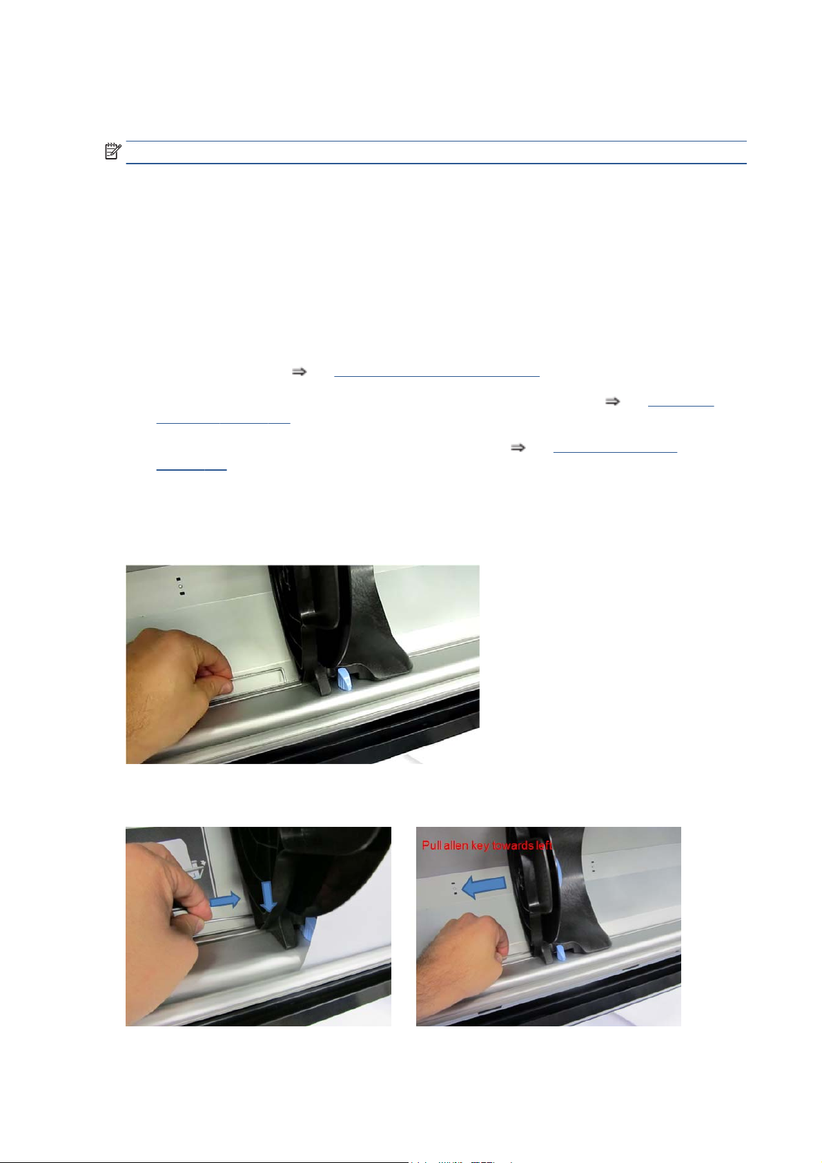
How to remove the Left Hub when the actuator is broken
You need a standard 90º Torx/Allen key(Torx T10 or Allen 2.5).
1. Insert the key about 20 mm between the sheet-metal and plastic parts.
2. Pull the key to the left to release the brake.
10 Chapter 2 Troubleshooting ENWW
Page 21

Troubleshooting paper jams and printhead crashes
NOTE: If you were using HP Coated Paper when the problem occurred, see also Printhead crashes/smears
on high-density prints using coated paper on page 13.
Paper jams and printhead crashes are grouped together because in many cases a paper jam causes the paper
to lift up into the Carriage path and cause a printhead crash, which means that many paper jams are reported
as printhead crashes.
Question Answer
Did the paper jam occur when loading paper? If paper jams have occurred previously, some pieces of paper may
Did the paper jam occur when loading 30 inch wide media? Media may jam due to excessive friction in the opposite edge of
Is the customer using non-HP paper? The use of non-HP paper can easily be the cause of paper jams
TIP: When clearing a paper jam, sometimes paper is stuck in the paper path. To clear this, you must open
the Rear Door and insert thicker paper into the paper path to push out the paper that is still stuck there.
Troubleshooting shutdowns
still be stuck in the paper path. Clear the paper path.
NOTE: Customers often store used rolls without protecting
them from office environmental conditions; when exposed to
high humidity, the paper edges tend to curl. This curling can
cause paper jams when paper is loaded by feeding paper in.
the media loading reference edge. Check that there is no damage
due to the paper feed brake providing more tension than needed
to the media. In this case, replace the paper feed brake. If the
problem persists; escalate to HP Support.
and printhead crashes—especially printhead crashes, because HP
paper is specially formulated to avoid cockle, one of the primary
causes of head crashes. If the paper is not HP-approved, advise
the customer to use HP paper and check to see if the problem is
now solved.
If a shutdown occurs, you will get the message “Switch Power Off” followed by one of these messages:
●
Check Maintenance Cartridge Path
●
Check Paper Path
●
Check Printhead Path
NOTE: A shutdown in each path will require different steps to resolve the problem as explained below. In
each case, make sure that you power off the printer before trying to resolve the problem.
Also check that the Rewinder Motor moves easily (without friction) with the printer turned off.
Maintenance cartridge path
Open the right door of the printer and check for any visible obstacles restricting the movement of the Service
Station. Manually move the Service Station, checking for smooth and free movement.
Paper path
To resolve paper path problems, do the following.
ENWW Troubleshooting paper jams and printhead crashes 11
Page 22

1. Open the Window and check for any visible obstacles restricting the movement of the Drive Roller. Make
sure that the mylar is not damaged. If there is a wrinkled mass of paper inside the paper path, lift the
Pinchwheels (opening the Rear Door) and clear the obstruction.
2. If this shutdown happens at the end of a Roll of Paper, it could be because the paper is stuck firmly to
the Roll. Lift the Pinchwheels (opening the Rear Door) and pull the paper clear.
3. Replace the spindle if broken.
4. Perform the Paper Drive Test to obtain further information on the problem
on page 84.
Printhead path
When a shutdown occurs in the Printhead path, you will get the message “Switch Power Off / Check Printhead
Path (*). The (*) will be a number, which will give an indication on where the failure occurred.
PWM shutdown
To resolve a PWM shutdown, do the following.
1. Clean Slider Rods and Apply Oil along the complete axis of the Slider Rods. After applying the Oil,
perform the Scan-Axis Test
given limits.
2. Clean the Encoder Strip
3. Perform the Scan-Axis Test to obtain further information on the problem
on page 83.
Velocity shutdown
To resolve a velocity shutdown, do the following.
Paper Drive test
See Scan Axis test on page 83 and check that the values are within the
See Clean the Encoder Strip on page 452.
Scan Axis test
1. Open the Window and check for any visible obstacles restricting the movement of the Carriage
Assembly. Try and move the Carriage Assembly manually, checking for smooth and free movement.
2. Check that the Encoder Strip is clean. If necessary, clean Encoder Strip using a damp cloth.
Energy shutdown
To resolve an energy shutdown, do the following.
1. Clean Slider Rods and Apply Oil along the complete axis of the Slide Rods. After applying the Oil,
perform the Scan-Axis Test
given limits.
2. Clean the Encoder Strip
3. Perform the Scan-Axis Test to obtain further information on the problem
on page 83.
See Scan Axis test on page 83 and check that the values are within the
See Clean the Encoder Strip on page 452.
Vacuum suction much lower at high altitudes
At altitudes above 3,000 meters, the vacuum force holding down the paper will be lower, therefore the paper
will not be held in place properly causing:
Scan Axis test
12 Chapter 2 Troubleshooting ENWW
Page 23

●
Ink Smearing on the Paper.
●
Printhead crashes against the Paper.
●
Roll Paper loading problems (low probability).
Banding at variable extreme environmental conditions
NOTE: This problem is only applicable if the OMAS is disabled.
Since the Accuracy Calibration has been done at normal environmental conditions, printing in extreme
environmental conditions will cause banding because the advance of the Drive Roller does not correspond to
the same conditions that the calibration was done in. To solve the problem, perform the Accuracy Calibration
in the new environmental conditions (see Using your printer).
Printhead crashes/smears on high-density prints using coated paper
High density prints can cause cockle mainly on HP Coated Paper. This causes two main problems:
1. Cockling in the borders - Because the printer places too much ink on the Coated Paper, the borders of
the print become raised, causing the Printhead to crash against the paper. To solve the problem, try the
following.
●
Change the paper margins to 15mm, either in the Front Panel or in the Driver. If the customer is
printing PostScript images, send them a PPD file containing the extended margins of 15mm.
2. Cockling within the print - If the printer places too much ink within the print, the paper starts to ripple,
causing the Printhead to smear against the paper. To solve the problem, try the following.
●
Check in the Front Panel if Ink Limiting is ON or OFF. If Ink Limiting is OFF, turn it ON.
●
Never use HP Coated Paper for High Density prints. As a substitute use HP Heavy Coated Paper.
Banding due to ink cartridge replacement while printing
A user has removed the Ink Cartridge while the printer was printing, which has caused the printer to stop. If
the user does not replace the Ink Cartridge immediately, when the printer starts to print again, a band will
appear in the position where the printing restarted. This is because the wet ink interacts with the dried ink on
the paper causing the band to appear. To solve the problem, try the following.
●
Do NOT remove the Ink Cartridge while the printer is Printing. Only replace/remove Ink Cartridges in
between Prints.
●
If the Ink Cartridge was replaced due to the “Empty” status on the Front Panel, then advise the
customer to replace the Ink Cartridge when the “Very Low” status is showing on the Front Panel.
●
Reprint the file (without remove the Ink Cartridge).
34" Rice Paper not supported
Roll width is 34" (non-standard), and the pinch wheels can't control the edge of the paper, causing ink smears
and printhead crashes.
ENWW Banding at variable extreme environmental conditions 13
Page 24
Worm marks on HP Coated Paper with light area fills
Light bands (S-shaped) in the direction of the media axis when light area fills are printed, causing an
unacceptable print-quality defect.
●
Print the Service Configuration Print and check whether the ambient humidity is very low (below 30%).
Increasing humidity may help to reduce the severity of the problem.
NOTE: The paper is causing the problem and not the printer. Do not attempt to replace printer parts to
solve this problem.
Solving paper-handling problems
The front panel keeps indicating that paper Is misaligned or incorrectly positioned.
●
The roll may be loaded the wrong way. The paper should load over the roll toward you.
●
Check that the paper is correctly loaded onto the spindle.
●
The paper may be loaded at an angle. The right-hand edge must be aligned with the blue line on the
Print Platen.
NOTE: Ensure that the paper is wrapped tightly on the roll. This is a very important step to remember
because if this is not done, the paper may be loaded at an angle, causing the paper to be rejected.
●
The Line Sensor may be malfunctioning. See
The Line Sensor has problems detecting paper on page 10.
Difficult to load paper: “Too much skew”
If you encounter a high failure rate when loading paper and the front panel reports “Too much skew” it is
likely that:
●
The encoder strip must be cleaned (this can be carried out by the customer using the User Maintenance
Kit).
●
The Line Sensor must be cleaned.
●
The Blue Line calibration must be performed. See
Platen blue line calibration on page 129.
How to read the power switch LEDs
In certain circumstances, the LEDs located on top of the power switch (located at the rear of the printer)
indicate the status of power supply to the printer.
1. When only the Amber LED is On:
14 Chapter 2 Troubleshooting ENWW
Page 25
●
The printer has been switched Off from the Front Panel (after having pressed the On/Off button).
●
The Power Supply Unit only delivers a 5 V “Standby”; power that is needed to restart the printer
after the Front Panel On/Off button is pressed (the Formatter will start the printer).
2. When the Blue LED is On: Deliver standard “ATX” power for the Electronics Module PCAs (+12V, +5V,
-5V, -12V and so on). All the functions of the Electronics Module are fully operational (Embedded Web
Server and so on).
3. When the Green LED is On: Deliver “analog” 24V and 36V to enable printing.
If you turn on the printer at the front panel, and the Blue LED does not come on, there is a problem. Turn off
the printer using the switch at the rear, then turn it on again using the same switch. If the Blue LED still does
not come on, replace the Power Supply Unit.
If the Blue LED comes on this time, you will probably see an error reported on the front panel as the printer
starts up. If no error is reported, but you continue to have problems when turning on the printer from the
front panel, see
How to read the Formatter LEDs on page 15.
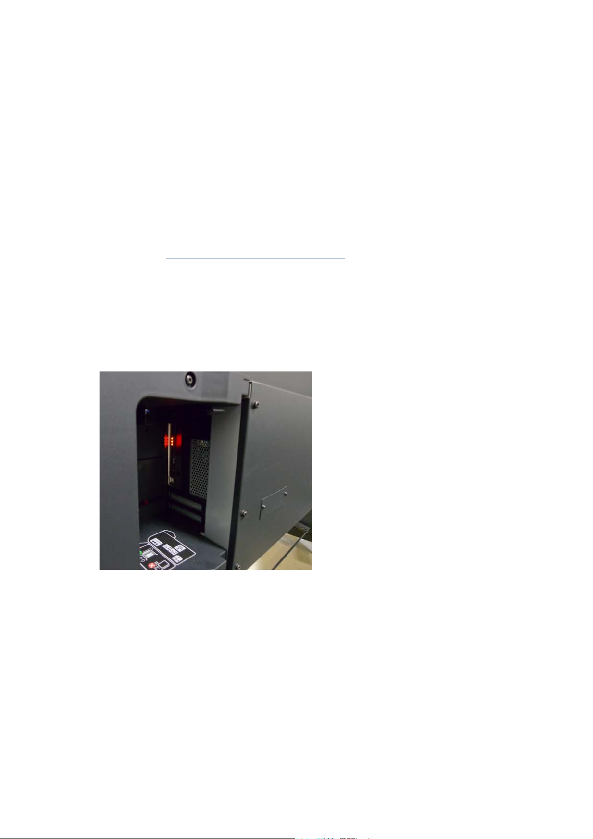
How to read the Formatter LEDs
The LEDs located on the Formatter can help to troubleshoot the printer. The LEDs can either be on or off;
different combinations can indicate different problems.
The following image shows the three Formatter LEDs, which are numbered from the top down: number I at
the top, number II in the middle, number III at the bottom.
Use the following table to interpret the LEDs and find the source of the problem. Remember that you should
read these LEDs when you push the Power button.
Some combinations may require you to replace two or more components. In this case, always replace one
component at a time. Test the printer to see if the problem has disappeared (check the LEDs again). If the
same LED sequence continues, replace the next component indicated in the table.
ENWW How to read the Formatter LEDs 15
Page 26
Power
amber
LED
Power
blue
LED
Power
green
LED
Formatter I
LED
Formatter II
LED
Formatter
III LED
Front
panel
status
Problem and recommendations
Off Off Off Off Off Off Off The printer is not receiving electrical
On Off Off Off Off Off Off The Power key fails to turn on the printer.
Off On Off Off Off Off Off There is a power failure in the Formatter.
power.
1. Ensure that the printer is connected
to the power outlet.
2. Ensure that the outlet delivers the
expected power.
3. Replace the Power Supply Unit.
1. Turn the printer off using the switch
at the rear, and disconnect the
power cord. Reconnect the power
cord and turn on the printer using
the switch at the rear.
2. If the problem persists, replace the
Front Panel.
1. Reseat the power connector in the
Formatter.
2. Replace the Main PCA.
3. If the problem persists, replace the
Formatter.
4. If the problem persists, replace the
Power Supply Unit.
Off On Off On Off Off Off The Formatter BIOS is unable to start.
If an external Memory Module is installed:
1. Reseat the Memory Module.
2. Remove the Memory Module and
restart the printer.
3. If the printer is able to start
normally, replace the Memory
Module. If not, replace the
Formatter.
If an external Memory Module is not
installed, replace the Formatter.
Off On Off Flashing Off Off Off The Formatter BIOS cannot detect the
Off On Off On Flashing Off Off The operating system has experienced a
Hard Disk Drive.
1. Reseat the Hard Disk Drive
connectors.
2. Replace the Hard Disk Drive.
fatal error. Replace the Hard Disk Drive.
16 Chapter 2 Troubleshooting ENWW
Page 27

Power
amber
LED
Power
blue
LED
Power
green
LED
Formatter I
LED
Formatter II
LED
Formatter
III LED
Front
panel
status
Problem and recommendations
Off On Off On On Off Off There is a communication failure with the
Off On Off On On Flashing Off There is an initialization failure in the
Off On Off On On On Off There is an initialization failure in the
If the front panel turns on and then stops
If the power-up process stops while the front panel is displaying a number, respond as follows.
1. If the printer's Power-Up process stops when the front panel is displaying the number 17, this indicates
that there is a problem with the file system on the printer's Hard Disk Drive, so the printer is checking
the whole file system and making any necessary corrections. This problem can arise when there has
been a power cut while the printer was switched On, or if there is a physical problem with the Hard Disk
Drive.
Main PCA.
1. Reseat the Main PCA.
2. Replace the Main PCA.
Formatter. Replace the Formatter.
Front Panel.
1. Reseat the Front Panel cable.
2. Replace the Front Panel.
Checking the whole file system normally takes about half an hour (but could take much longer). There is
nothing that can be done to speed up the file checking process. If you turn Off the printer during the
checking process, the file system check will restart whenever you turn it On again
If you experience this problem repeatedly when there has been no power cut, then this could mean that
the Hard Disk Drive is faulty. In this case, replace the Hard Disk Drive
on page 363.
2. If the printer's start-up process stops when the front panel is displaying any other number between 1
and 30, then try the following.
●
Turn the power off at the rear of the printer and disconnect the power cord. Reconnect the power
cord and turn on the printer.
●
If the printer continues to stop during the power-up process, replace the Hard Disk Drive
Hard Disk Drive (HDD) on page 363.
How to interpret the Service Information Pages
The Service Information Pages contain the following information:
●
Current Configuration
●
Current Information
●
Usage Information
See Hard Disk Drive (HDD)
See
●
Event Logs
●
Calibration Status
ENWW If the front panel turns on and then stops 17
Page 28
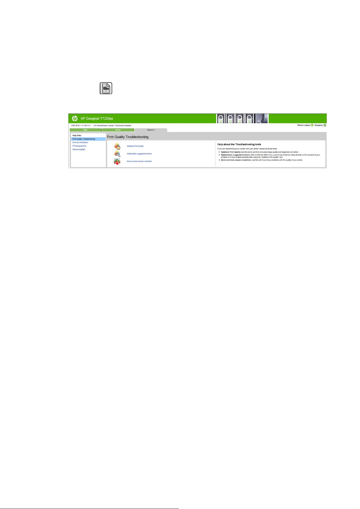
●
Connectivity Configuration
●
All Pages
It is possible to print the Service Information Pages either through the Front Panel or through the Embedded
Web Server:
●
Front Panel:
●
Embedded Web Server: Support tab > Service support > Printer information.
Even if the printer cannot print, the Information Pages are still accessible through the Embedded Web Server.
Main characteristics
●
Only available in English (except the current information page).
icon > Service information prints.
●
From the Front Panel, you can choose to print all pages or just select the specific pages that are needed.
If all pages are printed:
◦
Nesting is turned on automatically (and turned off once all the pages have been printed).
◦
Nesting cannot be mixed with other jobs in the queue.
●
Each page can be printed from the Web browser when using the Embedded Web Server.
●
Each page can be sent by e-mail from the Web Browser when using the Embedded Web Server (File ⇒
Send ⇒ Page by E-mail).
●
You can see the same information through the Front Panel or the Embedded Web Server.
Current configuration
This page contains full details of the current configuration of the printer.
18 Chapter 2 Troubleshooting ENWW
Page 29
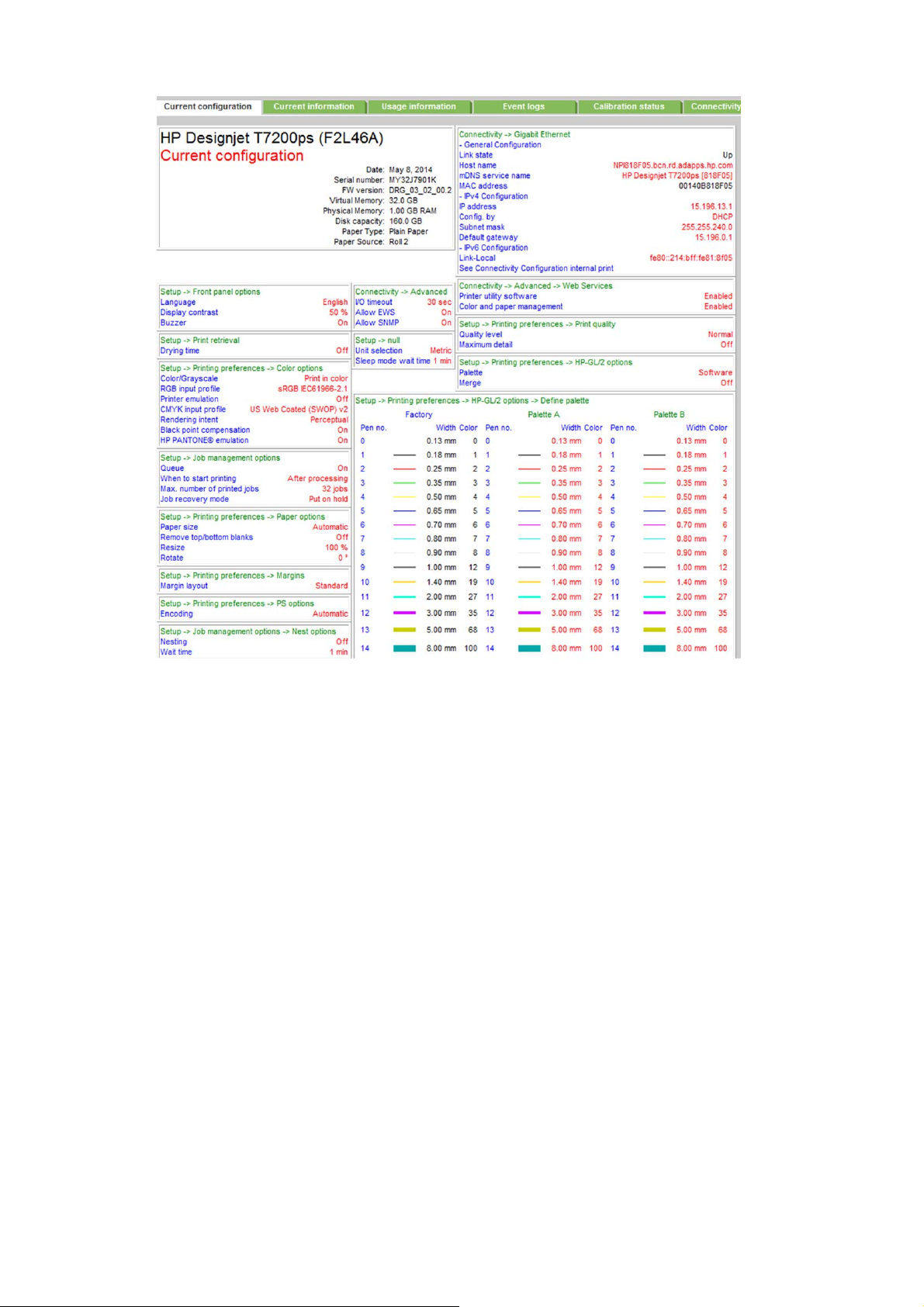
Current media, printhead and ink information
This page contains the following information:
●
Current Printer Configuration.
●
Paper Loaded Information.
●
Current Printhead Kit Information.
ENWW How to interpret the Service Information Pages 19
Page 30
●
Current Ink cartridge Information I and II.
The first two lines are available at the beginning of each Service Information Page and contains standard
information (like Service ID, firmware version).
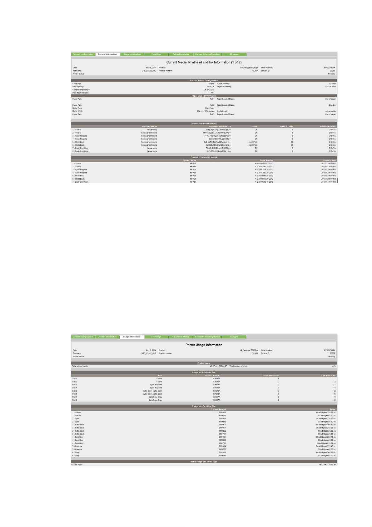
Printer usage information
This page contains the following information:
●
Printer Usage
●
Usage per Printhead Slot
●
Usage per Cartridge Slot
●
Media Usage per Paper Type
●
Component Usage
●
Spittoon Usage
●
Preventive Maintenance Usage
20 Chapter 2 Troubleshooting ENWW
Page 31

Media used sections
●
Total media used in the printer.
●
Media used for each media type.
It is possible that the sum of the media used for each media type is lower that the total amount of
media used in the printer. This is because only the total media used in the printer is saved in the backup
EEROM which is located in the ISS PCA. When the Hard Disk Drive is replaced, the total media used per
media type is reset to zero (0), but the total media used is recovered from the backup EEROM.
Printhead section
The Printheads section displays the Printhead usage per slot.
●
Total Insertions: This is linked with the crane of the Ink Supply Tubes. When the Ink Supply Tubes are
replaced, the total insertions amount will be reset to zero (0).
Cartridge section
The Ink Cartridges section displays the ink usage per cartridge.
Preventive maintenance section
Once the value reaches 100%, the corresponding Preventive Maintenance Kit should be used. For further
details, see
Preventive maintenance on page 449.
Component usage
One cycle is counted when the Carriage makes one movement to the left of the printer and then returns to
the right.
To find the total of Monochrome ink consumed in cc use the the formula ^0.61. Example: For a value marked
as 11504, use the formula ^0.61 to convert it to cc=300cc (11504
Spittoon section
This section contains information on the different Spittoons located in the printer.
Event logs
This page contains the following information:
●
Last 20 System Error Codes (which prevented the printer from booting).
●
Last 20 System Warnings (which did not prevent the printer from booting, but which required the user
to acknowledge the problem).
0.61
=300).
ENWW How to interpret the Service Information Pages 21
Page 32

●
Printhead Error log.
System/Warning error
●
The Line and Internal Code do not provide much information, but are useful in the case of escalating a
problem to the division (different internal error codes can point to the same error code (e.g. 01.10:10)).
●
Media Usage (in square meters) and Date (from the printer’s Internal Clock (RTC)) help you to
understand if the printer has been used (media usage) and how much time has passed since the last
error.
Printhead error log
●
Printheads ago: History of the last three Printheads used (’0’ represents the current Printhead used).
●
Status:’0’ = Working,’1’ = No Printhead Detected,’2’ = Replace,’4’ = Reseat,’8’ = Remove.
●
% Ink Used: Percentage of the warranty life (1200 ml).
●
Error Code: Specific error code generated by the printer when the Printhead has been replaced.
●
Max Recovery:
◦
0: No manual Printhead recovery has been performed on the Printhead.
◦
1 or higher: At least one Printhead recovery has been performed.
Calibration status
This page contains the following information:
●
General Calibrations (performed by Service Engineers).
22 Chapter 2 Troubleshooting ENWW
Page 33

●
Media Specific Calibrations (performed by the User).
General calibrations
●
Printhead Alignment relates to the Printhead Alignment which changes to ‘pending’ when a Printhead
is replaced and the Printhead Alignment has not been performed.
NOTE: When a component is replaced, the corresponding calibration is NOT automatically set to ‘NOT
DONE‘. This is because the printer does not know that there is a new part installed.
●
Drop Detector relates to the Drop Detector or Service Station calibration.
●
Line Sensor relates to the Line Sensor Calibration.
Media-specific calibrations
This section shows the following for each type of media:
●
Media Name
●
Color
●
Paper Advance
Connectivity configuration
This page contains full details of the current configuration of the printer.
ENWW How to interpret the Service Information Pages 23
Page 34

When the main window is open and the printer is printing (safety compliance)
We describe the details of the behavior of the printer when the window is opened while the carriage is
moving.
If the main window is opened while the printer is doing something, be it a swath of a print job or a system
task, the printer will:
1. Before the carriage stops, it will finish whatever it was doing when the window was opened. It will not
finish an image it was printing, but it will finish the current swath, so as to avoid any impact on image
quality. If it was performing a system task it will finish it before stopping.
2. If the carriage finishes on the left side of the printer, the carriage will always slowly move to the right
side of the printer.
3. The printheads will be placed in their 'capping' positions.
Here are some different scenarios of what happens when the window is opened:
●
If the printer is printing an image when the window is opened: The carriage will not stop immediately,
the printer will finish the swath and then stop. If the cover is then closed, the printer will start to print
from the position it was stopped.
●
If the printer is cutting the media: The carriage finishes the cutting procedure.
●
If the printer is checking the SKEW while loading the media: During the skew check, the printer does
small movements of the carriage on the right side of the printer, and also moves the media when
needed. This procedure checks that the edge of the media is moving laterally or not. If the window is
opened while the printer is checking the media SKEW, the printer will complete the skew procedure (and
it will continue well after the window has been opened). This is the only case when the printer will not
stop the carriage at the end of a lateral movement (as a swath).
The safety system in place is designed to detect an object in the path of the carriage as it moves across the
printer, any object encountered will cause the system to shut down the driver motor in the carriage. This
method of ensuring safety is considered sufficient by the regulatory agencies that inspect and assess the
product prior to its placement in the market. The window and its switch are considered a ‘supplementary’
safety feature, and as such the behavior of the switch has been adjusted as a trade off between the level of
safety provided and the printer’s functionality.
24 Chapter 2 Troubleshooting ENWW
Page 35

How to troubleshoot the 79:04 system error
●
Introduction
●
Possible causes
●
Troubleshooting based on symptoms
Introduction
The System error 79:04 is a generic firmware error (equivalent to a blue screen in Windows). It’s the System
Error that the printer will display when an unknown exception occurs that cannot be pointed to by any
specific subsystem of the printer.
Since this is a generic error, there can be multiple causes behind it. This document will cover the most
probable causes behind a system error 79:04 and will recommend the most efficient troubleshooting steps
to resolve customer issues.
One important point to mention is that, although 79:04 system errors can be caused by a hardware
malfunction, the vast majority of 79:04 system errors are pure software or firmware issues. In these cases
the issue can only be solved by determining the root cause and implementing a solution. The solution can
usually be applied by either correctly configuring a selection, updating the printer’s firmware/software that is
being used or by fixing an error in the code).
Possible causes
Since the 79:04 system error is a generic error, the number of possible causes behind it is large. The majority
can be grouped, however, into the following groups.
Job-related SE 79:04
A specific print job that is not correctly formatted for the printer or that is not correctly processed by it can
trigger a 79:04 system error.
The incorrect format or processing can come from two sources:
●
Incorrect commands in the job itself: for example, a PS job with some commands that do not have the
correct PS format
●
Issues applying to the settings in the job
Cause
A system error 79:04 caused by a print job always has the same symptoms:
1. The job is received by the printer and starts to process.
2. In the middle of the processing, the printer stops and displays 79:04.
3. The printer displays the 79:04 system error again immediately after restart. This is because the printer
tries to reprint the job, which is pending in the queue, after restart.
4. After the second restart, the printer will start normally.
5. If the same job is sent again, it always produces a 79:04 system error.
These types of 79:04 system errors are normally caused by jobs that have been generated by third-party
applications (RIPs, third-party drivers, files exported by an application to PS, PDF, HP-GL/2, RTL, or any other
format supported by the printer). Jobs generated by HP drivers will not normally generate 79:04 system
errors, since the output that our drivers generate is under control and has been designed taking into
consideration the characteristics of our printer’s language interpreters.
ENWW How to troubleshoot the 79:04 system error 25
Page 36

Solution
As an exception to this general rule, there are certain applications that can generate their own PS code, such
as Adobe PhotoShop, Adobe Illustrator, Adobe Acrobat, Corel Draw, Freehand and QuarkXpress. When used
with a PS driver, these applications generate the output PS themselves, instead of using the driver’s
rendering capabilities. This is known as PostScript pass-through. So, when using an HP PostScript driver
together with an application that has PS passthrough capabilities, the PS code that comes into the printer has
not been rendered by the HP driver, and, should the source file contain any PS commands that are not
correctly processed by the printer, a 79:04 system error could occur even though an HP driver is being used.
When a job consistently generates a 79:04 system error, it is either because of a issue in the printer’s
firmware or because of a defect in the job itself (when it has been generated by third-party software). In
order to identify the cause and find out a solution, these issues should always be immediately escalated to
the GBU through the GCC.
However, there are some workarounds and short-term solutions that can be tried in order to get the
customer up and running in the shortest possible time.
1. Send the job using a variety of different settings. The issue is often caused by a combination of the job
contents combined with some specific setting(s).
2. If the customer is sending the file directly to the printer, try using the HP driver instead.
3. If the issue occurs when printing through the HP PostScript driver from an application with PS
passthrough, try changing the options in the application so that it prints PS as raster (the option is
typically located in the Advanced options of the application’s printing dialog).
Data-related SE 79:04
The printer has a hard disk and non-volatile memory that contain databases and files that can be modified by
the customer. Some examples include:
●
The printer’s queue
●
The hard-disk partitions that contain the customer's jobs
●
The database that stores printer settings
●
The database that stores accounting information
Some of these data are accessed by the printer at start-up time, and some others are accessed as needed.
If any of these fields contain corrupt data or data with characters or values that cannot be correctly
processed by the printer, a 79:04 system error may occur.
Cause
There are two different types of symptoms for data-related 79:04 system errors.
1. When the corrupt data are accessed during start up:
a. The printer will display a 79:04 during the start-up process
b. Switching the printer off and on again will not solve the issue. The printer will continue displaying
the 79:04 system error until the corrupt data have been cleared through a service procedure.
2. When the corrupt data are accessed during normal printer operation:
a. The printer will start up normally.
b. When the data are accessed (for example while printing, while navigating the queue or when
changing some settings), the printer displays a 79:04 system error.
26 Chapter 2 Troubleshooting ENWW
Page 37

Solution
c. The printer can restart normally.
d. When the data are accessed again (typically, under the same conditions as in step b), the 79:04
system error is displayed again.
Data-related 79:04 errors are often resolved by means of hardware intervention. Since data are stored in
physical components (RAM, EEROM and hard disk), replacing these components with new ones that are
empty usually solves the problem. However, there are quicker and more effective solutions to these types of
errors.
1. Clear all information that has been introduced by the customer using the standard tools available in the
printer.
a. Delete all jobs from the queue (from the front panel or the Embedded Web Server).
b. Reset to factory defaults to clear the customer’s configurations and calibrations.
c. Delete any non-standard paper presets in the printer (both the ones that have been created by the
user and the ones that have been installed as OMES profiles through the Embedded Web Server or
the HP Utility).
2. If step 1 did not resolve the issue, you can use Service Tools to clear additional information that could
be causing the issue.
a. Start the printer in Diagnostics Boot Mode.
b. Perform an EEROM reset.
3. If step 2 did not resolve the issue, it is possible to clear all the information on the hard disk and the
different EEROMs, leaving them as they were when the printer was new.
a. Access the Service Utilities Menu.
b. In the Secure Disk Wipe menu, set the Sanitize level to Insecure mode.
c. Execute the disk wipe. This will clear all partitions on the hard disk that contain customer data,
including the partition in which the operating system is installed. After the disk wipe has
completed, a backup firmware version will automatically be installed from a backup partition to
allow the printer to start up. This backup firmware is a very old version.
d. The firmware in the printer should be updated to the latest official version as soon as the printer
has restarted.
After step “c”, any 79:04 which is caused by corrupt data in the printer will be solved.
NOTE: It is possible that the corrupt data came to be in the printer as a consequence of some activity
in the customer’s workflow. In this case, it is possible that the issue will happen again. In these cases, it
is very important to understand the sequence of events in the customer’s workflow that led to the error
occurring. Once the error can be traced in the customer’s workflow, escalate the issue to the GBU
(through the GCC). This is done to implement any changes in the printer’s firmware that can prevent
these issues occurring again.
Network-related SE 79:04
The printer has built-in networking capabilities. Network settings can be set manually, but in most cases they
are obtained automatically from the printer. These settings include many different fields, such as IP address
and subnet mask, available gateways, host and domain names and so on.
In some cases, there can be issues in the firmware that can cause a certain value in one of these fields to be
interpreted incorrectly, and this can lead to a 79:04 system error.
ENWW How to troubleshoot the 79:04 system error 27
Page 38

Cause
Solution
There is no single set of symptoms that can absolutely pinpoint a network-related 79:04 system error.
However, the following guidelines can be applied.
●
It can happen at start-up time or when accessing the Network Configuration section of the front panel.
●
In both cases, repeating the action with the LAN cable disconnected does not cause the 79:04 to occur.
In the majority of cases, these issues will be due to an issue in the printer’s firmware. As soon as the
conditions in which the issue happens can be understood, it should be escalated to the GBU through the GCC.
At the same time, the following short-term solutions and workarounds can help the customer to get up and
running in the shortest possible time.
1. Disconnect the network cable to be able to start the printer and change network settings.
2. In the Network configuration menu in the Front Panel, disable any protocols that you are not using,
including IPv6, SNMP and WebServices.
3. If step 2 does not work, try configuring the printer manually.
a. Enter the correct subnet mask and an IP address in the valid range.
b. In the Gateway field, set the same value as in the IP address field.
c. Do not set a host name or a domain name.
4. If step 3 does not work and the customer is using the network card built into the printer, try using an
accessory Jetdirect card instead.
User-interaction-related SE 79:04
In some cases the printer may not react as expected when a certain set of conditions coincide. In these cases,
if the printer doesn’t know how to react, it may simply display a 79:04 system error and force a restart. Here
are some examples (not real) that may help to illustrate this.
●
An error occurs when a job is cancelled when it is at the “Finishing print” state and when the queue is
disabled.
●
An error occurs if the Window is opened while the printer is checking the printheads.
These errors will probably happen only in very specific corner cases that have not been identified during the
development or the qualification of the printer. Therefore they do not normally impact the customer
severely, as they do not affect their usual workflows.
Cause
The symptoms here are as numerous as the number of possible interactions between the user and the
printer. In any case, it’s possible to identify the steps that caused the error to occur and avoid them as the
steps will always be the same with no variance.
Solution
First identify the state the printer was in at the time the error was displayed. For example, an action taken
when the printer is drying can produce an error, whereas the same action when the printer is doing
something else (or is idle) may not produce any error.
When you have identified the steps that caused the error, proceed as follows.
28 Chapter 2 Troubleshooting ENWW
Page 39

1. Escalate the issue to the GBU through the GCC in order to have it corrected in the firmware.
2. Recommend to customers that they try to avoid the same steps to avoid the error.
3. If the conditions that cause the error are in the customer’s regular workflow, try to identify a different
way of achieving the same result.
Random SE 79:04 (memory leaks and concurrence issues)
Some 79:04 errors can happen randomly when the printer is heavily used. However, it’s impossible to find a
single set of conditions that reproduce the problem. It just happens from time to time, without a defined
pattern.
These random 79:04 errors can have two different types of root causes.
●
Memory leaks: Before a program is executed, it allocates the memory it will need. After the execution is
complete, the allocated memory is freed to be used by other programs. If the allocation or the release
of the memory are not properly programmed, every time the program is executed some memory will be
incorrectly labelled (either as used or as free). This is known as a memory leak. When a program with a
memory leak is executed a lot, the memory becomes progressively full (since it is not properly freed).
When the leak becomes too big, the printer is left ‘out of memory’ to execute new processes and a
79:04 is triggered.
●
Concurrence issues: There are certain resources that can be accessed by multiple programs or by
multiple executions of the same program (what is known as multiple threads). Access to these
resources must be correctly controlled to prevent unexpected behavior. Issues caused by incorrect
control of these resources are concurrence issues.
Cause
For example, imagine that there is a counter that controls the communication between the Jetdirect card and
the printer’s firmware. Whenever a new packet of information is sent by the Jetdirect card to the printer, the
counter increases. When the printer receives the packet and processes it correctly, the counter decreases.
Another process checks the counter from time to time to see its value and draw conclusions from it. If the
counter is near 0, it means that the printer is processing correctly, and if it grows too large, it may mean that
there is a bottleneck somewhere and maybe the Jetdirect card throughput is decreased to control its speed
to the printer. However, if the access to this counter is not properly controlled, undesirable effects may
happen: in a real environment, a Jetdirect card processes thousands of information packets per second, so
this counter is updated frequently, both by the Jetdirect and the printer. If at a certain point the Jetdirect card
and the printer try to access the counter at the same time and the code is not prepared to handle this, it may
happen that the Jetdirect cannot increase the counter because the printer is writing to it, and what’s worse, it
does not realize this fact. If this happens a few times each second, it may happen that the counter is
decreasing faster than it’s increasing and that at a certain point it has a negative value. And then, what will
the process that is checking this counter do? Most likely, the process will not be prepared to react to a
negative value and will launch an exception that will trigger a 79:04 system error.
This type of 79:04 error always occurs in heavy load conditions, so the symptoms will normally follow this
pattern.
●
A printer that is heavily used (printing a project or in a reprographics environment) produces 79:04
errors randomly, forcing the user to restart.
●
After restarting, the printer can be used without any issues for an extended period of time, but if the
workload is consistently high a random error will occur again.
●
The error can never be associated with a specific file. The file that was being printed when the error last
occurred can be printed without issues after restart. And a file that has been printed without issues
several times can trigger the error in the future.
●
This error is very dependent on the customer's workflow. The most common user workflows have been
extensively tested both by HP and by our beta sites, so random 79:04 issues are most unlikely to occur
ENWW How to troubleshoot the 79:04 system error 29
Page 40

Solution
in these cases. These random issues tend to occur in very specific corner cases, and cannot be
reproduced unless the exact conditions of the workflow are replicated. They normally happen when
sending files generated by external applications (RIPs, third-party drivers, and so on).
Random 79:04 errors are, by far, the most complex ones to diagnose and to fix. The only solutions available
in these cases are as follows.
1. Identify the root cause (either in the files or in the firmware) and fix it in the code, which requires the
intervention of the GBU.
2. Test any options available to modify the customer’s workflow and see if any combination of them
solves the issue.
In both cases, a profound understanding of the customer’s workflow is necessary. The following information
should be obtained.
●
The front-panel settings
●
The application, and the RIP or driver that are being used
●
The application/RIP/driver settings
●
The type of output files that this application, RIP or driver is generating
●
Some sample files that are representative of what the customer is using
●
The operating system
●
The method of connection to the printer
●
A description of the normal flow when the issue occurs and the typical frequency of occurrence (for
instance, once every hour when sending several files non-stop, each of them with multiple copies)
With this information, the environment can be replicated in order to try to find workarounds. This is also the
information that will be needed at the GBU to investigate and fix the root cause of this issue once it is
escalated.
Hardware-related SE 79:04
Hardware is, by far, the least likely cause of a 79:04 system error. Replacing hardware components does not
normally fix the issue and increases the total turnaround time in finding a workable solution.
In some cases, a failure in a component in the printer’s electronics may cause a 79:04 system error, since the
printer’s electronics are involved in the execution of the firmware and the processing of jobs. However,
hardware failures in the electronics tend to produce specific system errors that point directly to the
component that is failing.
Some hardware causes that could be behind a 79:04 error are as follows.
●
Defective clusters on the hard disk. If these clusters are used to execute the firmware or to process a
job, they may produce a 79:04 error. However, most 79:04 errors that are solved by a hard disk
replacement are in fact, data-related 79:04 errors that could have been solved more efficiently and
quickly by following the recommendations for such an error.
●
Defective memory segments. If the RAM memory has some defective segments, a 79:04 error may
occur when these segments are used.
●
Intermittent defects in the electronic components that are involved in the processing of a job: Carriage
PCA, Trailing Cable, Formatter and PrintMech PCA. This is a highly unlikely cause, since defects in these
components will produce subsystem-specific errors.
30 Chapter 2 Troubleshooting ENWW
Page 41

Cause
Solution
There’s no single set of symptoms behind hardware-related 79:04 system errors. However, there are two
relatively common causes.
●
79:04 during start-up. Restarting the printer may or may not solve the problem.
●
79:04 while processing or printing a job. Restarting the printer and printing the same job does not
always produce the error.
In the following procedure, perform each step as it appears in the list and move on to the next step only when
you are sure the 79:04 error has not been cleared.
1. Restart the printer in Diagnostics Boot mode and execute the service tests to check the functionality of
all the electronics components.
2. Check for data-related system errors: see
3. Replace the memory.
4. Replace the hard disk drive.
5. Escalate the issue before replacing any additional parts.
Troubleshooting based on symptoms
This section will describe which troubleshooting steps to perform for a 79:04 system error based on the
symptoms of the issue. Perform each step as it appears in the list and only move on to the next step once you
are sure the 79:04 error has not been cleared.
Front panel displays 79:04 at start-up
1. Restart the printer twice. If the system error has been caused by a job in an incorrect format, restarting
twice clears the error (the first time after restart, the printer tries to print the job again, which causes
the error to re-appear). If restarting the printer twice solves the issue, then it is an issue related to the
job: see
2. Update the printer’s firmware. Even if the currently installed firmware version is the latest, reinstall it.
Since the printer cannot start normally, you must update the firmware while starting the printer in
Diagnostics Boot Mode.
3. Disconnect the network cable and restart the printer. If this solves the problem, then it is a network-
related 79:04 error and you should follow the guidelines for this type of 79:04 error, see
related SE 79:04 on page 27.
Job-related SE 79:04 on page 25.
Data-related SE 79:04 on page 26.
Network-
4. Remove all cartridges, printheads and the maintenance cartridge. Unload the paper. Restart the printer.
If the printer can start normally, insert the consumables one by one until you isolate the one that is
causing the error. Do not insert any of the replaced consumables in another printer.
5. Restart the printer in Diagnostics Boot Mode and perform the “Electronics test”. If an electronic
component is identified as faulty, replace it.
6. Restart the printer in Diagnostics Boot Mode and Reset the EEROM. If the issue is solved by this, this is a
data-related 79:04 system error and you should follow the guidelines, see
on page 26.
7. If the unit has been used for some time and suddenly has started to show this behavior, replace the
Hard Disk Drive (it may be included with the Formatter in some models).
ENWW How to troubleshoot the 79:04 system error 31
Data-related SE 79:04
Page 42

8. If the issue is new and the issue happens since the first boot, do not replace the Hard Disk Drive.
9. If none of the previous steps solved the issue, escalate the issue with the following information:
●
Unit information: S/N, P/N, accessories
●
Conditions where the problem occurs and conditions prior to the first occurrence of the problem
●
The results of the previous steps
●
The System Error detailed information (this can be obtained by pressing CANCEL + Down)
●
The printer logs
Front panel displays 79:04 during printer operation – not while sending jobs
1. Restart the printer.
2. Update the printer’s firmware. Even if the currently installed firmware version is the latest one, reinstall
it.
3. Reset the printer to factory defaults.
4. In order to narrow the scope of the issue, try the following.
a. Disable the queue
b. Disable any unused network protocols
c. Disable SNMP and WebServices (if they are available in the printer)
d. Disable “Sleep mode” from the Service Utilities menu
e. Delete any Paper Presets that you may have uploaded or created using the printer
Spectrophotometer.
5. Restart the printer in Diagnostics Boot Mode and perform the “Electronics test”. If an electronic
component is identified as faulty, replace it.
6. Restart the printer in Diagnostics Boot Mode and Reset the EEROM. If the issue is solved by this, this is a
data-related 79:04 system error and you should follow the guidelines for this type of error, see
related SE 79:04 on page 26.
7. Format the Hard Disk. To do so, you will need to start the printer normally, enter the Service Utilities
menu and then the Secure Disk Erase option. Set the Erase method to “Fast Erase” and then perform the
disk erase process. This will take 45-75 minutes and will erase all user information from the disk,
resolving any issue caused by corrupt data. After the erase process, a firmware update will be required.
If this solves the issue, this is a data-related 79:04 system error and you should follow the guidelines
for this type of 79:04, see
8. Try to identify the combination of settings or actions that led to the system error and try to reach the
same result with a different combination. Escalate the issue to fix the original problem.
9. If none of the previous steps could solve the issue, escalate it with the following information:
●
Unit information: S/N, P/N, accessories
Data-related SE 79:04 on page 26.
Data-
●
Conditions where the problem occurs and conditions prior to the first occurrence of the problem
●
The result of the previous steps
●
The printer information pages (either printed and faxed or obtained through the Embedded Web
Server)
32 Chapter 2 Troubleshooting ENWW
Page 43

●
The System Error detailed information (it can be obtained by pressing CANCEL + Down)
●
The printer logs
Front panel displays 79:04 while printing
●
A. While printing a single job
●
B. Random 79:04 during continuous printing
A. While printing a single job
The error happens after a single job is sent. It’s easy to identify which job that has produced the error, since
every time that this same job is sent, the error is replicated.
1. Restart the printer twice (after the first restart, the printer will show the 79:04 system error again, since
the printer will attempt to reprint the last job in the queue, which is the one that caused the issue)
2. If you are using an HP driver, update the driver to the latest version
3. Update the printer’s firmware. Even if the currently installed firmware version is the latest one, reinstall
it. Send the job using different print settings. The following ones can be helpful:
a. Try sending the job without selecting a paper preset in the driver
b. Try changing the Image Quality settings
c. If you are using the HP-GL/2 driver, try the option “Send job as bitmap”
d. If you are using the PS driver, try using the HP-GL/2 driver instead
e. If you are using the PS driver from an Adobe application (or any other application that can handle
PS), try changing the application’s print settings so that the PS is generated as Raster.
4. Try the following Front Panel settings:
a. Change the Print Language option in the Front Panel from “Automatic” (which is the default
setting) to the language that is being printed (PS, HP-GL/2, …)
b. Queue = OFF
c. Start Printing = After processing
d. For PS SKUs, try changing the encoding setting (“Automatic” by default) to Binary or ASCII
5. If you are using a third-party application that does not print through the HP driver, try modifying the
printing workflow by:
a. Using an HP driver
b. Changing the settings in the application’s printing dialog
6. If you are using an accessory Jetdirect card, try using the internal network connector or USB (if
available).
7. Escalate the issue, providing the following information.
●
Unit information: S/N, P/N, accessories
●
Conditions where the problem occurs and conditions prior to the first occurrence of the problem
●
The results of the previous steps
●
The printer information pages (either printed and faxed or obtained through the Embedded Web
Server)
ENWW How to troubleshoot the 79:04 system error 33
Page 44

●
The System Error detailed information (it can be obtained by pressing CANCEL + Down)
●
Information on the workflow:
◦
Operating System
◦
Application
◦
Driver
◦
Settings in the driver and the application
◦
Settings in the printer
◦
Connection method and settings:
●
The original file along with the information on how to reproduce the issue
●
A print to file that can reproduce the issue
●
The printer logs
B. Random 79:04 during continuous printing
The error does not happen with a single job. It happens randomly during continuous printing, normally while
the printer is managing a heavy load (printing a project or in a reprographics environment).
This type of error is caused either by memory leaks or by concurrence issues in the printer’s firmware. They
normally happen in unusual environments where these memory leaks or concurrence issues that have not
been detected during qualification have occurred. These issues cause the printer to crash at a completely
random moment during printing, and are not associated to a specific job.
Because of this, troubleshooting these issues is normally quite complex.
1. Restart the printer twice (after the first restart, the printer will show the 79:04 system error again, since
the printer will attempt to reprint the last job in the queue. If the issue continues occurring randomly,
continue troubleshooting.
2. If you are using an HP driver, update the driver to the latest version.
3. Update the printer’s firmware. Even if the currently installed firmware version is the latest one, reinstall
it.
4. Try the following changes in the workflow:
a. Change the Print Language option in the Front Panel from “Automatic” (which is the default
setting) to the language that is being printed (PS, HP-GL/2, …)
b. Queue = OFF
c. Start Printing = After processing
d. For PS SKUs, try changing the encoding setting (“Automatic” by default) to Binary or ASCII
e. If you are using the HP-GL/2 driver, try sending the job as a bitmap
5. If you are using a third-party application that does not print through the HP driver, try modifying the
printing workflow by:
a. Using an HP driver
b. Changing the settings in the application’s printing dialog
6. Escalate the issue with the following information:
34 Chapter 2 Troubleshooting ENWW
Page 45

●
Unit information: S/N, P/N, accessories
●
The printer information pages (either printed and faxed or obtained through the Embedded Web
Server)
●
The System Error detailed information (it can be obtained by pressing CANCEL + Down)
●
Information on the workflow:
◦
Operating System
◦
Application
◦
Driver
◦
Settings in the driver and the application
◦
Settings in the printer
◦
Connection method and settings
●
Exact information on how to replicate the environment that reproduces the issue, including some
example files that can be sent to the printer to replicate a heavy load environment. These files will
need to be:
◦
Original application files, if the issue happens printing from an application through our driver
◦
Print to files if the issue happens when printing from a third-party application
ENWW How to troubleshoot the 79:04 system error 35
Page 46

36 Chapter 2 Troubleshooting ENWW
Page 47

3 System error codes
●
What to do if the front panel is blank
●
System error codes
●
Explanation of system error codes and warnings
●
Continuable and non-continuable error codes
ENWW 37
Page 48

What to do if the front panel is blank
No system error message can be displayed when the front panel is blank. In these cases the front panel has
not necessarily failed—any other electronic component can be the root cause. The Power Switch and
Formatter LEDs can help you to troubleshoot a problem in this situation; see
LEDs on page 14 and How to read the Formatter LEDs on page 15.
System error codes
System error codes are hexadecimal numbers generally caused by internal system errors. The following
pages contain a list of system error codes and their respective descriptions and recommended corrective
actions. Try one recommended action at a time and check whether the error code has disappeared.
If you have an error code which is not documented in this Service Manual or you have an error which you
cannot resolve, then report the error to the HP Response Center or the nearest HP Support Office. When
reporting the error, have the following information ready:
●
Model and Serial Number of the printer.
●
Which firmware revision the printer is using (see Note below). Check firmware in Setup Menu /
Information Menu / Show Printer Information.
●
The complete error number (see Note below).
●
The complete error number (see Note below).
How to read the power switch
●
The Service Configuration Print.
●
The Current configuration sheet.
●
Which software application the customer is using (name, version and so on).
NOTE: When reporting the System Error Code, make sure that you supply the full Internal Error Code and
the firmware version. Without this information, HP Support Personnel cannot help you. To view the Internal
Error Code, hold the DOWN key and press the CANCEL key at the same when the System Error Code is
displayed on the Front Panel.
Explanation of system error codes and warnings
System Error Codes explain which component/system is failing and what action should be taken to resolve
the problem.
System Error Codes are displayed directly on the front panel (but can also be seen on the Information Page)
and have been defined in the format XX.YZ. or XX.n:YZ.m.
●
XX: Service Part (2 digits).
●
n: Service Part Index (if more than one used in the product) - Optional.
◦
e.g. Identify the Ink Supply (color and number).
38 Chapter 3 System error codes ENWW
Page 49

●
Y: Who should perform the action (1 digit) - (User or Service Engineer).
●
Z: Action to perform (1 digit).
●
m: additional actions/information to consider (1 digit) - Optional.
◦
e.g. Non-authorized ink was detected, PM was triggered or Printhead in/out of Warranty.
The following table explains the XX part of the System Error Code or Warning:
Code Component/System
01.0 Main PCA
01.1 Printmech PCA
01.2 ISS Top PCA
01.3 ISS Bottom PCA
02.1 Carriage PCA
03 Power Supply Unit
05 Formatter
05.1 Formatter Fan
06 Hard Disk Drive
08 Front Panel
11 Trailing Cable
17 Other cables
21 Service Station
23 Air Pressure System (APS)
24 Ink Supply Tubes
26.n Ink Cartridge (color n)
27.n, 28.n Printhead (color n)
29 Maintenance Cartridge
41 Media-Axis Motor
42 Scan-Axis Motor
43 Vacuum Fan
44 Aerosol Fan
45 Rewinder
46 Primer
50 OMAS
51 Window Position Sensor
51.1 Maintenance Cartridge Door Sensor
52 Drop Detector
53 Media Sensor
55 Line Sensor
56 Paper Encoder Sensor
ENWW Explanation of system error codes and warnings 39
Page 50

Code Component/System
59 Incompatible parts
60 Initialization
61 Language Interpreting
64 Input/Output through USB Port
71 Memory Management
74 Firmware Update
75 Ink consumption
76 Hard Disk Full
77 Embedded Web Server
78 Media Settings
79 Assertion (Uncontrollable Firmware Error)
81 Paper Advance
85 Media-Axis Encoder Reading
86 Carriage Movement
87 Scan-axis encoder reading
94 Color Calibration
The following table explains the YZ part of the System Error Code or Warning:
Code Recovery action Response
00 Replace
01 Reseat/Reconnect/Clean/Adjust (manually)
02 Calibrate/Adjust (using Automatic Process)
03 Power OFF and Restart the printer
04 Update System Firmware
05 Upgrade Driver or Computer Software
06 Add Accessory
07 Escalate
08 Send Plot Again
09 Wrong Part Installed
10 Replace
11 Reseat/Reconnect/Clean/Adjust (manually)
Possible for customer to perform action
12 Calibrate/Adjust (using Automatic Process)
13 Power OFF
14 Update System Firmware
15 Upgrade Driver or Computer Software
16 Add Accessory
HP qualified personnel assistance required
40 Chapter 3 System error codes ENWW
Page 51

Code Recovery action Response
17 Escalate
18 Send Plot Again
19 Wrong Part Installed
Continuable and non-continuable error codes
Some of the Error Codes are continuable, which means you can press OK on the front-panel and continue
working with the printer. Non-Continuable Error Codes do not allow you to continue working with the printer,
in this case power the printer OFF and ON again and see if the System Error disappears. If the Error Code
reappears, then the printer requires an on-site visit in order to resolve the problem.
NOTE: If the solution calls for a replacement part, replace one component at a time and check if the error
has been cleared before replacing another component. Using this procedure you will be able to determine
exactly which component has failed.
SE 01.0:10
Cause: Main PCA hardware failure
Solution: Try the following.
●
●
SE 01.1:10
Cause: PrintMech PCA hardware failure
Solution: Try the following.
●
●
●
●
SE 01.2:10
Cause: ISS Top PCA communication failure
Solution: Try the following.
Turn the power off at the rear of the printer and disconnect the power cord. Reconnect the power cord
and turn on the printer.
Replace the Main PCA
Turn the power off at the rear of the printer and disconnect the power cord. Reconnect the power cord
and turn on the printer.
Remove the Ink Cartridges.
Replace the Power Supply Unit
Replace the PrintMech PCA
Main PCA on page 357.
Power Supply Unit (PSU) on page 366.
PrintMech PCA on page 371.
●
Turn the power off at the rear of the printer and disconnect the power cord. Reconnect the power cord
and turn on the printer.
●
Replace the Ink Supply Tubes and Trailing Cable.
NOTE: If the Ink Supply Tubes are to be replaced, the Ink Cartridges need to be checked beforehand to
see if they are capable of purging the new tubes. If they are not, new Ink Cartridges must also be sent
with the parts to be replaced. To check the Ink Cartridges, see
ENWW Continuable and non-continuable error codes 41
Check ink supplies on page 90.
Page 52

SE 01.3:10
Cause: ISS Bottom PCA communication failure
Solution: Try the following.
●
●
SE 02.1:10
Cause: Carriage PCA communication failure
Solution: Try the following.
●
●
●
Turn the power off at the rear of the printer and disconnect the power cord. Reconnect the power cord
and turn on the printer.
Replace the Ink Supply Tubes and Trailing Cable.
NOTE: If the Ink Supply Tubes are to be replaced, the Ink Cartridges need to be checked beforehand to
see if they are capable of purging the new tubes. If they are not, new Ink Cartridges must also be sent
with the parts to be replaced. To check the Ink Cartridges, see
Turn the power off at the rear of the printer and disconnect the power cord. Reconnect the power cord
and turn on the printer.
Check that the Trailing Cable is not damaged.
Check that the Trailing Cable is correctly connected to the Carriage PCA, Interconnect PCA and Main PCA.
Check ink supplies on page 90.
SE 03:10
SE 05:10
●
Replace the Carriage PCA
Cause: Power distribution failure
Solution: Try the following.
●
Turn the power off at the rear of the printer and disconnect the power cord. Reconnect the power cord
and turn on the printer.
●
If the Power Supply Unit's blue LED is on, replace the PrintMech PCA
not, replace the Power Supply Unit
Cause: Formatter communication failure with ISS
Solution: Try the following.
●
Turn the power off at the rear of the printer and disconnect the power cord. Reconnect the power cord
and turn on the printer.
●
Check that the Formatter to PrintMech PCA cable is correctly connected.
●
If the printer is a Rev A, replace the Formatter
Carriage PCA on page 277.
PrintMech PCA on page 371. If
Power Supply Unit (PSU) on page 366.
Formatter on page 360.
●
If the printer is a Rev B, replace the Formatter and the Hard Disk Drive
on page 363.
Hard Disk Drive (HDD)
SE 05.1:10
Cause: Formatter CPU fan stopped or burnt
42 Chapter 3 System error codes ENWW
Page 53

Solution: Try the following.
●
Turn the power off at the rear of the printer and disconnect the power cord. Reconnect the power cord
and turn on the printer.
SE 06:03
SE 06:10
●
If the printer is a Rev A, replace the Formatter
●
If the printer is a Rev B, replace the Formatter and the Hard Disk Drive
on page 363.
Cause: Main NVM communication failure
Solution: Try the following.
●
Turn the power off at the rear of the printer and disconnect the power cord. Reconnect the power cord
and turn on the printer.
●
If the printer is a Rev A, replace the Hard Disk Drive
●
If the printer is a Rev B, replace the Hard Disk Drive and the Formatter
Cause: Main NVM communication failure
Solution: Try the following.
●
Turn the power off at the rear of the printer and disconnect the power cord. Reconnect the power cord
and turn on the printer.
Formatter on page 360.
Hard Disk Drive (HDD)
Hard Disk Drive (HDD) on page 363.
Formatter on page 360.
SE 08:11
SE 11:10
●
If the printer is a Rev A, replace the Hard Disk Drive
●
If the printer is a Rev B, replace the Hard Disk Drive and the Formatter
Cause: Front Panel communication failure
Solution: Try the following.
●
Turn the power off at the rear of the printer and disconnect the power cord. Reconnect the power cord
and turn on the printer.
●
Cause: Trailing Cable does not seem to be connected
Solution: Try the following.
●
●
●
What to do if the front panel is blank on page 38.
See
Check that the Trailing Cable is not damaged.
Check that the Trailing Cable is correctly connected to the Carriage PCA, Interconnect PCA and Main PCA.
Replace the Ink Supply Tubes and Trailing Cable.
Hard Disk Drive (HDD) on page 363.
Formatter on page 360.
NOTE: If the Ink Supply Tubes are to be replaced, the Ink Cartridges need to be checked beforehand to
see if they are capable of purging the new tubes. If they are not, new Ink Cartridges must also be sent
with the parts to be replaced. To check the Ink Cartridges, see
ENWW Continuable and non-continuable error codes 43
Check ink supplies on page 90.
Page 54

SE 17.0:11
Cause: PrintMech to Interconnect Power cable does not seem to be connected
Solution: Try the following.
●
●
●
SE 17.1:11
Cause: PrintMech to Interconnect Data 1 cable does not seem to be connected
Solution: Try the following.
●
●
●
Check that the PrintMech to Interconnect Power cable is not damaged.
Check that the PrintMech to Interconnect Power cable is correctly connected to the PrintMech PCA and
the Interconnect PCA.
Replace the PrintMech to Interconnect Power cable (which is included in the Electronics Module Cable
Kit).
Check that the PrintMech to Interconnect Data 1 cable is not damaged.
Check that the PrintMech to Interconnect Data 1 cable is correctly connected to the PrintMech PCA and
the Interconnect PCA.
Replace the PrintMech to Interconnect Data 1 cable (which is included in the Electronics Module Cable
Kit).
SE 17.2:11
Cause: PrintMech to Interconnect Data 2 cable does not seem to be connected
Solution: Try the following.
●
●
●
SE 17.3:11
Cause: Main PCA to PrintMech Black 1 cable does not seem to be connected
Solution: Try the following.
●
●
●
Check that the PrintMech to Interconnect Data 2 cable is not damaged.
Check that the PrintMech to Interconnect Data 2 cable is correctly connected to the PrintMech PCA and
the Interconnect PCA.
Replace the PrintMech to Interconnect Data cable 2 (which is included in the Electronics Module Cable
Kit).
Check that the Main PCA to PrintMech Black 1 cable is not damaged.
Check that the Main PCA to PrintMech Black 1 cable is correctly connected to the Main PCA and the
PrintMech PCA.
Replace the Main PCA to PrintMech Black 1 cable (which is included in the Electronics Module Cable Kit).
SE 17.4:11
Cause: Main PCA to PrintMech Blue 2 cable does not seem to be connected
Solution: Try the following.
44 Chapter 3 System error codes ENWW
Page 55

SE 21:03
●
Check that the Main PCA to PrintMech Blue 2 cable is not damaged.
●
Check that the Main PCA to PrintMech Blue 2 cable is correctly connected to the Main PCA and the
PrintMech PCA.
●
Replace the Main PCA to PrintMech Blue 2 cable (which is included in the Electronics Module Cable Kit).
Cause: Service Station electrical current limit
Solution: Try the following.
●
Turn the power off at the rear of the printer and disconnect the power cord. Reconnect the power cord
and turn on the printer.
●
Make sure that the Service Station path is clear. Remove any visible obstacles (such as foam from the
printer’s packaging, screws and plastic parts) restricting the movement of the Service Station.
SE 21:13
SE 23:10
●
If the System Error continues, replace the Service Station
Cause: Service Station jam
Solution: Try the following.
●
Turn the power off at the rear of the printer and disconnect the power cord. Reconnect the power cord
and turn on the printer.
●
Make sure that the Service Station path is clear. Remove any visible obstacles (such as foam from the
printer’s packaging, screws and plastic parts) restricting the movement of the Service Station.
●
If the System Error continues, replace the Service Station
Cause: Air Pressurization System failure; unable to pressurize or depressurize tubes
Solution: Try the following.
●
Turn the power off at the rear of the printer and disconnect the power cord. Reconnect the power cord
and turn on the printer.
●
Check that the APS cable is not damaged and is correctly connected to the PrintMech PCA.
Service Station on page 233.
Service Station on page 233.
●
Check that the air tubes are properly connected and are not kinked or pinched.
●
Replace the APS Assembly
APS Assembly on page 303.
SE 24:03
Cause: Ink Supply Tubes purge failure
Solution: Try the following.
●
Turn the power off at the rear of the printer and disconnect the power cord. Reconnect the power cord
and turn on the printer.
●
Ensure that the dummy printheads are correctly installed and purge the Ink Supply Tubes again.
●
If the problem persists, replace the Setup Printhead Kit.
ENWW Continuable and non-continuable error codes 45
Page 56

SE 24:10
SE 24:11
Cause: A broken bag has been detected in one of the Ink Cartridges
Solution: Try the following.
●
Press Down + Cancel to see which cartridges have a broken bag. Remove the affected cartridges, shake
each one three times within 2 seconds through a distance of about 40 cm, and check whether the
cartridge air tower is contaminated with ink. If at least one cartridge is contaminated, replace the Ink
Supply Tubes and Trailing Cable
NOTE: If the Ink Supply Tubes are to be replaced, the Ink Cartridges need to be checked beforehand to
see if they are capable of purging the new tubes. If they are not, new Ink Cartridges must also be sent
with the parts to be replaced. To check the Ink Cartridges, see
●
If no cartridge seems contaminated, follow the broken bag recovery procedure for more information
Recover broken bag on page 92.
Cause: PrintMech to ISS Top cable does not seem to be connected
Solution: Try the following.
●
Check that the PrintMech to ISS Top cable cable is not damaged.
Ink Supply Tubes and Trailing Cable on page 286.
Check ink supplies on page 90.
●
●
SE 24.1:11
Cause: ISS Top to ISS Bottom cable does not seem to be connected
Solution: Try the following.
●
●
●
SE 26.0:01
Cause: Bad contact detected in ISS slot 0 floater
Solution: Try the following operations on the Yellow Ink Cartridge.
●
●
Check that the PrintMech to ISS Top cable is correctly connected to the PrintMech PCA and ISS Top PCA.
Replace the PrintMech to ISS Top cable (which is included in the Electronics Module Cable Kit).
Check that the ISS Top to ISS Bottom cable cable is not damaged.
Check that the ISS Top to ISS Bottom cable is correctly connected to the ISS Top PCA and ISS Bottom
PCA.
Replace the ISS Top to ISS Bottom cable (which is included in the Electronics Module Cable Kit).
Remove the Ink Cartridge and reinstall it into the printer.
Replace the Ink Cartridge.
●
Check that the ISS to Cartridge cable is not damaged and is correctly connected to the Ink Supply Tubes
PCA.
●
Replace the ISS to Cartridge cable
ISS to Cartridge Cables on page 295.
SE 26.1:01
Cause: Bad contact detected in ISS slot 1 floater
Solution: Try the following operations on the Cyan Cartridge.
46 Chapter 3 System error codes ENWW
Page 57

●
●
●
●
SE 26.2:01
Cause: Bad contact detected in ISS slot 2 floater
Solution: Try the following operations on the Matte Black Cartridge.
●
●
●
Remove the Ink Cartridge and reinstall it into the printer.
Replace the Ink Cartridge.
Check that the ISS to Cartridge cable is not damaged and is correctly connected to the Ink Supply Tubes
PCA.
Replace the ISS to Cartridge cable
Remove the Ink Cartridge and reinstall it into the printer.
Replace the Ink Cartridge.
Check that the ISS to Cartridge cable is not damaged and is correctly connected to the Ink Supply Tubes
PCA.
ISS to Cartridge Cables on page 295.
●
SE 26.3:01
Cause: Bad contact detected in ISS slot 3 floater
Solution: Try the following operations on the Dark Gray Cartridge.
●
●
●
●
SE 26.4:01
Cause: Bad contact detected in ISS slot 4 floater
Solution: Try the following operations on the Magenta Cartridge.
●
●
Replace the ISS to Cartridge cable
Remove the Ink Cartridge and reinstall it into the printer.
Replace the Ink Cartridge.
Check that the ISS to Cartridge cable is not damaged and is correctly connected to the Ink Supply Tubes
PCA.
Replace the ISS to Cartridge cable
Remove the Ink Cartridge and reinstall it into the printer.
Replace the Ink Cartridge.
ISS to Cartridge Cables on page 295.
ISS to Cartridge Cables on page 295.
●
Check that the ISS to Cartridge cable is not damaged and is correctly connected to the Ink Supply Tubes
PCA.
●
Replace the ISS to Cartridge cable
ISS to Cartridge Cables on page 295.
SE 26.5:01
Cause: Bad contact detected in ISS slot 5 floater
Solution: Try the following operations on the Gray Cartridge.
●
Remove the Ink Cartridge and reinstall it into the printer.
●
Replace the Ink Cartridge.
ENWW Continuable and non-continuable error codes 47
Page 58

●
Check that the ISS to Cartridge cable is not damaged and is correctly connected to the Ink Supply Tubes
PCA.
●
SE 27.1:01
Cause: Calibration failed to due to poor performance of the Yellow Printhead in slot 1
Solution: This may impact your print quality. If it becomes unacceptable in the future, clean all printheads
and check their status.
SE 27.2:01
Cause: Calibration failed to due to poor performance of the Yellow Printhead in slot 2
Solution: This may impact your print quality. If it becomes unacceptable in the future, clean all printheads
and check their status.
SE 27.3:01
Cause: Calibration failed to due to poor performance of the Magenta/Cyan Printhead in slot 3
Solution: This may impact your print quality. If it becomes unacceptable in the future, clean all printheads
and check their status.
SE 27.4:01
Replace the ISS to Cartridge cable
ISS to Cartridge Cables on page 295.
Cause: Calibration failed to due to poor performance of the Magenta/Cyan Printhead in slot 4
Solution: This may impact your print quality. If it becomes unacceptable in the future, clean all printheads
and check their status.
SE 27.5:01
Cause: Calibration failed to due to poor performance of the Matte Black Printhead in slot 5.
Solution: This may impact your print quality. If it becomes unacceptable in the future, clean all printheads
and check their status.
SE 27.6:01
Cause: Calibration failed to due to poor performance of the Matte Black Printhead in slot 6.
Solution: This may impact your print quality. If it becomes unacceptable in the future, clean all printheads
and check their status.
SE 27.7:01
Cause: Calibration failed to due to poor performance of the Gray/Dark Gray Printhead in slot 7.
Solution: This may impact your print quality. If it becomes unacceptable in the future, clean all printheads
and check their status.
SE 27.8:01
Cause: Calibration failed to due to poor performance of the Gray/Dark Gray Printhead in slot 8.
Solution: This may impact your print quality. If it becomes unacceptable in the future, clean all printheads
and check their status.
48 Chapter 3 System error codes ENWW
Page 59

SE 28.1:01
Cause: The Yellow Printhead in slot 1 is deteriorating
Solution: This may impact your print quality. If it becomes unacceptable in the future, replace that printhead
with a new one.
NOTE: This system error appears only after the printhead is out of warranty.
SE 28.2:01
Cause: The Yellow Printhead in slot 2 is deteriorating
Solution: This may impact your print quality. If it becomes unacceptable in the future, replace that printhead
with a new one.
NOTE: This system error appears only after the printhead is out of warranty.
SE 28.3:01
Cause: The Magenta/Cyan Printhead in slot 3 is deteriorating
Solution: This may impact your print quality. If it becomes unacceptable in the future, replace that printhead
with a new one.
NOTE: This system error appears only after the printhead is out of warranty.
SE 28.4:01
Cause: The Magenta/Cyan Printhead in slot 4 is deteriorating
Solution: This may impact your print quality. If it becomes unacceptable in the future, replace that printhead
with a new one.
NOTE: This system error appears only after the printhead is out of warranty.
SE 28.5:01
Cause: The Matte Black Printhead in slot 5 is deteriorating.
Solution: This may impact your print quality. If it becomes unacceptable in the future, replace that printhead
with a new one.
NOTE: This system error appears only after the printhead is out of warranty.
SE 28.6:01
Cause: The Matte Black Printhead in slot 6 is deteriorating
Solution: This may impact your print quality. If it becomes unacceptable in the future, replace that printhead
with a new one.
NOTE: This system error appears only after the printhead is out of warranty.
SE 28.7:01
Cause: The Gray/Dark Gray Printhead in slot 7 is deteriorating
ENWW Continuable and non-continuable error codes 49
Page 60

Solution: This may impact your print quality. If it becomes unacceptable in the future, replace that printhead
with a new one.
NOTE: This system error appears only after the printhead is out of warranty.
SE 28.8:01
Cause: The Gray/Dark Gray Printhead in slot 8 is deteriorating
Solution: This may impact your print quality. If it becomes unacceptable in the future, replace that printhead
with a new one.
NOTE: This system error appears only after the printhead is out of warranty.
SE 28.1:02
Cause: The Yellow Printhead in slot 1 is nearing the end of its useful life
Solution: This printhead may have reached a degradation level that prevents the printer from producing
acceptable prints consistently. If it becomes unacceptable in the future, run the Clean (Recover) Printhead
procedure.
NOTE: This system error appears only after the printhead is out of warranty.
SE 28.2:02
Cause: The Yellow Printhead in slot 2 is nearing the end of its useful life
Solution: This printhead may have reached a degradation level that prevents the printer from producing
acceptable prints consistently. If it becomes unacceptable in the future, run the Clean (Recover) Printhead
procedure.
NOTE: This system error appears only after the printhead is out of warranty.
SE 28.3:02
Cause: The Magenta/Cyan Printhead in slot 3 is nearing the end of its useful life
Solution: This printhead may have reached a degradation level that prevents the printer from producing
acceptable prints consistently. If it becomes unacceptable in the future, run the Clean (Recover) Printhead
procedure.
NOTE: This system error appears only after the printhead is out of warranty.
SE 28.4:02
Cause: The Magenta/Cyan Printhead in slot 4 is nearing the end of its useful life
Solution: This printhead may have reached a degradation level that prevents the printer from producing
acceptable prints consistently. If it becomes unacceptable in the future, run the Clean (Recover) Printhead
procedure.
NOTE: This system error appears only after the printhead is out of warranty.
SE 28.5:02
Cause: The Matte Black Printhead in slot 5 is nearing the end of its useful life
50 Chapter 3 System error codes ENWW
Page 61

Solution: This printhead may have reached a degradation level that prevents the printer from producing
acceptable prints consistently. If it becomes unacceptable in the future, run the Clean (Recover) Printhead
procedure.
NOTE: This system error appears only after the printhead is out of warranty.
SE 28.6:02
Cause: The Matte Black Printhead in slot 6 is nearing the end of its useful life
Solution: This printhead may have reached a degradation level that prevents the printer from producing
acceptable prints consistently. If it becomes unacceptable in the future, run the Clean (Recover) Printhead
procedure.
NOTE: This system error appears only after the printhead is out of warranty.
SE 28.7:02
Cause: The Gray/Dark Gray Printhead in slot 7 is nearing the end of its useful life
Solution: This printhead may have reached a degradation level that prevents the printer from producing
acceptable prints consistently. If it becomes unacceptable in the future, run the Clean (Recover) Printhead
procedure.
NOTE: This system error appears only after the printhead is out of warranty.
SE 28.8:02
Cause: The Gray/Dark Gray Printhead in slot 8 is nearing the end of its useful life
Solution: This printhead may have reached a degradation level that prevents the printer from producing
acceptable prints consistently. If it becomes unacceptable in the future, run the Clean (Recover) Printhead
procedure.
NOTE: This system error appears only after the printhead is out of warranty.
SE 29:00
Cause: Maintenance Cartridge almost full
Solution: Replace the Maintenance Cartridge.
SE 29:01
Cause: Maintenance Cartridge not inserted correctly
Solution: Try the following.
●
●
Open the Maintenance Cartridge door on the right-hand side of the printer, make sure that the
maintenance cartridge is correctly seated, then close the door.
If the problem persists, replace the Maintenance Cartridge.
SE 29:02
Cause: Ink Absorber almost full
Solution: Replace the Ink Absorber.
ENWW Continuable and non-continuable error codes 51
Page 62

SE 35:10
Cause: Rear Door sensor error detected
Solution: Try the following:
●
Check that the Left and Right Rear Door Sensor cables are not damaged and are connected correctly to
the Interconnect PCA.
SE 37:03
SE 38:03
●
Replace the Rear Door
Cause: ARSS motor shutdown
Solution: Try the following:
●
Turn the power off at the rear of the printer and disconnect the power cord. Reconnect the power cord
and turn on the printer.
●
Replace the Rear Door
Cause: Stacker communication protocol error
Solution: Try the following:
●
Restart the printer.
●
Check that the cable between the stacker and the printer is undamaged and correctly connected.
●
Update the stacker firmware.
●
Replace the Stacker Electronics PCA
Rear Door on page 333.
Rear Door on page 333.
Electronics PCA on page 429.
SE 38.0:01
Cause: Paper jam detected in stacker; buffer sensor activated
Solution: Try the following:
●
●
SE 38.0:10
Cause: Paper jam detected in stacker; buffer sensor not activated
Solution: Try the following:
●
●
SE 38.1:01
Cause: Stacker communication error
Solution: Try the following:
Remove any paper jammed in the printer or stacker, and restart the printer.
Perform the Paper Drive test
Remove any paper jammed in the printer or stacker, and restart the printer.
Perform the Paper Drive test
Paper Drive test on page 84.
Paper Drive test on page 84.
52 Chapter 3 System error codes ENWW
Page 63

●
Restart the printer.
●
Check that the cable between the stacker and the printer is undamaged and correctly connected.
●
Update the stacker firmware.
●
SE 38.1:03
Cause: Stacker multiple firmware upgrades
Solution: Try the following:
●
●
●
SE 38.1:04
Cause: Stacker unable to update firmware
Solution: Try the following:
●
SE 38.1:10
Cause: Stacker initialization error
Replace the Stacker Electronics PCA
Turn the power off from the rear of the printer and disconnect the power cord. Reconnect the power
cord and turn on the printer.
Check that the printer has the latest firmware version. If not, update the firmware to the latest version.
Replace the Stacker Electronics PCA
Check that the printer has the latest firmware version. If not, update the firmware to the latest version.
Electronics PCA on page 429.
Electronics PCA on page 429.
Solution: Try the following:
●
●
●
●
SE 38.2:03
Cause: Stacker unable to reach target temperature
Solution: Try the following:
●
●
●
SE 38.2:10
Turn the power off from the rear of the printer and disconnect the power cord. Reconnect the power
cord and turn on the printer.
Check that the printer has the latest firmware version. If not, update the firmware to the latest version.
Check that all the connections to the Main Stacker PCA are correct.
Replace the Stacker Electronics PCA
Turn the power off from the rear of the printer and disconnect the power cord. Reconnect the power
cord and turn on the printer.
After turning on the stacker, check whether the Roller is getting hot. If not, check the Heating Lamp.
Check the Safety Temperature Sensor.
Electronics PCA on page 429.
Cause: Stacker temperature too high
Solution: Try the following:
ENWW Continuable and non-continuable error codes 53
Page 64

●
Check that the Safety Temperature Sensor is correctly installed.
●
SE 38.2:11
Cause: Stacker temperature too low
Solution: Try the following:
●
●
SE 38.3:11
Cause: Stacker heating element overhead switch off
Solution: Try the following:
●
●
●
SE 38.4:10
Replace the Safety Temperature Sensor
Check that the Safety Temperature Sensor is correctly installed.
Replace the Safety Temperature Sensor
Turn off the stacker and leave it to cool down for 10 minutes.
Check the distance of the Safety Temperature Sensor from the Heater Roller.
Check the temperature of the Heater Roller.
Safety Temperature Sensor on page 418.
Safety Temperature Sensor on page 418.
Cause: Stacker heating element failure
Solution: Try the following:
●
●
●
SE 38.5:01
Cause: Stacker motor overload
Solution: Try the following:
●
●
●
●
●
Turn the power off from the rear of the printer and disconnect the power cord. Reconnect the power
cord and turn on the printer.
Check that the Heating Lamp is correctly installed.
Replace the Heating Lamp
Check that the Drive Motor is not blocked by turning the stacker off and on.
Check that the Stacker Transport Belt can turn freely.
Check for any debris in the paper path.
Check that all the connections to the Drive Motor are correct.
Replace the Drive Motor
Heating Lamp on page 436.
Drive Motor on page 414.
SE 38.5:10
Cause: Stacker abnormal motor condition
Solution: Try the following:
54 Chapter 3 System error codes ENWW
Page 65

●
Check that all the connections to the Drive Motor are correct.
●
SE 38.5:11
Cause: Stacker motor encoder failure
Solution: Try the following:
●
●
SE 38.6:11
Cause: Stacker power supply failure
Solution: Try the following:
●
SE 38.8:01
Cause: Paper jam detected in stacker; paper jam sensor activated
Solution: Try the following:
Replace the Drive Motor
Check that all the connections to the Drive Motor are correct, especially the connection to the encoder.
Replace the Drive Motor
Replace the Stacker Power Supply Unit
Drive Motor on page 414.
Drive Motor on page 414.
Power Supply Unit on page 431.
●
●
●
●
SE 38.8:10
Cause: Paper jam detected in stacker; paper jam sensor not activated
Solution: Try the following:
●
●
●
●
SE 39.1:01.2
Cause: Unable to load roll 1 from standby/parking position; roll mispositioned
Solution: Roll 1 has been unloaded. Reload it and check that the paper is correctly aligned with the hubs.
Remove any paper inside the stacker.
Check for paper jams in the paper path.
Check that the Media Sensor is not damaged.
Replace the Stacker Media Sensor
Remove any paper inside the stacker.
Check for paper jams in the paper path.
Check that the Media Sensor is not damaged.
Replace the Stacker Media Sensor
Media Sensor on page 421.
Media Sensor on page 421.
SE 39.2:01.2
Cause: Unable to load roll 2 from standby/parking position; roll mispositioned
Solution: Roll 2 has been unloaded. Reload it and check that the paper is correctly aligned with the hubs.
ENWW Continuable and non-continuable error codes 55
Page 66

SE 39.2:01.2
Cause: Unable to load roll 3 from standby/parking position; roll mispositioned
Solution: Roll 3 has been unloaded. Reload it and check that the paper is correctly aligned with the hubs.
SE 39.1:01.3
Cause: Unable to load roll 1 from standby/parking position; paper edges were not found
Solution: Roll 1 has been unloaded. Reload it.
SE 39.2:01.3
Cause: Unable to load roll 2 from standby/parking position; paper edges were not found
Solution: Roll 2 has been unloaded. Reload it.
SE 39.2:01.3
Cause: Unable to load roll 3 from standby/parking position; paper edges were not found
Solution: Roll 3 has been unloaded. Reload it.
SE 40:03
SE 41:03
Cause: Smart Roll-loading System Motor shutdown
Solution: Try the following:
●
Turn the power off at the rear of the printer and disconnect the power cord. Reconnect the power cord
and turn on the printer.
●
Open the Smart Roll-loading System and check for any visible obstacles restricting its movement.
●
Replace the Smart Roll-loading System Gear and Motor
on page 251 and Smart Roll-loading System Motor on page 250.
Cause: Paper motor electrical current limit
Solution: Try the following.
●
Turn the power off at the rear of the printer and disconnect the power cord. Reconnect the power cord
and turn on the printer.
●
Open the Window and check for any visible obstacles restricting the movement of the Drive Roller. If
there is a wrinkled mass of paper inside the paper path, lift the Pinchwheels (opening the Rear Door)
and clear the obstruction.
●
Replace the Media-Axis Motor
Media-Axis Motor on page 313.
Smart Roll-loading System Gear
SE 42:03
Cause: Scan-Axis motor electrical current limit
Solution: Try the following.
56 Chapter 3 System error codes ENWW
Page 67

●
Turn the power off at the rear of the printer and disconnect the power cord. Reconnect the power cord
and turn on the printer.
●
Open the Window and check for any visible obstacles restricting the movement of the Carriage
Assembly. If there is a wrinkled mass of paper blocking the Carriage Assembly, then clear the
obstruction.
SE 43:01
SE 43:10
●
Clean the Encoder Strip
●
Replace the Scan-Axis Motor
Cause: Vacuum Fan spinning at wrong speed
Solution: Try the following.
●
Turn the power off at the rear of the printer and disconnect the power cord. Reconnect the power cord
and turn on the printer.
●
If the system error persists, replace the Vacuum Fan
Cause: Vacuum Fan failure
Solution: Try the following.
●
Turn the power off at the rear of the printer and disconnect the power cord. Reconnect the power cord
and turn on the printer.
●
Check that the Vacuum Fan cable is not damaged and is correctly connected to the Vacuum Driver PCA
and to both Vacuum Motors.
Clean the Encoder Strip on page 452.
Scan-Axis Motor on page 309.
Vacuum Fan on page 237.
●
●
SE 43.1:10
Cause: Vacuum Driver PCA communication or hardware failure
Solution: Try the following.
●
●
SE 43:11
Cause: Vacuum Fan PCA cable does not seem to be connected
Solution: Try the following.
●
●
Check that the Interconnect to Vacuum Driver cable is not damaged and correctly connected to Vacuum
Driver PCA and to the Interconnect PCA.
Replace the Vacuum Fan
Turn the power off at the rear of the printer and disconnect the power cord. Reconnect the power cord
and turn on the printer.
If the system error persists, replace the Vacuum Fan
Check that the Interconnect PCA to Vacuum Fan cable is not damaged.
Check that the Interconnect PCA to Vacuum Fan cable is correctly connected to the Interconnect PCA and
the Vacuum Fan PCA.
Vacuum Fan on page 237.
Vacuum Fan on page 237.
●
If the problem persists, replace the Interconnect PCA to Vacuum Fan cable
on page 240.
ENWW Continuable and non-continuable error codes 57
Vacuum Fan Cable
Page 68

SE 44.2:10
Cause: Right Aerosol Fan stopped or spinning at lower speed
Solution: Try the following.
●
●
●
Turn the power off at the rear of the printer and disconnect the power cord. Reconnect the power cord
and turn on the printer.
Check that the Right Aerosol Fan cable is not damaged and is correctly connected to the PrintMech PCA.
Check that there is no obstacle blocking the fan.
●
SE 44.4:10
Cause: Right Aerosol Fan Filter blocked
Solution: Try the following.
●
●
●
SE 45:03
Cause: Rewinder servo shutdown
Solution: Try the following.
●
●
Replace the Right Aerosol Fan
Turn the power off at the rear of the printer and disconnect the power cord. Reconnect the power cord
and turn on the printer.
Check that the Right Aerosol Fan cable is not damaged and is correctly connected to the PrintMech PCA.
If the system error persists, replace the Aerosol Filter
Turn the power off at the rear of the printer and disconnect the power cord. Reconnect the power cord
and turn on the printer.
Open the Window and check for any visible obstacles restricting the movement of the Rewinder. If there
is a wrinkled mass of paper inside the paper path, open the Rear Door and clear the obstruction.
Aerosol Fan and Filter on page 241.
Aerosol Fan and Filter on page 241.
SE 46:03
SE 46:13
●
Replace the Rewinder Motor
Cause: Primer servo shutdown
Solution: Try the following.
●
Check that the Primer Arm is not damaged and there are no obstacles in its way.
●
Turn the power off at the rear of the printer and disconnect the power cord. Reconnect the power cord
and turn on the printer.
●
Replace the Primer Assembly
Cause: Primer test distance failed
Solution: Try the following.
Rewinder Gear and Motor on page 259.
Primer Assembly on page 228.
58 Chapter 3 System error codes ENWW
Page 69

●
Check that the Primer Arm is not damaged and there are no obstacles in its way.
●
Turn the power off at the rear of the printer and disconnect the power cord. Reconnect the power cord
and turn on the printer.
●
SE 50:03
Cause: OMAS fatal error or disconnected
Solution: Try the following.
●
●
●
SE 50.1:10
Cause: OMAS Module communication failure
Solution: Try the following.
●
●
Replace the Primer Assembly
Turn the power off at the rear of the printer and disconnect the power cord. Reconnect the power cord
and turn on the printer.
Check that the Power Supply to OMAS Controller cable is not damaged and is correctly connected to the
PSU and the OMAS Controller Card.
Replace the OMAS Controller Card
Turn the power off at the rear of the printer and disconnect the power cord. Reconnect the power cord
and turn on the printer.
Check that the printer has the latest firmware version. If not, update the firmware to the latest version.
Primer Assembly on page 228.
OMAS Controller Card on page 349
●
●
SE 50:14
Cause: Firmware version mismatch between the OMAS Controller Card and Hard Disk Drive
Solution: Try the following.
●
●
●
SE 50.2:10
Cause: OMAS Controller Card communication failure
Solution: Try the following.
●
Check that the OMAS Controller to OMAS Sensor cable is not damaged and is correctly connected to the
OMAS Controller Card and the OMAS Module.
Replace the OMAS Module
Turn the power off at the rear of the printer and disconnect the power cord. Reconnect the power cord
and turn on the printer.
Check that the printer has the latest firmware version. If not, update the firmware to the latest version.
Replace the OMAS Controller Card
Turn the power off at the rear of the printer and disconnect the power cord. Reconnect the power cord
and turn on the printer.
Optical Media Advance Sensor (OMAS) on page 340.
OMAS Controller Card on page 349.
●
Check that the printer has the latest firmware version. If not, update the firmware to the latest version.
●
Replace the OMAS Controller Card
ENWW Continuable and non-continuable error codes 59
OMAS Controller Card on page 349.
Page 70

SE 50.3:11
Cause: Main PCA to OMAS Controller cable does not seem to be connected
Solution: Try the following.
●
●
SE 51:10
Cause: Error detected in the Window Position Sensor
Solution: Try the following.
●
Check that the Main PCA to OMAS Controller cable is not damaged.
Check that the Main PCA to OMAS Controller cable is correctly connected to the Main PCA and the OMAS
Controller Card.
Check that the Window Position Sensor cable is not damaged and is correctly connected to the
Interconnect PCA.
●
SE 51.1:10
Cause: Error detected in the Maintenance Cartridge Door Sensor (Service Station Door Sensor)
Solution: Try the following.
●
●
SE 51.9:10
Cause: Smart Roll-loading System Door Sensor error detected
Solution: Try the following:
●
●
Replace the Window Position Sensor
Check that the Maintenance Cartridge Door Sensor cable is not damaged and is correctly connected to
the Interconnect PCA.
Replace the Service Station Cable, which includes the Maintenance Cartridge Door Sensor.
Maintenance Cartridge Door Sensor on page 316.
Check that the Left and Right Smart Roll-loading System Door Sensor cables are not damaged and are
connected correctly to the Interconnect PCA.
Replace the Smart Roll-loading System Door Switch
on page 265.
Window Position Sensor on page 327.
Smart Roll-loading System Door Switch
SE 52:10
Cause: Drop Detector switch On/Off failure
Solution: Try the following.
●
Turn the power off at the rear of the printer and disconnect the power cord. Reconnect the power cord
and turn on the printer.
●
Check that the Drop Detector cable is not damaged and is correctly connected to the Service Station
cable.
●
Check that the Service Station cable is not damaged and is correctly connected to the Interconnect PCA.
●
Replace the Drop Detector
60 Chapter 3 System error codes ENWW
Drop Detector on page 243.
Page 71

SE 53:10
Cause: Media Sensor error
Solution: Try the following.
●
Check that the Media Sensor cable is not damaged and is connected correctly to the Interconnect PCA.
●
SE 53.1:11
Cause: Media Sensor cable does not seem to be connected
Solution: Try the following.
●
●
SE 55:10
Cause: Line Sensor communication failure
Solution: Try the following.
●
●
SE 56:01
Cause: Incorrect readings from paper encoder
Replace the Media Sensor
Check that the Media Sensor cable is not damaged.
Check that the Media Sensor cable is correctly connected to the Interconnect PCA.
Turn the power off at the rear of the printer and disconnect the power cord. Reconnect the power cord
and turn on the printer.
Replace the Line Sensor
Media Sensor on page 324.
Line Sensor Assembly on page 285.
Solution: Try the following.
●
●
●
SE 56:10
Cause: Paper Encoder calibration failed
Solution: Try the following.
●
●
●
SE 59.1:09
Cause: Two electrical parts have been replaced at the same time
Turn the power off at the rear of the printer and disconnect the power cord. Reconnect the power cord
and turn on the printer.
Perform Paper Drive diagnostics.
Replace the Encoder Disc and Sensor
Turn the power off at the rear of the printer and disconnect the power cord. Reconnect the power cord
and turn on the printer.
Perform Paper Drive diagnostics.
Replace the Encoder Disc and Sensor
Encoder Disc and Sensor on page 386.
Encoder Disc and Sensor on page 386.
Solution: Replace one part at a time, and restart the printer before replacing another.
ENWW Continuable and non-continuable error codes 61
Page 72

SE 59.2:00
Cause: An unsupported or reused part has been installed
Solution: Install only new parts recommended by HP for this printer.
SE 59.4:10
Cause: Cryptoasic communication error
Solution: Replace the SRK and Trailing Cable Service Kit.
SE 60.1:11
Cause: Initialization error
Solution: Try the following.
●
●
●
●
Turn the power off at the rear of the printer and disconnect the power cord.
Check that the printer is properly connected in all other respects. In particular, check that the tag cable
is well connected to the ISS Top PCA, and the ISS Top PCA is well connected to the PrintMech PCA.
Reconnect the power cord and turn on the printer.
If the error persists, contact HP.
SE 60.2:17
Cause: Initialization error
Solution: Contact HP.
SE 61:01
Cause: The file format is incorrect and the printer cannot process the job
Solution: Try the following.
●
●
SE 61:04.1
Cause: The PostScript fonts are missing
Solution: Perform a full firmware update.
SE 61:04.2
Cause: PostScript unknown Paper ID
Turn off the printer using the switch at the rear, and disconnect the power cord. Reconnect the power
cord and turn on the printer.
Check the graphic language setting of the printer (see the User’s Guide).
Solution: Perform a full firmware update.
SE 61:08
Cause: The paper type specified in the file is incorrect and the printer cannot process the job
Solution: Try the following.
62 Chapter 3 System error codes ENWW
Page 73

●
●
SE 61:08.1
Cause: The file cannot be printed because it is password-protected
Solution: Resend the file without password protection.
SE 61:08.2
Cause: The file contains format errors or incorrect settings and the printer cannot process the job
Solution: Try the following.
●
●
●
SE 61:10
Turn off the printer using the switch at the rear, and disconnect the power cord. Reconnect the power
cord and turn on the printer.
Change the paper type and resend the file to the printer.
Ensure that the file format sent is supported by the printer.
Turn off the printer using the switch at the rear, and disconnect the power cord. Reconnect the power
cord and turn on the printer.
Resend the file to the printer using the Embedded Web Server.
Cause: A slow computer processing complex files can pause for longer than the default printer timeout,
which can be interpreted by the printer as an End Of Job, in which case some elements of the job may be lost
Solution: Try the following:
●
●
●
SE 64.1:01
Cause: The printer does not recognize the USB Hard Disk Drive accessory
Solution: Try the following.
●
●
●
Increase the I/O timeout using the printer's front panel (see 'Configure network settings' in Using your
printer).
Send the job from a faster computer.
Send the job from the Embedded Web Server.
Turn off the printer using the switch at the rear.
Connect the Hard Disk Drive accessory, check that the USB cable is properly connected and turn the
printer on. If the Hard Disk Drive accessory is not available (has been lost or broken), proceed to the
next step.
If the problem persists, turn off the printer using the switch at the rear. Turn the printer on again while
pressing Menu, OK and Cancel simultaneously until the front panel asks Printer configured to use
External Hard Disk. Do you want to revert the printer to Internal Hard Disk?. Confirm by pressing OK
(twice). Remove the Hard Disk Drive accessory (if connected). The printer restarts.
●
After the printer reaches the Ready state, try connecting any other USB device (known to work properly)
to the printer port where the Hard Disk Drive accessory should be connected. If a message appears on
the front panel reacting to the USB device just connected (such as Please remove USB device or Press
ENWW Continuable and non-continuable error codes 63
Page 74

SE 71:03
SE 71:08
OK to...), press Cancel and remove the USB Device. This means the Hard Disk Drive accessory is faulty
and should be replaced. See Formatter.
●
If nothing appears on the front panel reacting to the USB device just connected, the Formatter is faulty
and should be replaced. See Formatter.
Cause: Out of memory failure
Solution: Try the following.
●
Turn off the printer using the switch at the rear, and disconnect the power cord. Reconnect the power
cord and turn on the printer.
●
If the problem persists, resend the job with one or more of the following options:
◦
Decrease resolution to 300 dpi.
◦
Select Economode print mode.
◦
Select Send Job As Bitmap, to have the main processing of the print job done by the computer
rather than the printer.
Cause: Insufficient display list
Solution: Resend the job with one or more of the following options: decrease resolution to 300 dpi, select
Economode print mode, select Send Job As Bitmap to have the main processing of the print job done by the
computer rather than the printer.
SE 74:01
Cause: Error uploading firmware update file
Solution: Try the following.
●
●
SE 75.21:10
Cause: Total printer ink consumption reached upper limit
Solution: This is a continuable system error. The customer may continue to print normally but may
encounter print-quality issues or ink buildups in the Service Station. To avoid these problems, it’s best to
apply Preventive Maintenance Kit #2.
Turn the power off at the rear of the printer and disconnect the power cord. Reconnect the power cord
and turn on the printer.
Resend the firmware update file to the printer.
SE 76:03
Cause: Hard Disk Drive out of space
Solution: Try the following.
●
Turn the power off at the rear of the printer and disconnect the power cord. Reconnect the power cord
and turn on the printer.
●
Resend the file to the printer.
64 Chapter 3 System error codes ENWW
Page 75

●
Remove any unnecessary files from the Hard Disk Drive using the Web Server.
●
SE 77:04
Cause: Embedded Web Server internal software error
Solution: Try the following.
●
●
SE 78.1:04
Cause: Media Settings area missing in media settings file
Solution: Resend the file.
SE 79:03
Cause: Generic firmware error
Solution: Try the following.
●
If the problem persists, perform Hard Disk Recovery (see
Turn the power off at the rear of the printer and disconnect the power cord. Reconnect the power cord
and turn on the printer.
Check that the printer has the latest firmware version. If not, update the firmware to the latest version.
Turn the power off at the rear of the printer and disconnect the power cord. Reconnect the power cord
and turn on the printer.
Hard Disk recovery on page 110).
●
●
SE 79:04
Cause: Generic firmware error
Solution: Try the following.
●
●
●
●
●
●
SE 79.2:04
Cause: Operating-system signal error
Check that the printer has the latest firmware version. If not, update the firmware to the latest version.
If the problem persists, perform Hard Disk Recovery (see
Turn the power off at the rear of the printer and disconnect the power cord. Reconnect the power cord
and turn on the printer.
Check that the printer has the latest firmware version. If not, update the firmware to the latest version.
Try to reprint the image using different selections in the driver.
Disable nesting and the queue.
If the problem persists, perform Hard Disk Recovery (see
For more detailed information, see
How to troubleshoot the 79:04 system error on page 25.
Hard Disk recovery on page 110).
Hard Disk recovery on page 110).
Solution: Try the following.
●
Turn the power off at the rear of the printer and disconnect the power cord. Reconnect the power cord
and turn on the printer.
●
Check that the printer has the latest firmware version. If not, update the firmware to the latest version.
ENWW Continuable and non-continuable error codes 65
Page 76

●
Try to reprint the image using different selections in the driver.
●
Disable nesting and the queue.
SE 81:01
SE 85:03
●
If the problem persists, perform Hard Disk Recovery (see
Cause: Paper servo shutdown; possible paper jam
Solution: Try the following.
●
Open the Window and check for any visible obstacles restricting the movement of the Drive Roller. If
there is a wrinkled mass of paper inside the paper path, lift the Pinchwheels (opening the Rear Door)
and clear the obstruction.
●
Check that the OMAS Controller Card to PrintMech PCA cable is not damaged.
●
Check that the OMAS Controller Card to PrintMech PCA cable is correctly connected to the OMAS
Controller Card and the PrintMech PCA.
●
Perform the Media Drive Diagnostic (
code.
Cause: Problem finding the Drive Roller zero
Solution: Perform the Media Drive Diagnostic (
error code.
Paper Drive test on page 84) to further troubleshoot the error
Paper Drive test on page 84) to further troubleshoot the
Hard Disk recovery on page 110).
SE 86:01
SE 86:11
SE 87:01
Cause: Carriage servo shutdown; possible paper jam
Solution: Try the following.
●
Open the Window and check for any visible obstacles restricting the movement of the Carriage
Assembly. If there is a wrinkled mass of paper inside the paper path, lift the Pinchwheels (opening the
Rear Door) and clear the obstruction.
●
Perform the Scan-Axis Diagnostic (
problem.
Cause: Scan-Axis length requires too much force or energy
Solution: Try the following.
●
Check that cutter disengages correctly.
●
Lubricate Scan Axis.
●
Apply Preventive Maintenance Kit 1.
Scan Axis test on page 83) to obtain further information on the
Cause: Problem with the Scan Axis encoder sensor readings
Solution: Try the following.
66 Chapter 3 System error codes ENWW
Page 77

SE 87:10
●
Check whether the Encoder Strip is dirty. If necessary, clean it. Pay special attention to the area near the
Service Station. Follow the instructions on the front panel after selecting the Ink menu and then Clean
Encoder Strip.
●
Check whether the Encoder Strip is broken or damaged. If necessary, replace it.
●
If the system error persists, clean the Encoder Sensor.
●
If the system error persists, replace the Encoder Sensor.
●
Perform the Scan Axis diagnostic test to troubleshoot the problem further.
Cause: Problem with the Carriage Encoder Sensor readings
Solution: Try the following.
●
Check that the Encoder Sensor is correctly connected to the Carriage PCA.
●
Check whether the Encoder Strip is broken or damaged. If necessary, replace it.
●
Check whether the Encoder Strip is dirty. If necessary, clean it. Pay special attention to the area near the
Service Station. Follow the instructions on the front panel after selecting the Ink menu and then Clean
Encoder Strip.
●
If the system error persists, clean the Encoder Sensor.
SE 88:10
●
If the system error persists, replace the Encoder Sensor.
Cause: Smart Roll-loading System Position Sensor error detected
Solution: Try the following:
●
Check that the Left and Right Smart Roll-loading System Index Sensor and Actuator cables are not
damaged and are connected correctly to the Interconnect PCA.
●
Replace the Indexer and Right Slider
Indexer and Right Slider on page 263.
ENWW Continuable and non-continuable error codes 67
Page 78

68 Chapter 3 System error codes ENWW
Page 79

4 Ink supplies
●
What are ink supplies?
●
General information about the ink supplies
●
General precautions when handling ink supplies
●
Priming the ink system
●
When should you replace the ink supplies?
●
Obtaining Ink Cartridge information
●
Obtaining Printhead information
●
Summary of solving ink supplies problems
●
Troubleshooting Printhead error codes
●
Carriage Interconnect Wiper
●
Warranty information for ink supplies
ENWW 69
Page 80

What are ink supplies?
Three different components are classed as ink supplies: the Ink Cartridges, the Printheads and the
Maintenance Cartridge.
Ink Cartridges
The color printer's six Ink Cartridges provide matte black, dark gray, gray, magenta, cyan and yellow ink to
the Printheads. The Introductory Ink Cartridges supplied with the printer have 225 ml of ink, which is an
average lifespan of one month beyond the ink used to set up and install the printer. The ‘Host’ Ink Cartridges
which are purchased to replace the Introductory Ink Cartridges hold approximately 400 ml, and there is also a
larger Matte Black Ink Cartridge that holds approximately 775 ml.
The Ink Cartridges require no maintenance or cleaning. As long as each Ink Cartridge is inserted correctly into
its slot, the ink will flow to the Printheads. Because the Printheads control the amount of ink transferred to
the page, you will continue to see high-quality printing results even when the ink levels are getting low.
The front panel displays the status of the Ink Cartridge. Using the front panel, detailed information can be
checked on the Ink Cartridges.
The following table lists the Ink Cartridges for the HP Designjet T7200 printer series.
70 Chapter 4 Ink supplies ENWW
Page 81

Description Part number
HP 761 Matte Black 400 ml Ink Cartridge CM991A
HP 761 Yellow 400 ml Ink Cartridge CM992A
HP 761 Magenta 400 ml Ink Cartridge CM993A
HP 761 Cyan 400 ml Ink Cartridge CM994A
HP 761 Gray 400 ml Ink Cartridge CM995A
HP 761 Dark Gray 400 ml Ink Cartridge CM996A
HP 761 Matte Black 775 ml Ink Cartridge CM997A
NOTE: This list is likely to change over the course of time. For the latest information, see HP Designjet Ink
for HP Designjet T7200 Printer Series at:
Printheads
The printheads are connected to the ink cartridges. They use jet action to put ink on the paper. Each
printhead has two ink cartridge connection points and two jet nozzles, which means that each printhead
accommodates two ink cartridges. For example, the following printhead image indicates a printhead that
draws and jets ink from the magenta and yellow cartridges.
http://www.hp.com/go/designjet/supplies/.
The Printheads are extremely durable and do not need to be replaced every time an Ink Cartridge is replaced.
They are independent of the Ink Cartridges and will continue giving excellent image quality results even if the
Ink Cartridges are low on ink.
If you notice a decline in print quality such as lines or dots missing from text/graphics, go to
Initial print-
quality troubleshooting actions on page 138.
The following table lists the Printheads for the HP Designjet T7200 printer series.
Description Part number
HP 761 Yellow Printhead CH645A
HP 761 Magenta & Cyan Printhead CH646A
HP 761 Matte Black & Matte Black Printhead CH648A
HP 761 Gray & Dark Gray Printhead CH647A
HP 762 Dark Gray Printhead CN074A
ENWW What are ink supplies? 71
Page 82

Maintenance Cartridge
Use the Maintenance Cartridge to clean and maintain the Printheads, ensure the best possible print quality,
and seal the Printheads when they are not in use to prevent them from drying out.
The Maintenance Cartridge for the color printer is the HP 761 Maintenance Cartridge, part number CH649A.
General information about the ink supplies
For optimum results from the printer and modular ink delivery system always follow these guidelines when
handling the ink supplies:
●
Allow the printer and the Maintenance Cartridge to automatically clean the Printheads.
●
Follow the instructions on the front panel of the printer during installation.
●
Avoid unnecessary removal of the Ink Cartridges and Printheads.
●
When turning off the printer always use the power Off button on the front panel. The Printheads are
then stored correctly which prevents them from drying out.
●
The Ink Cartridges should never be removed while the printer is printing. They should only be removed
when the printer is ready for you to replace them. The front panel will guide you through the removal
and installation procedure.
NOTE: The expiration date for the Ink Cartridges, Printheads and Maintenance Cartridge is printed on the
packaging.
NOTE: When reporting a system error code, make sure that you supply the full error code and the firmware
version. Without this information, HP support personnel cannot help you.
General precautions when handling ink supplies
CAUTION: Do not touch, wipe or attempt to clean the printhead nozzles. This can damage the printhead.
●
Handle the ink supplies with care. In particular the Printhead, which is a high precision device and must
be handled carefully.
●
Do not touch the Printhead nozzles.
●
Do not put the Printhead down on the nozzles.
●
Do not be rough when handling the Printheads. Always set them down gently.
●
Do not drop the Printheads.
●
Proper handling will assure optimum performance throughout the Printhead life.
●
The Maintenance Cartridge should always be handled and stored upright to avoid a potential spillage of
ink.
72 Chapter 4 Ink supplies ENWW
Page 83

●
Do not touch the end of the Ink Cartridge which is inserted into the printer as there may be a small
amount of ink on the connection.
●
Avoid storing partially used Ink Cartridges on their ends.
Priming the ink system
When the customer first receives the printer, it is supplied with a set of four Setup Printheads pre-installed in
the Carriage Assembly. These Setup Printheads are used for the priming of the tubes in the modular ink
delivery system. The customer must not remove the Setup Printheads from the Carriage without following
the procedures in the Assembly Instructions.
When the printer is powered on for the first time, the printer will automatically perform the priming process.
Without the priming process, the customer will not be able to use the printer.
Why does the printer require priming:
●
The Tubes System is empty when the customer receives the printer.
●
The Tubes System has to be pressurized and filled with ink, ejecting any air bubbles.
CAUTION: If the Printing Printheads are installed in the carriage during the priming process, they will
be rejected and the front panel will show a warning message.
When should you replace the ink supplies?
When to change the ink supplies is mostly determined by you with guidance from the front panel. In
conjunction with the messages displayed in the front panel and the message explanations in this chapter,
you will be able to choose for yourself when is the right time to change the ink supplies.
The printer will also display the ink level and will tell you when the ink supply is low on ink. This means you
have constantly updated information about the ink supplies.
Printhead life is anticipated to be 1200 ml or twelve months in the printer, whichever occurs first, provided
that the printhead is used under normal operating conditions (using HP Ink Cartridges only) and its “install
before date” has not lapsed. However results vary depending on the print quality setting being used.
Obtaining Ink Cartridge information
Use the following procedure to obtain Ink Cartridge information:
1.
At the front panel, select the
2. In the Ink Cartridge Information submenu, scroll to the Ink Cartridge on which you want information
and press OK.
3. The front panel displays information on the selected Ink Cartridge. You can use the UP and DOWN keys
to scroll through the information.
icon, then Ink cartridge information.
ENWW Priming the ink system 73
Page 84

The information supplied is:
●
The color of the Ink Cartridge
●
The product name
●
The product number of the Ink Cartridge
●
The serial number of the Ink Cartridge
●
The current status of the Ink Cartridge
●
The current ink level of the ink cartridge in milliliters
●
Original capacity of the ink cartridge in milliliters
●
The warranty status of the Ink Cartridge
●
The manufacturer of the Ink Cartridge (HP is recommended)
●
The expiration date of the Ink Cartridge
Obtaining Printhead information
1.
At the front panel, select the
icon, then Printhead information.
2. In the Printhead Information submenu, scroll to the Printhead on which you want information and press
OK.
3. The front panel displays information on the selected printhead.
The information supplied is:
●
The make of the printhead
●
The product number of the Printhead
●
The serial number of the Printhead
●
The current status of the printhead
●
How much ink has been fired (consumed) by the printhead
NOTE: It is possible for a printhead to consume more than one Ink Cartridge.
●
The current warranty status of the Printhead
●
The current status of the Maintenance Cartridge
Ink Cartridge status messages
Status Bars
74 Chapter 4 Ink supplies ENWW
Page 85

The front panel displays four horizontal bars. These bars represent how much ink is remaining in the Ink
Cartridges: as ink is used up the bars get shorter in length. To see how much ink is remaining, go to the Ink
Cartridge Information submenu. See
Ink Cartridge status while printing
OK
The Ink Cartridge is operating correctly and no action is required.
Low
The Low message is an early warning sign and it is advisable that new supplies should be obtained of that
particular color. The amount of ink remaining in the Ink Cartridge depends on its capacity, but there is
approximately 14% of ink available for the user.
Very Low
When the Very Low message is displayed, overnight printing should not be attempted. Changing the Ink
Cartridge is strongly recommended to prevent the printer from stopping halfway through a print. There is
approximately 8% of ink available for the user.
Empty
The printer will stop and will not be able to continue printing until a new Ink Cartridge has been installed. If
this occurs halfway through printing an image, you should check the quality of this image, as stopping midplot can affect the print. It is recommended to reprint the image once a new Ink Cartridge has been installed.
Obtaining Ink Cartridge information on page 73.
Faulty
The Ink Cartridge is unable to operate correctly. The printer will stop and will not be able to continue printing
until a new Ink Cartridge has been installed. If this occurs halfway through printing an image, you should
check the quality of this image, as stopping mid-plot can affect the print. It is recommended to reprint the
image once a new Ink Cartridge has been installed.
Non-HP
The Ink Cartridge ink inserted is refilled or a non-HP Ink Cartridge.
Ink Cartridge status while replacing
The printer can report the following status messages while the Ink Cartridge is being replaced:
Missing
The Ink Cartridge has not been installed or is installed incorrectly. The printer will not print until all Ink
Cartridges have been installed correctly.
Reseat
The Ink Cartridge is having continuity problems. Try removing the Ink Cartridge from the printer and inserting
it in again.
Replace
The Ink Cartridge is faulty and needs to be replaced before the printer can continue printing.
Unknown/Non-HP
The Ink Cartridge installed is not approved but the user has confirmed that he is using refilled or non-HP Ink
Cartridges. Refer to the User’s Guide for further information regarding using refilled or non-HP approved Ink
Cartridges.
ENWW Obtaining Printhead information 75
Page 86

The main actions for all four status messages is as follows:
1. Reseat the Ink Cartridge.
2. If reseating does not resolve the status message, replace the Ink Cartridge.
3. If the Status messages continue to appear, even after replacing the Ink Cartridge, replace the Ink Supply
Tubes and Trailing Cable ⇒
Ink Supply Tubes and Trailing Cable on page 286.
Printhead status messages while printing
Detailed below are the printhead status messages that may be displayed while printing.
OK
The printhead is operating correctly and will provide an acceptable level of print quality. To find more
information on the printheads, refer to
Replace
The Printhead is faulty and needs to be replaced before the printer can continue printing.
If this message continues to appear (for example after installing new Printheads), try the following.
1. Reseat the Printheads and check if the message disappears.
2. Remove the Drop Detector and make sure that there are no obstacles inside which are blocking the
sensor.
Obtaining Printhead information on page 74.
3. Print the Diagnostic Print ⇒
Printhead nozzles are firing correctly.
4. Perform the Service Station test ⇒
5. Replace all the Printheads.
Non-HP
The Ink Cartridge ink inserted is refilled or a non-HP Ink Cartridge.
Printing the Image Quality Service Print on page 143 to check that the
Service Station test on page 93.
Printhead status messages while replacing
The following are the Printhead status messages that may be displayed while replacing the Printheads.
Reseat
In this situation, select the Printhead replacement option through the Front Panel but do NOT remove the
Printheads. If this status message continues to appear then remove the Printheads and install them again.
Remove
The Printhead is not a suitable type for use in printing (for example, a Setup Printhead).
Missing
No Printhead has been detected in that Carriage stall. If a Printhead is installed in the Carriage stall when this
status message is shown:
1. Reseat the Printhead, making sure it is installed correctly.
2. Clean the Carriage and Printhead flex circuits using the Carriage Interconnect Wiper ⇒
Interconnect Wiper on page 79.
76 Chapter 4 Ink supplies ENWW
Carriage
Page 87

3. Replace the Printhead.
4. Perform the Electronic Systems Test ⇒
NOTE: If all the Printheads are installed but have the Status message “Missing”, it is possible that the
Carriage Assembly is faulty.
Electronics Module test on page 86.
Maintenance Cartridge status messages while printing
Detailed below are the Maintenance Cartridge status messages that may be displayed while printing.
OK
The Maintenance Cartridge is operating correctly and no action is required.
End of Life
The Maintenance Cartridge has reached the end of it’s life and should be replaced.
Maintenance Cartridge status messages while replacing
The following are the Maintenance Cartridge status messages that may be displayed while replacing the
Printheads.
Reseat Cleaner
In this situation, remove the Maintenance Cartridge and install it again.
Missing
The Maintenance Cartridge has not been installed or is installed incorrectly. The printer will not print until the
Maintenance Cartridge has been installed correctly.
Not replaced with Printhead
A new Printhead has been installed without installing a new Maintenance Cartridge that came with it. Make
sure a new Maintenance Cartridge is installed every time you replace a Printhead.
If a Maintenance Cartridge needs to be removed or reseated, you must first start the Printhead Replacement
process. Open the Window when prompted to do so by the front panel. If the front panel shows the
Printheads with no Printhead blinking, you do not need to touch the Printheads. Just close the window again,
and the printer will proceed to Maintenance Cartridge replacement.
Summary of solving ink supplies problems
Most of the problems that you could encounter when working with the ink supplies are solved with guidance
from the front panel. A full list of front panel messages are supplied in the User’s Guide.
Problems reseating the printhead
If you have inserted the printhead into the printhead carriage assembly and the printer does not “BEEP” try
the following steps.
CAUTION: Check that during the priming process, the Setup Printheads are installed in the Carriage. If the
printing Printheads are installed in the carriage during the priming process, they will be rejected and the front
panel will show a warning message.
●
Check that the protective tape has been removed from the printhead.
●
Insert the Printhead into the Carriage Assembly but this time correctly close the cover using the latch.
ENWW Summary of solving ink supplies problems 77
Page 88

●
Clean the electrical contacts on both the printheads and the printhead Carriage Assembly using the
carriage interconnect wiper ⇒
●
Replace the Printhead with a new one.
Carriage Interconnect Wiper on page 79.
You cannot insert the Ink Cartridge into the printer
1. Ensure that you have the correct HP 761 Ink Cartridge.
2. Ensure that the Ink Cartridge is the correct color for that slot.
3. Ensure that the Ink Cartridge is the correct orientation, with the color coded label at the top.
CAUTION: Never clean inside the Ink Cartridge slots as this can cause damage to the printer.
You cannot insert the Printhead into the printer
1. Ensure that you have the correct HP 761 Printhead.
2. Ensure that the printhead is the correct color for that slot.
3. Ensure that the printhead is in the correct orientation.
4. Ensure that the protective cap is removed from the Printhead.
You cannot insert the Maintenance Cartridge into the printer
1. Ensure that you have the correct HP 761 Maintenance Cartridge.
2. Ensure that the Maintenance Cartridge is in the correct orientation.
Troubleshooting Printhead error codes
The Printhead Error Codes can be found on the Service Information Print (Setup Menu/Information Menu/
Internal Prints/Print Service Information/Current Information). The actual error code is a decimal number and
it has to be converted to a binary number before it can be used.
In order to convert the decimal error code to a binary error code, you can use a calculator. For example, if you
had the error code 4099, you would enter 4099 as a decimal number and then select the binary option which
would give you a binary number of 1000000000011.
The following table explains the meaning of the different bits (0 or 1). When the value of the error code is
reported as 0, it means that the Printhead is working correctly:
Bit Meaning Bit Meaning
st
1
nd
2
rd
3
th
4
th
5
th
6
th
7
FAILS_LOGICAL_V
FAILS_CONTINUITY
SHUTDOWN
FAILS_VPP
TEMP_EXTREMELY_HIGH
TEMP_EXTREMELY_LOW
TEMP_TOO_HIGH
11
12
13
14
15
16
17
th
th
th
th
th
th
th
BAD_ACUMEN_ACCESS
WRONG_MODEL
MISMATCH
CSDATA_NOT_RESPONDING
CSDATA_TRANSMIT_ERROR
FAILS_ENERGY_CALIBRATION
EMPTY_DUMMY
78 Chapter 4 Ink supplies ENWW
Page 89

8
9
10
th
th
th
TEMP_TOO_LOW
BAD_ACUMEN_INFO
NO_PEN
The binary number needs to be read from right to left so that the 1st bit corresponds to the right one of the
binary number. For example, the error code 4099 is converted to binary number 10000000000011. So using
the table above, the error code means “FAILS_LOGICAL_V”, “FAILS_CONTINUITY” and “MISMATCH”.
Carriage Interconnect Wiper
Whenever you replace the Printhead, check the empty slots to see if they need cleaning. In extreme
circumstances, when a Printhead is inserted, it is possible that the printer will not recognize it due to the
build-up of ink on the electrical connection between the Printhead and the Carriage Assembly.
The Carriage Interconnect Wiper is available as an accessory in a separate package. The package also
contains replacement sponges and an instruction sheet. This tool should be used for cleaning the electrical
interconnects of both the Carriage Assembly and the Printhead.
18
19
20
th
th
th
FULL_DUMMY
END_OF_LIFE
OUT_OF_WARRANTY
If the front panel displays the message Reseat or Replace next to the offending printhead, try cleaning the
flex circuits of the Carriage and the Printheads.
CAUTION: Do not touch, wipe or attempt to clean the printhead nozzles. This can damage the printhead and
reduce print quality.
Warranty information for ink supplies
●
Ink Cartridge
●
Printheads
●
Printhead Service Code
Ink Cartridge
The warranty for an Ink Cartridge ends when one of the following occurs:
●
30 months have passed since the date of manufacture.
or
●
The Ink Cartridge has supplied all the ink that it is advertised as containing.
or
●
The customer confirms that non-HP ink has been used in empty override mode.
The actual end of warranty date is printed on the supply label.
ENWW Carriage Interconnect Wiper 79
Page 90

Printheads
The warranty for the Printheads will end when one of the following occurs:
●
24 months have passed since the date of manufacture that is printed on the Printhead.
or
●
1200 ml/42 oz of HP original ink has been consumed by the Printhead.
or
●
The customer confirms that non-HP ink has been used in empty override mode.
Printhead Service Code
The Printer Information pages include a text string called Printhead Service Code that represents, in an
obscure and non-modifiable format, the printhead status in terms of warranty and performance as detected
by the printer.
HP Support, at call center level, uses this code to check at a glance if the printhead is failing, and determine if
it is eligible to be replaced under warranty.
80 Chapter 4 Ink supplies ENWW
Page 91

5 Service tests and utilities
●
Introduction
●
Diagnostics—self test
●
Phone support
●
Service tests (diagnostics)
●
Entering the Service Tests menu
●
Service utilities
ENWW 81
Page 92

Introduction
This chapter explains how to use the built-in Service Tests and Service Utilities and what to do if any of the
Service Tests fail.
NOTE: If possible, always perform a Service Test on the component that you are about to replace, just to
make sure that is the component that has failed. If the test on that component passes, there is no need to
replace it.
Diagnostics—self test
Whenever the printer is switched ON, it automatically performs a series of internal self tests and mechanical
initialization sequences. If any of the parts fail, a system error will appear; see
on page 37.
Phone support
In certain circumstances, a Call Agent can try and troubleshoot the printer by requesting the Customer to
perform a Service Test via the phone. Using this process, it can be determined whether the printer requires
any on-site maintenance.
Remember that the key combination for the customer to enter the Service Tests and Utilities is different from
the one that the engineer will use.
System error codes
Service tests (diagnostics)
The following is a list of all internal Service Tests available in the printer. To access these tests, see Entering
the Service Tests menu on page 83.
1. Scan Axis Test
The purpose of this test is to check the operation of components related to the Scan Axis.
2. Paper Drive Test
The purpose of this test is to check the operation of components related to the Media Axis.
3. Electronics Module Test
The purpose of this test is to check the operation of the Formatter.
4. Carriage Assembly Test
The purpose of this test is to check the operation of the Carriage Assembly.
5. IDS Tests
The purpose of these tests is to check the operation of the Ink Delivery System.
6. Service Station Test
The purpose of this test is to check the operation of the Service Station.
Scan Axis test on page 83.
Paper Drive test on page 84.
Electronics Module test on page 86.
Carriage Assembly test on page 87.
IDS tests on page 89.
Service Station test on page 93.
7. Primer Test
The purpose of this test is to check the operation of the Primer.
8. Aerosol Test
The purpose of this test is to check the operation of the Aerosol Fans.
82 Chapter 5 Service tests and utilities ENWW
Primer test on page 94.
Aerosol test on page 95.
Page 93

9. I/O Information I/O Information on page 95.
The purpose of this test is to view information about input/output.
10. Unit Information
The purpose of this test is to view the firmware version, part number, serial number and PostScript
configuration.
11. EEROM Reset
The purpose of this test is to reset the EEROM.
12. Hard Disk Recovery
The purpose of this service utility is to clean user data on the Hard Disk, to try to recover the printer
from an unstable state.
13. File System Check
The purpose of this service utility is to check the consistency of the file system on the Hard Disk. If the
utility detects a problem, it will try to fix it automatically.
14. OMAS Module Test
The purpose of this test is to check the operation of the OMAS system.
Unit information on page 96.
EEROM Reset on page 97.
Hard Disk recovery on page 98.
File system check on page 98.
OMAS Module test on page 98.
Entering the Service Tests menu
NOTE: To enter the Service Utilities Menu, see Entering the Service Utilities menu on page 99.
1. Make sure the printer is switched off with the Power key on the front of the printer and not with the
power switch on the back of the printer.
2. For Call Agents who will request the user to perform certain troubleshooting actions, hold the Down and
OK keys down and turn the printer on using the Power key. Wait until you hear one beep (usually after 5
seconds) before releasing all three keys.
3. For On-Site Engineers, hold the Up and OK keys down and turn the printer on using the Power key. Wait
until you hear one beep (usually after 5 seconds) before releasing all three keys.
4. Once inside the Service Tests Menu, use the arrow keys to scroll through the Service Tests selections.
Press the OK key to begin a specific test when the required Service Test is highlighted.
NOTE: The Service Tests work in a special mode that does not require full initialization of the printer.
Therefore, once you have finished with the Service Tests, you must power off the printer and power on
again before trying to print.
In some cases a quick press of a button may not be recognized by the printer. When pressing a button,
be sure to press it deliberately and all the way to the bottom of its travel.
If the printer hangs up during a test, switch the printer off and restart from step 1.
Scan Axis test
The purpose of this test is to diagnose a failure in the operation of components related to the Scan Axis.
Perform the Scan Axis test as follows:
1. In the Diagnostics submenu, select Scan Axis and press OK.
ENWW Entering the Service Tests menu 83
Page 94

The diagnostic starts checking the Scan Axis motor; the front panel announces the current activity.
NOTE: The Carriage may move repeatedly during the tests.
2. Depending on the results of the tests, you may be asked to open the Window, close the Window, or
move the Carriage manually. Follow the instructions on the front panel.
CAUTION: The Carriage should move easily, without resistance. If you feel resistance, do not try to
force it: you may damage something.
3. When the tests are successfully completed, the following message is displayed.
4. Press OK to return to the menu.
Paper Drive test
The purpose of this test is to diagnose a failure in the operation of components related to the Paper Axis.
You must perform the Paper Drive Test after:
●
System Error Code 81:YX
●
System Error Code 41:YX
●
System Error Code 73:YX
NOTE: If possible always perform this test before replacing any component of the media-axis.
1. In the Diagnostics submenu, scroll to Paper Drive and press OK.
2. The front panel asks you to unload the paper. If there is a roll loaded, unload it manually. Press OK
when done.
84 Chapter 5 Service tests and utilities ENWW
Page 95

3. The printer performs some movement tests. The drive roller may move repeatedly during the tests. At
the end the following message will be shown if the tests succeeded:
4. Depending on the results of the tests, the front panel may display one of the following messages.
●
The printer was unable to make the test movements correctly.
●
You are asked to load paper manually, and press OK.
NOTE: Please ignore references to the lever. You may need to open and close the rear door.
●
The printer tries the movements again.
5. The printer calibrates the analog encoder.
6. The calibration results are displayed.
Acceptable values are:
●
Gain: between 0 and 5
●
DGain: between 0 and 15
●
Offset: between -80 and 80
If the results are acceptable, press OK. If the results are unacceptable, then press Cancel.
7. The printer performs the encoder homing test.
ENWW Entering the Service Tests menu 85
Page 96

8. The front panel asks you to remove the paper. If you loaded a roll earlier, unload it manually. Press OK
when done.
9. Some further tests are performed, and the results displayed.
10. When the whole test has been completed successfully, the following message is displayed. Press OK to
restart the printer.
Electronics Module test
The purpose of this test is to diagnose a failure in the operation of the Formatter.
1. In the Service Tests submenu, scroll to Electronics Module Test and press OK.
2. A message appears on the Front Panel asking whether you would like to check the Formatter. Press OK
to continue with the test, or Cancel to exit.
3. The front panel displays the amount of memory installed. “Real memory size” is the real size detected,
and “Total memory size” shows the rounded memory size. Press OK to continue.
4. The front panel displays the name, type and size of all the partitions on the Hard Disk. Press OK to
continue.
86 Chapter 5 Service tests and utilities ENWW
Page 97

5. The front panel displays the name, size and percentage used of the data and boot partitions on the Hard
Disk. Press OK to continue.
6. When the test is complete, OK is displayed on the front panel. Press OK to restart the printer.
Carriage Assembly test
The purpose of this test is to check the operation of the Carriage Assembly.
NOTE: If possible, always perform this test before replacing the Carriage Assembly. If this test passes, do
not replace the Carriage Assembly.
Perform the Carriage Assembly test as follows:
1. In the Diagnostics submenu, select Carriage Assembly and press OK.
While the diagnostic is testing the Carriage Assembly, it displays announcements of its current activity
such as Initializing, Getting information and Checking voltages.
2. When the tests are done, the values of some parameters (mostly voltages) are displayed, together with
their allowed or valid range. Press OK after each one to continue.
ENWW Entering the Service Tests menu 87
Page 98

3. When prompted by the front panel, open the Window, open the Carriage Cover and remove all
printheads from the Carriage. Then close the Carriage Cover and the Window and press OK.
If a printhead remains in the carriage after you press OK, you are reminded to remove it.
If you are sure that all printheads were removed before this message appeared, press Cancel; the test
ends and a system error message is displayed.
4. When the printheads have been removed, some additional parameters are checked, and their values
and/or ranges are displayed.
5. The front panel prompts you to put a sheet of blank paper under the Carriage, which is already in the
middle of the platen, to perform the LED and sensor checks. The paper should be large enough to cover
the whole Carriage area. Press OK to continue.
6. The diagnostic checks the Carriage LEDs and sensors, which can take a few minutes. When the checks
are done, the front panel prompts you to remove the paper from under the Carriage.
88 Chapter 5 Service tests and utilities ENWW
Page 99

7. When you see the message below, open the Window, open the Carriage Cover and re-insert all the
printheads. Then close the Carriage Cover and the Window, and press OK.
If a printhead has not been correctly inserted, the front panel reminds you to insert it.
If you are sure that all printheads were correctly inserted before this message was displayed, press
Cancel; the test ends and a system error message is displayed.
8. When the printheads have been inserted, some further checks are made. When the tests are completed,
the following message is displayed.
9. Press OK to return to the menu.
IDS tests
The purpose of these tests is to check the operation of the Ink Delivery System.
To start the Ink Delivery System tests, scroll to IDS and press OK.
The test consists of a series of subtests as described below.
Air pressure system
The purpose of this test is to check the operation of the Air Pressurization System (APS). You should perform
this test before replacing the APS; if it passes the test, you do not need to replace it.
1. Select Air pressure system from the Ink Delivery System Test menu.
2. The front panel asks for confirmation.
3. The front panel asks you to insert the Ink Cartridges. Press OK after inserting all of them.
4. The printer initializes various electrical subsystems, pressurizes the APS, holds the pressure for while,
then depressurizes it. The current pressure is displayed on the front panel at each stage.
5. If the test finishes successfully, the front panel displays OK.
ENWW Entering the Service Tests menu 89
Page 100

Check ink supplies
The purpose of this test is to check which Ink Cartridges are valid for the purge process, and their current
available ink levels. The status of some Ink Cartridges may not be accessible if they have previously suffered
a failure (faulty, broken bag and so on).
1. Select Check ink supplies from the Ink Delivery System Test menu.
2. After a brief delay, the front panel displays information on the status of the ink supplies, or an error
message if any problem is found.
3. If the test finishes successfully, the front panel displays OK.
Clean air tubes
The purpose of this procedure is to remove ink that may have got into the air tubes after a bag has broken in
an Ink Cartridge. This is this first stage in recovering from a broken bag. It should be performed if there is any
ink visible in the air tubes of the APS.
1. Remove the Left Cover and check that the tubes from the APS to the ISS are clean. If the tubes are clean
of ink this procedure does not need to be performed. However, if there are sections of tube that have
ink in them, such as the examples indicated below with the red arrows, then you should proceed with
the following steps.
2. Remove all the Ink Cartridges and install the dummy Ink Cartridges from the Broken Bag Fixing Tools kit
(part number CH955-67076).
3. One of the dummy Ink Cartridges has two holes at the top. This dummy Ink Cartridge must be inserted
into the slot with the Broken Bag error.
4. Select Clean air tubes from the Ink Delivery System Test menu.
5. The front panel asks for confirmation.
6. The front panel asks you to confirm that the dummy Ink Cartridges are installed.
90 Chapter 5 Service tests and utilities ENWW
 Loading...