


Hotpoint G640N, G640T, G640W, G640X, G640SN Instruction manual
...G640N
G640T
G640W
G640X
G640SN
G640ST
G640SW
G640SX
G640SK
G640SB
 English
Operating Instructions
HOB
Contents
Operating Instructions,1
Warnings,2
Assistance,2
Description of the appliance,3
Installation,4
Start-up and use,8
Precautions and tips,8
Maintenance and care,9
Troubleshooting,9
After Sales Service,11
Guarantee,12
|
us |
on |
|
|
24 |
||
phone 24 |
|||
your |
|||
|
24 |
|
|
Please08448activate |
|||
to |
guarantee |
||

GB
Warnings
WARNING: The appliance and its accessible parts become hot during use. Care should be taken to avoid touching heating elements. Children less than 8 years of age shall be kept away unless continuously supervised. This appliance can be used by children aged from 8 years and above and persons with reduced physical, sensory or mental capabilities or lack of experience and knowledge if they have been given supervision or instruction concerning use of the appliance in a safe way and understand the hazards involved. Children shall not play with the appliance. Cleaning and user maintenance shall not be made by children without supervision.
WARNING: Unattended cooking on a hob with fat or oil can be dangerous and may result in fire. NEVER try to extinguish a firewithwater,butswitchofftheappliance and then cover flame e.g. with a lid or a fire blanket.
WARNING: Danger of fire: do not store items on the cooking surfaces.
Never use steam cleaners or pressure cleaners on the appliance.
Remove any liquid from the lid before opening it. Do not close the glass cover (if present) when the gas burners or electric hotplates are still hot.
The appliance is not intended to be operated by means of an external timer or separate remote control system.
CAUTION: the use of inappropriate hob guards can cause accidents.
Assistance
Communicating:
•appliance model (Mod.)
•serial number (S/N)
This information is found on the data plate located on the appliance and/or on the packaging.
PLEASE PHONE US TO REGISTER YOUR APPLIANCE AND ACTIVATE YOUR PARTS GUARANTEE ON 08448 24 24 24
2

Description of the appliance
Overall view
1Support Grid for COOKWARE
2GAS BURNERS
3Control Knobs for GAS BURNERS
4Ignition for GAS BURNERS*
5SAFETY DEVICES*
• GAS BURNERS differ in size and power. Use the diameter of the cookware to choose the most appropriate GB burner to cook with.
•Control Knobs for GAS BURNERS the size of the flame.
•GAS BURNER IGNITION* enables a specific burner to be lit automatically.
•SAFETY DEVICE* stops the gas flow if the flame is accidentally extinguished.
* Only available on certain models.
1
2
3
5
6
PLEASE PHONE US TO REGISTER YOUR APPLIANCE AND ACTIVATE YOUR PARTS GUARANTEE ON 08448 24 24 24
3
GB Installation
!Before operating your new appliance please read this instruction booklet carefully. It contains important information for safe use, installation and care of the appliance.
!Please keep these operating instructions for future reference. Pass them on to possible new owners of the appliance.
Positioning
!Keep packaging material out of the reach of children. It can become a choking or suffocation hazard (see Precautions and tips).
!Theappliancemustbeinstalledbyaqualifiedprofessional according to the instructions provided. Incorrect installation may cause harm to people and animals or may damage property.
!This unit may be installed and used only in permanently ventilated rooms in accordance with current national regulations. The following requirements must be observed:
•The room must be equipped with an air extraction system that expels any combustion fumes. This may consist of a hood or an electric fan that automatically starts each time the appliance is switched on.
|
|
|
|
|
|
|
|
|
|
|
|
|
|
|
|
|
|
|
|
|
|
|
|
|
|
|
|
|
|
|
|
|
|
|
|
|
|
|
|
|
|
|
|
|
|
|
|
|
|
|
|
|
|
|
|
|
|
|
|
|
|
|
|
|
|
|
|
|
|
|
|
|
|
|
|
|
|
|
|
|
|
|
|
|
|
|
|
|
|
|
|
|
|
|
|
|
|
|
|
|
|
|
|
|
|
|
|
|
|
|
|
|
|
|
|
|
|
|
|
|
|
|
|
|
|
|
|
|
|
|
|
In a chimney stack or branched flue. |
Directly to |
|
|
|
|
|
|||||||||||||||
(exclusively for cooking appliances) |
the Outside |
|
|
|
|
|
|||||||||||||||
|
|
|
|
|
|
|
|
|
|
|
|
|
|
|
|
|
|
|
|
|
|
•The room must also allow proper air circulation, as air is needed for combustion to occur normally. The flow of air must not be less than 2 m3/h per kW of installed power.
A |
Examples of ventilation holes for comburant air.
Adjacent |
Room to be |
Room |
Vented |
Enlarging the ventilation slot |
|
between window and floor. |
|
The air circulation system may take air directly from the outside by means of a pipe with an inner cross section of at least 100 cm2; the opening must not be vulnerable to any type of blockages.
The system can also provide the air needed for combustion indirectly, i.e. from adjacent rooms fitted with air circulation tubes as described above. However, these rooms must not be communal rooms, bedrooms or rooms that may present a fire hazard.
•Liquid petroleum gas sinks to the floor as it is heavier than air. Therefore, rooms containing LPG cylinders must
also be equipped with vents to allow gas to escape in the event of a leak. As a result LPG cylinders, whether partially or completely full, must not be installed or stored in rooms or storage areas that are below ground level (cellars, etc.). It is advisable to keep only the cylinder being used in the room, positioned so that it is not subject to heat produced by external sources (ovens, fireplaces, stoves, etc. ) which could raise the temperature of the cylinder above 50°C.
Fitting the appliance
Gas and mixed hobs are manufactured with type X degree protection against overheating. The following precautions must be taken when installing the hob:
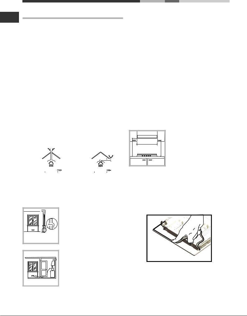
•Kitchen cabinets adjacent to the appliance and taller than the top of the hob must be at least 600 mm from the edge of the hob.
•Hoods must be installed according to their relative installation instruction manuals and at a minimum distance of 650 mm from the hob (see figure).
•Place the wall cabinets adjacent to the hood at a minimum height of 420 mm from the hob (see figure).
|
600mm min. |
650mmmin. |
420mmmin. |
If the hob is installed beneath a wall cabinet, the latter must be situated at a minimum of 700 mm above the hob.
Before the installation remove the grids and burners from the hob and turn it upside down, making sure you don’t damage the thermocouples and spark plugs.
Apply the seals that come with the appliance along the outer edges of the hob to prevent any passage of air, humidity and water (see Figure).
For proper application make sure the surfaces to be sealed are clean, dry and free of any grease/oil.
•The installation cavity should have the dimensions indicated in the figure.
Fastening hooks are provided, allowing you to fasten the hob to tops that are between 20 and 40 mm thick. To ensure the hob is securely fastened to the top, we recommend you use all the hooks provided.
PLEASE PHONE US TO REGISTER YOUR APPLIANCE AND ACTIVATE YOUR PARTS GUARANTEE ON 08448 24 24 24
4
 Loading...