

Istruzioni per l’uso
CAPPA
I
Italiano, 1
F
Français, 25
NL
Nederlands, 49
H562 IX
H562 WH
H562 BK
H572 IX
H592 IX
GB
English, 9
E
Español, 33
D
Deutsch, 17
P
Portoguês, 41
Sommario
I
Installazione, 2-3
Montaggio
Informazioni tecniche, 4
Collegamento elettrico
Dati tecnici
Descrizione, 5
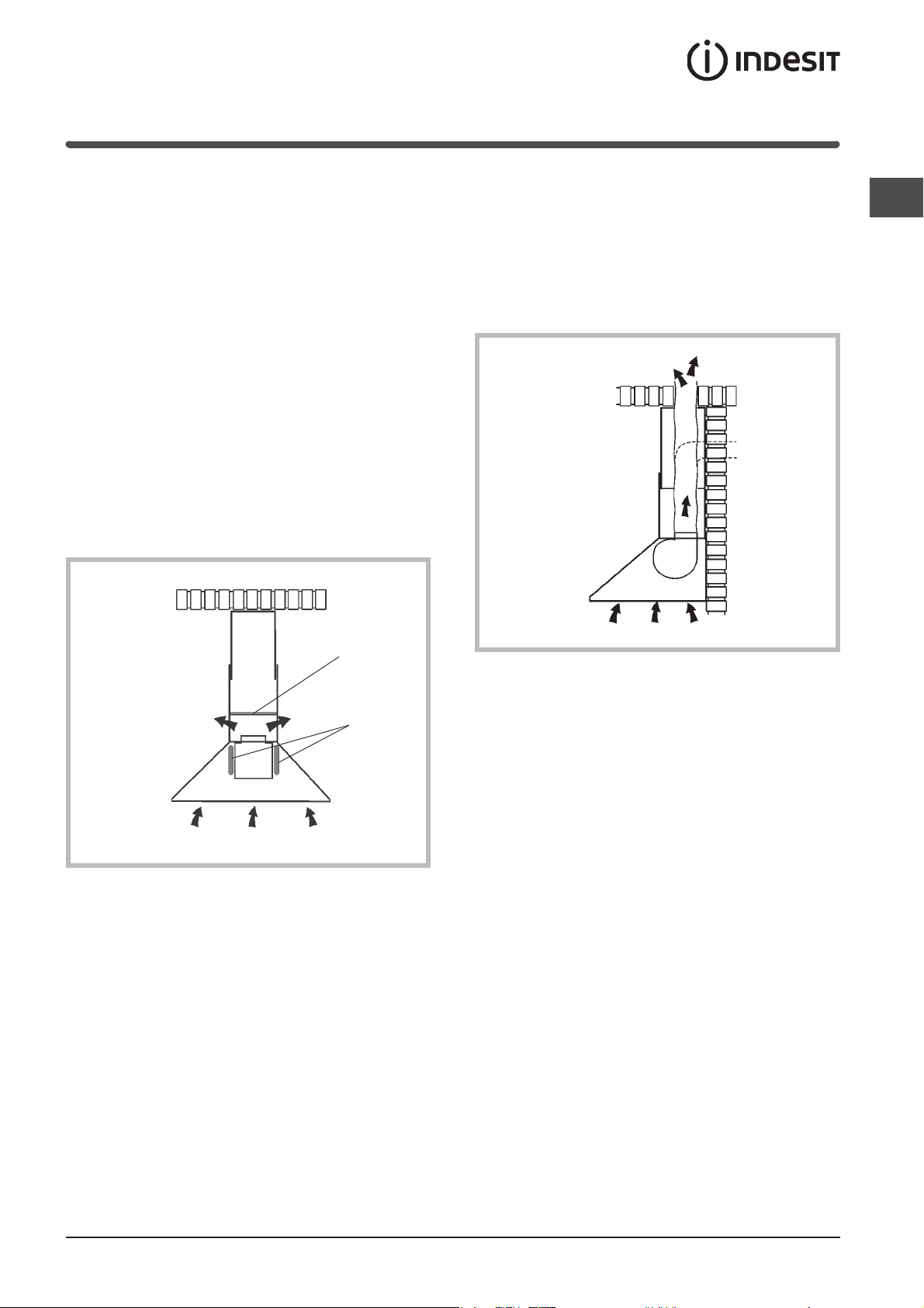
Versione filtrante
Versione aspirante
Funzionamento, 6
Comandi
Manutenzione, 7
Pulizia della cappa
Pulizia dei filtri antigrasso
Sostituzione dei filtri carbone
Sostituzione delle lampade
Precauzioni e consigli, 8
Sicurezza generale
Scarico dell’aria
Smaltimento
Installazione
Montaggio
I
Prima di procedere alle operazioni di montaggio,
per una più facile manovrabilità dell'apparecchio
disinserire la griglia metallica (per le istruzioni vedere
paragrafo “Pulizia del filtro antigrasso” sotto il capitolo “Manutenzione”).
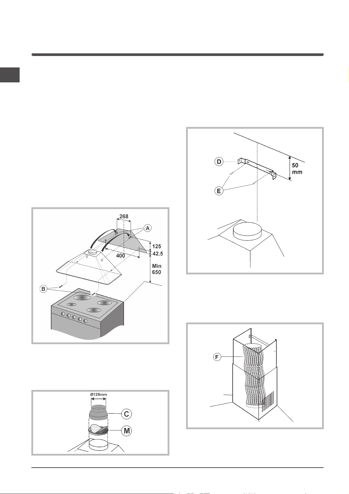
Fissaggio a muro
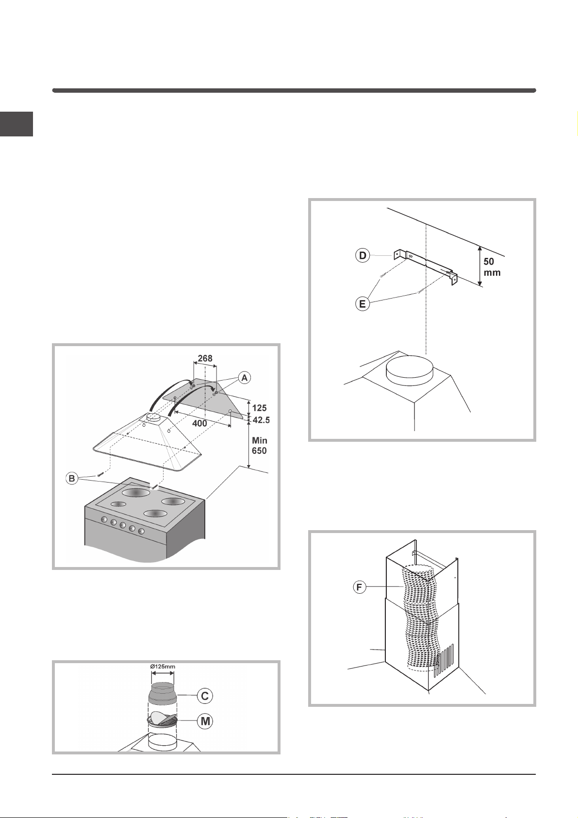
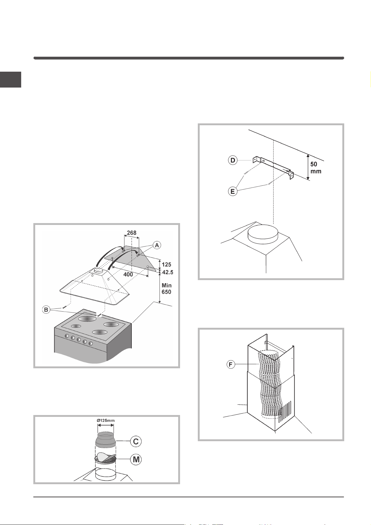
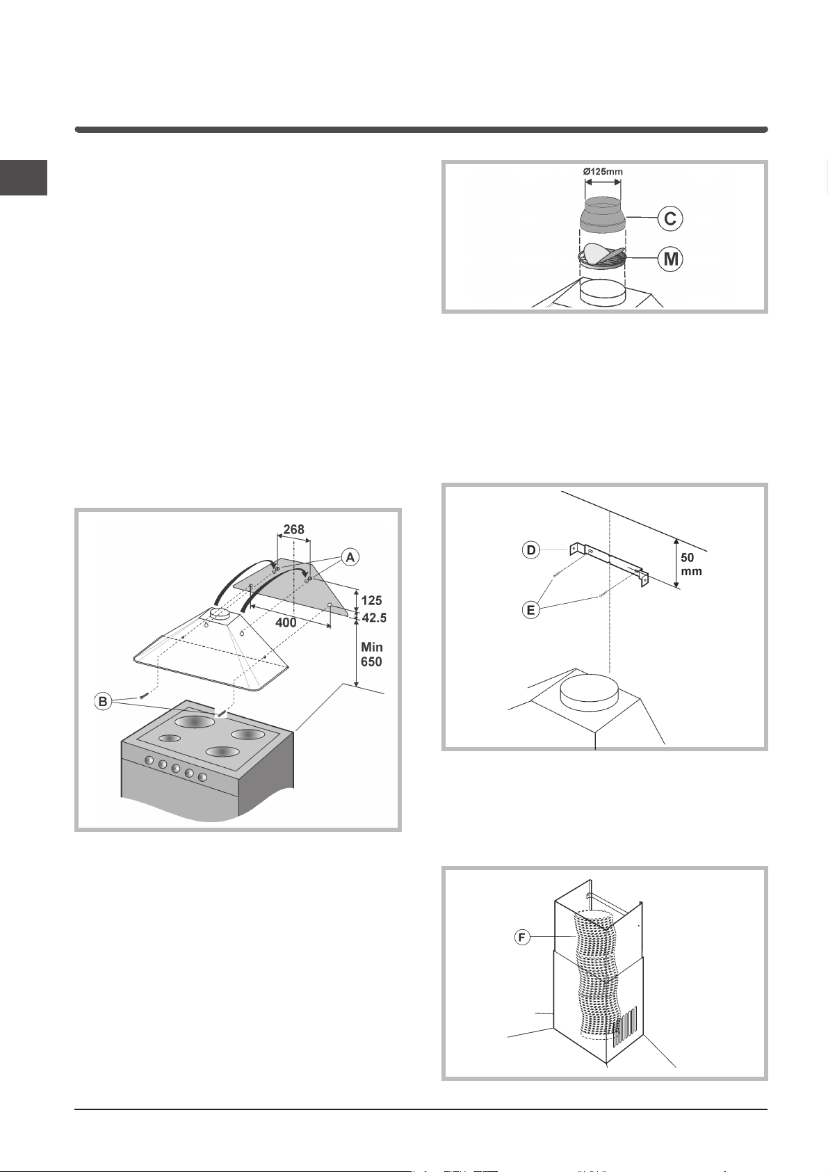
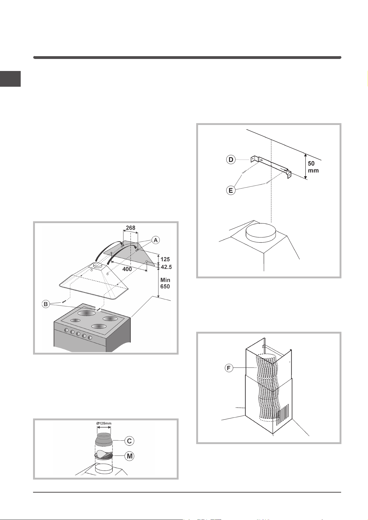
1) Tracciare sulla parete una linea, sulla verticale del
piano di cottura. Segnare sulla parete i 4 fori da
fare (fori A e fori B) rispettando le misure indicate
nella figura sotto.
2) Effettuare i fori (ø 8 mm) ed applicare i 4 tasselli in
dotazione.
3) Inserire solamente 2 viti, nei fori posti piu’ in alto
(A) ed agganciarvi la cappa.
4) Procedere al fissaggio definitivo inserendo altre 2
viti nei fori B.
Fissaggio del tubo decorativo
1) Appoggiare la staffa (D) a 50 mm dal soffitto
e posizionarla sulla verticale della cappa.
Con un pennarello segnare sulla parete i 2 fori;
effettuare i 2 fori ed inserire 2 tasselli.
2) Fissare la staffa alla parete mediante 2 viti (E).
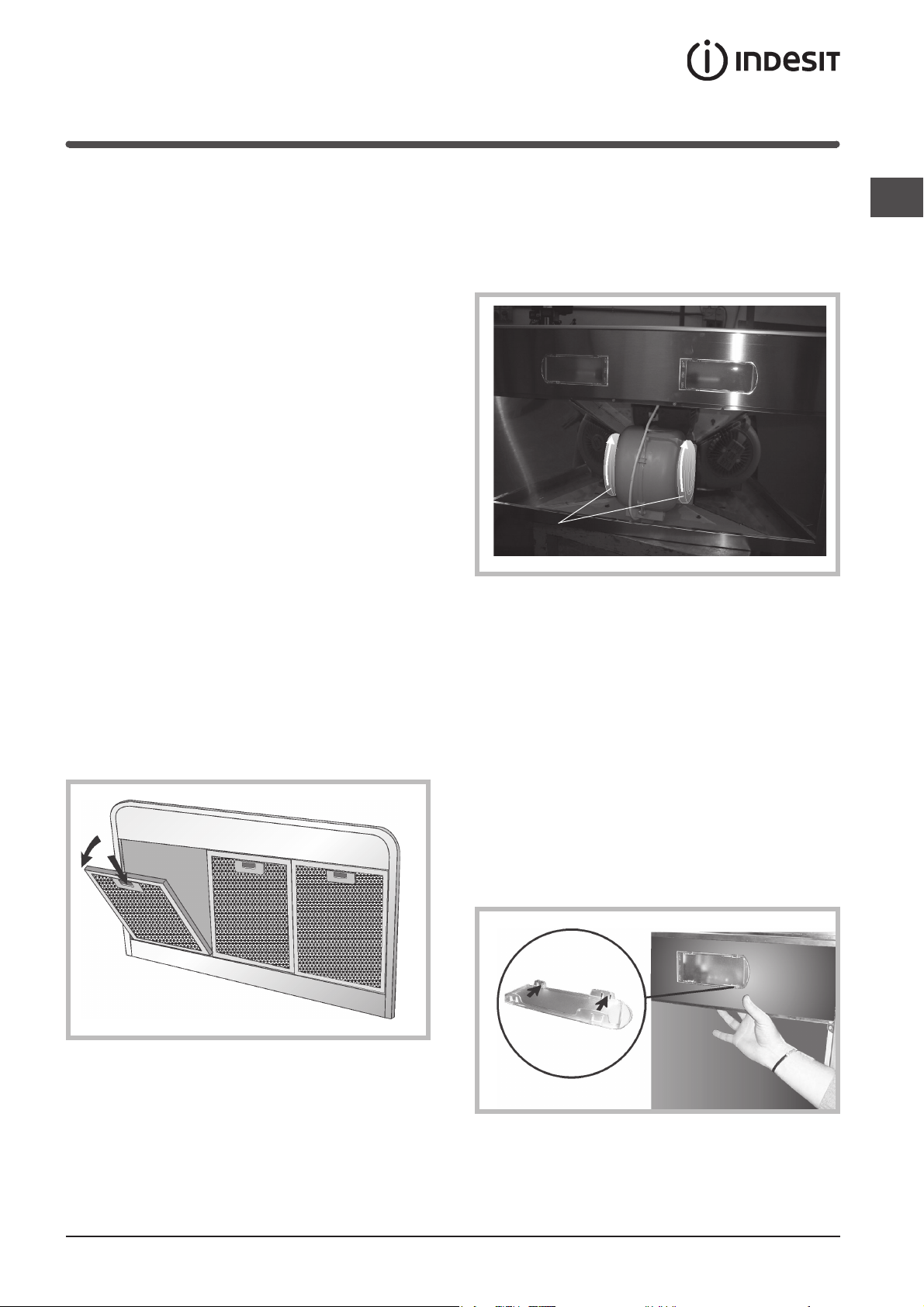
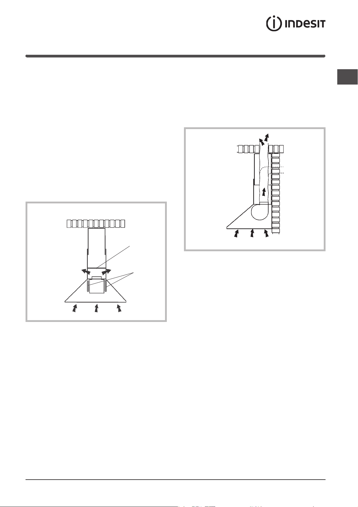
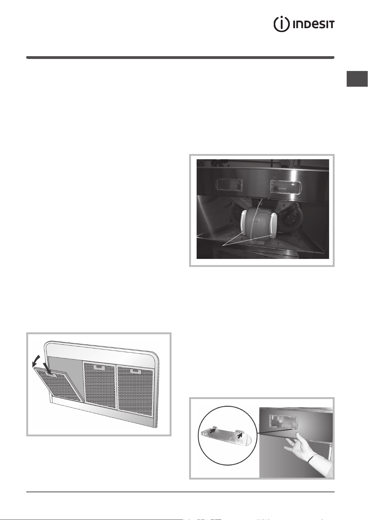
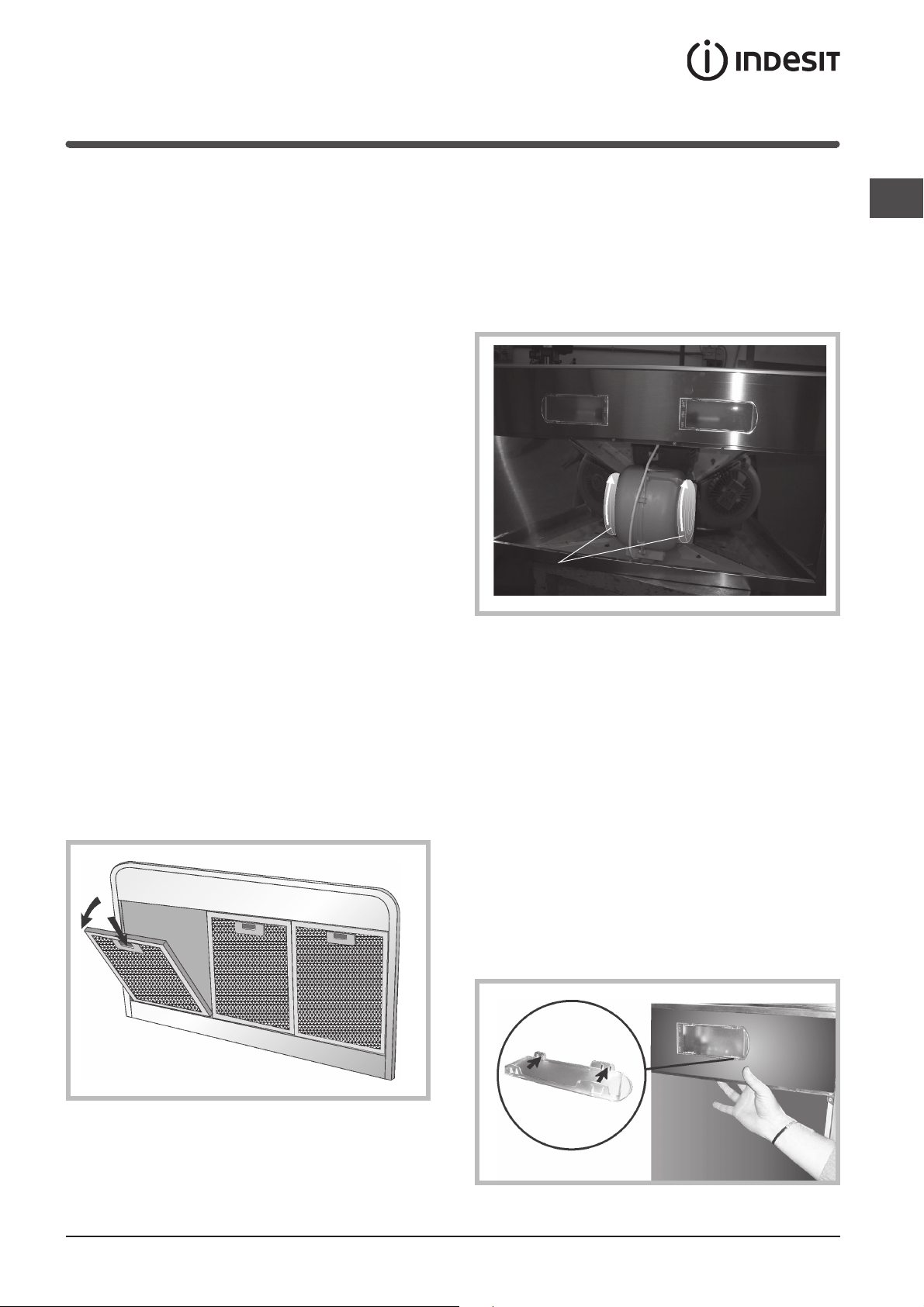
5) Solamente per le versioni aspiranti:
- posizionare la flangia (M) sopra la bocca uscita
aria del motore ed esercitare una leggera pressione.
- la bocca uscita aria della cappa ha diametro 150
mm; se si ha necessità di un diametro inferiore, si
puo’ montare la riduzione (C).
3) Solamente per le versioni aspiranti: collegare la
bocca uscita aria della cappa al foro di scarico
dell’aria, tramite un tubo flessibile (F) di diametro
150 mm. Bloccare il tubo flessibile con delle
fascette metalliche (tubo e fascette non sono in
dotazione).
2

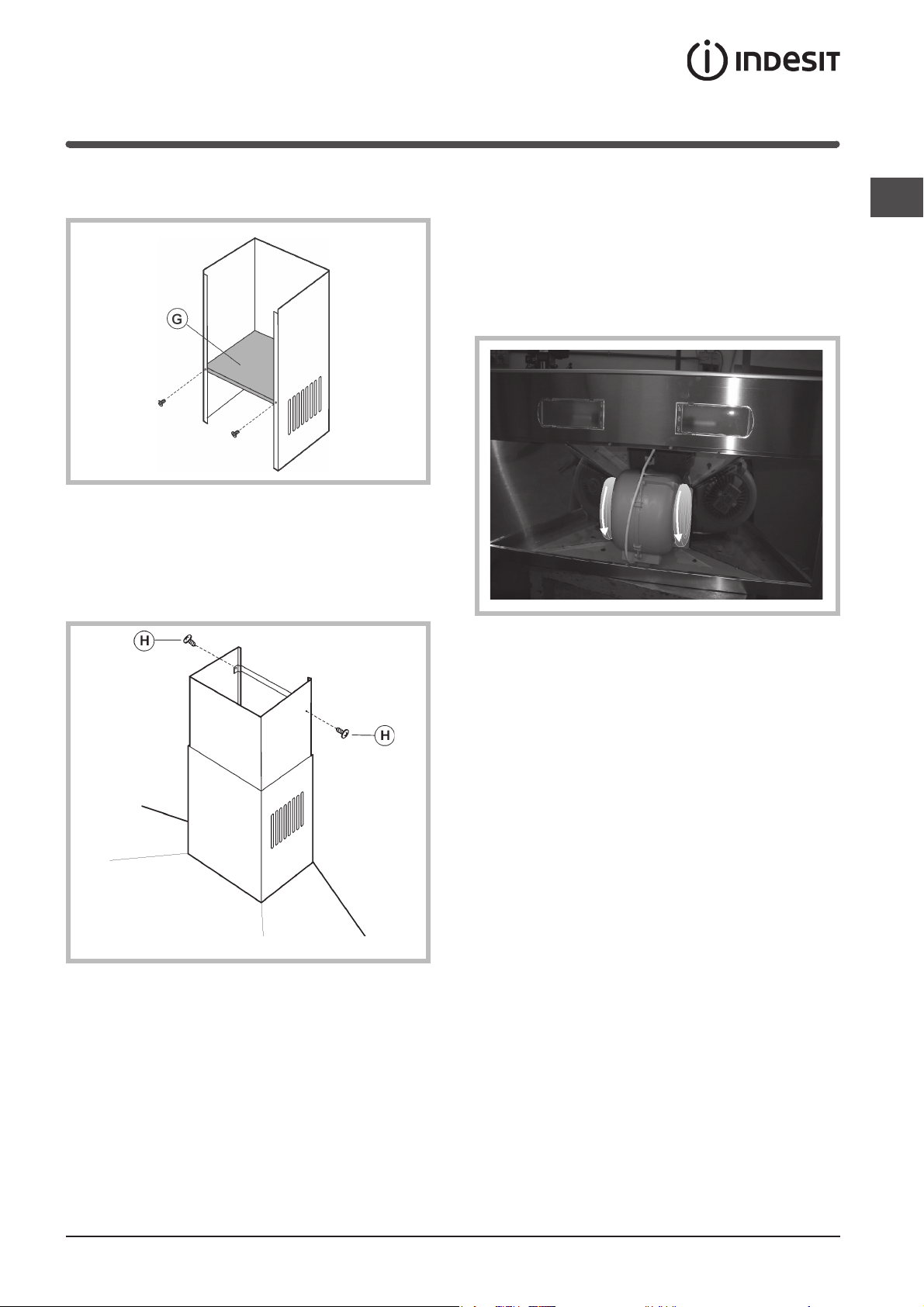
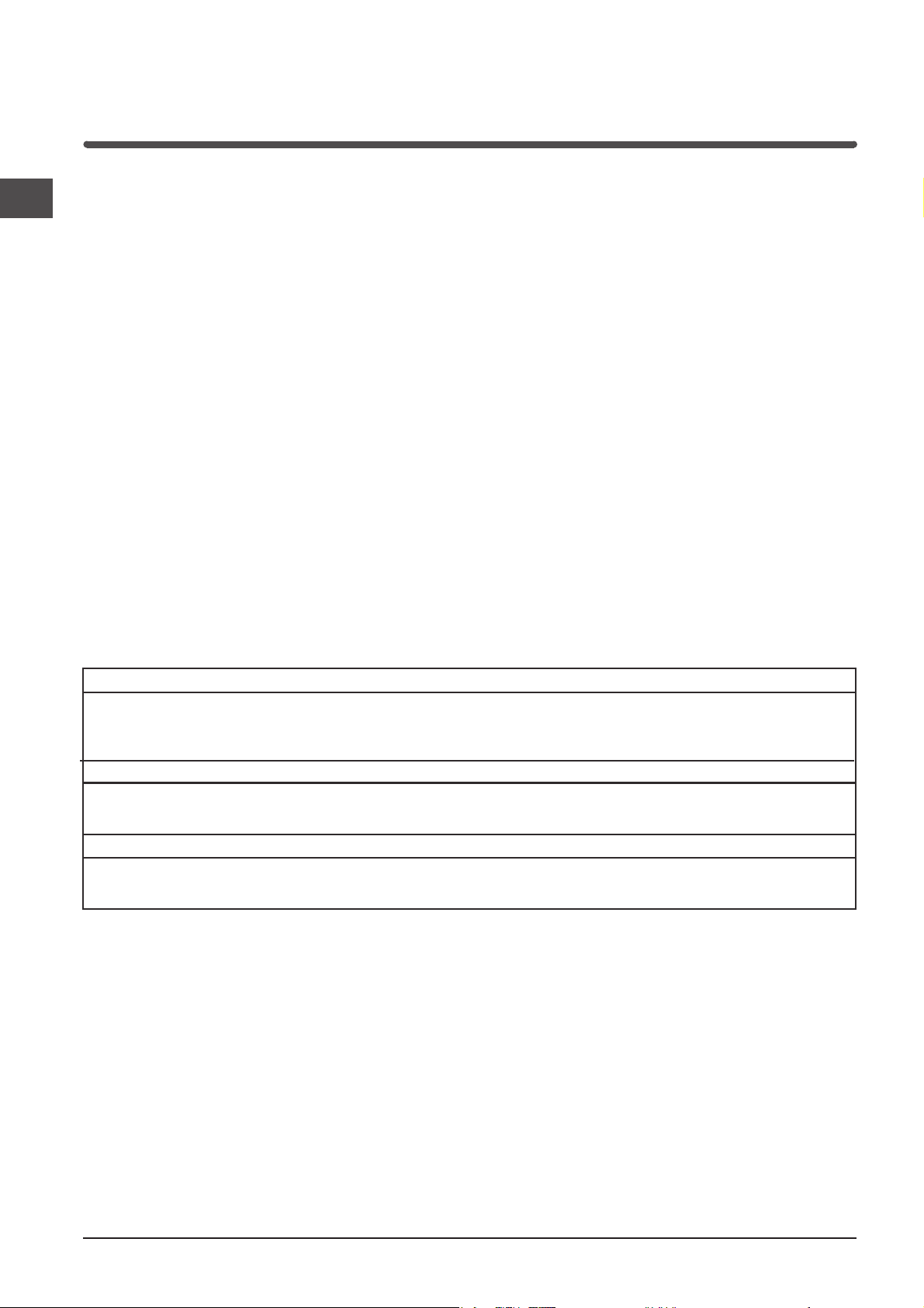
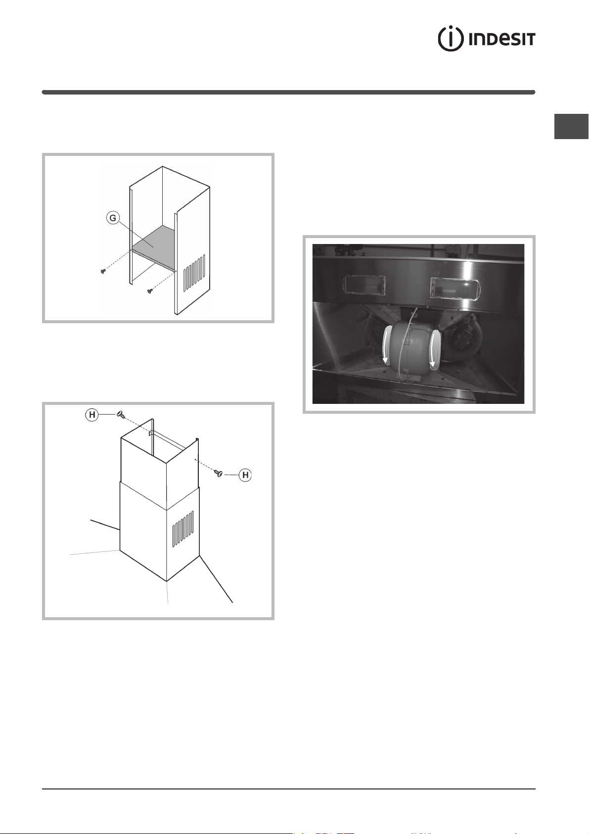
4) Solamente per le versioni filtranti: fissare il deflettore aria (G) al tubo inferiore utilizzando 2 viti.
5) Effettuare il collegamento elettrico della cappa
mediante il cavo di alimentazione (riferimento
paragrafo “Collegamento elettrico”).
6) Inserire il tubo decorativo appoggiandolo sulla
cappa; sollevare il tubo superiore fino al soffitto
e fissarlo tramite le 2 viti (H).
7) Solamente per le versioni filtranti;
nella versione filtrante è necessario l’uso del filtro/i
carbone, per cui, nel caso non sia già installato
nella cappa, montatelo/i come segue:
agganciate il filtro carbone con movimento rotatorio,
in senso anti-orario.
Nella versione aspirante il/i filtro/i al carbone non è
necessario, per cui se è già installato/i nella cappa
rimuovetelo/i.
I
3
Informazioni tecniche
Collegamento elettrico
I
! Predisporre l’alimentazione elettrica entro l’ingom-
bro del tubo decorativo.
! Nell’operazione di collegamento elettrico verificare
che i valori di tensione corrispondano con
quelli indicati nella targa inserita all’interno
dell’apparecchio.
! Se il Vostro apparecchio non è provvisto di cavo
flessibile non separabile e di spina, o di altro
dispositivo che assicuri la onnipolare disinserzione
dalla rete, con una distanza di apertura dei contatti
di almeno3 mm, allora tali dispositivi di separazione
dalla rete devono essere previsti nell'installazione
fissa.
! Se il Vostro apparecchio è provvisto di cavo
alimentazione e di spina, porre l'apparecchio
in modo che la spina sia accessibile.
Dati tecnici
Modello H562IX / H562WH / H562 BK H572IX H592IX
Dimensioni larghezza 59.8 cm larghezza 69.8 cm larghezza 89.8 cm
Peso lordo 12.7 Kg 14 Kg 16 Kg
Assorbimento Totale 330 W Totale 330 W Totale 330 W
Portata 770 m3/h 770 m3/h 770 m3/h
Filtro antigrasso
Superficie
di aspirazione 1487 cm
altezza 79 / 112 cm altezza 79 / 112 cm altezza 79 / 112 cm
profondità 50.7 cm profondità 50.7 cm profondità 50.7 cm
Ø del tubo di scarico 15 cm Ø del tubo di scarico 15 cm Ø del tubo di scarico 15 cm
Motore 1x250 W Motore 1x250 W Motore 1x250 W
Lampade 2x40 W Lampade 2x40 W Lampade 2x40 W
2
1487 cm
2
2287 cm
2
4
Descrizione
La cappa puo’ essere in versione filtrante o in versione
aspirante.
Decidere sin dall’inizio il tipo di installazione.
Per una maggiore efficienza, consigliamo di installare
la cappa in versione aspirante (se possibile).
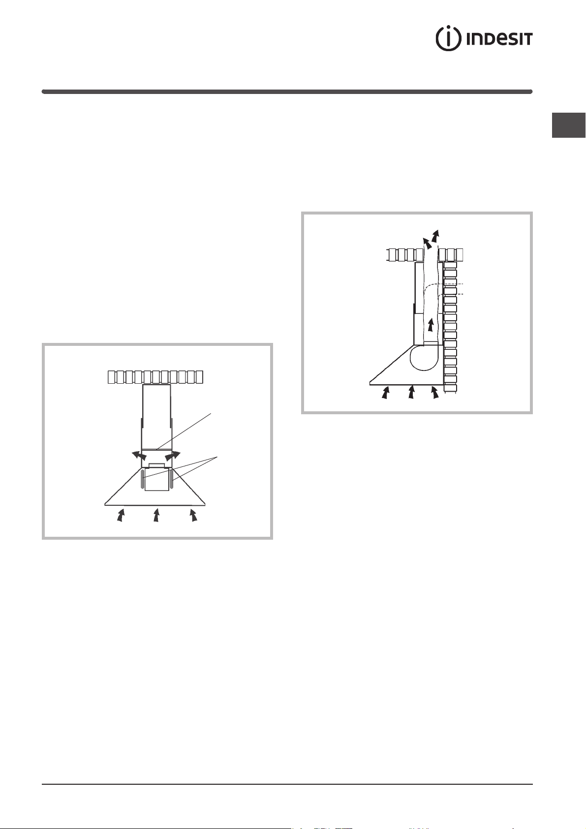
Versione filtrante
La cappa aspira l’aria della cucina impregnata di fumi
e di odori, depurandola attraverso il filtro anti-grasso
ed il filtro carbone per poi re-immetterla pulita
nella stanza.
Per questa versione è necessario un deflettore aria
(N) e 2 filtri al carbone (L).
Per una costante efficienza, è necessario sostituire
periodicamente i filtri al carbone.
Se la cappa non è dotata dei filtri al carbone,
richiederlo al rivenditore.
Versione aspirante
I
La cappa aspira l’aria della cucina impregnata di fumi
e di odori facendola passare attraverso il filtro
anti-grasso, poi la espelle all’esterno attraverso
un condotto di scarico.
In questa versione non è necessario utilizzare i filtri
al carbone.
N
L
5

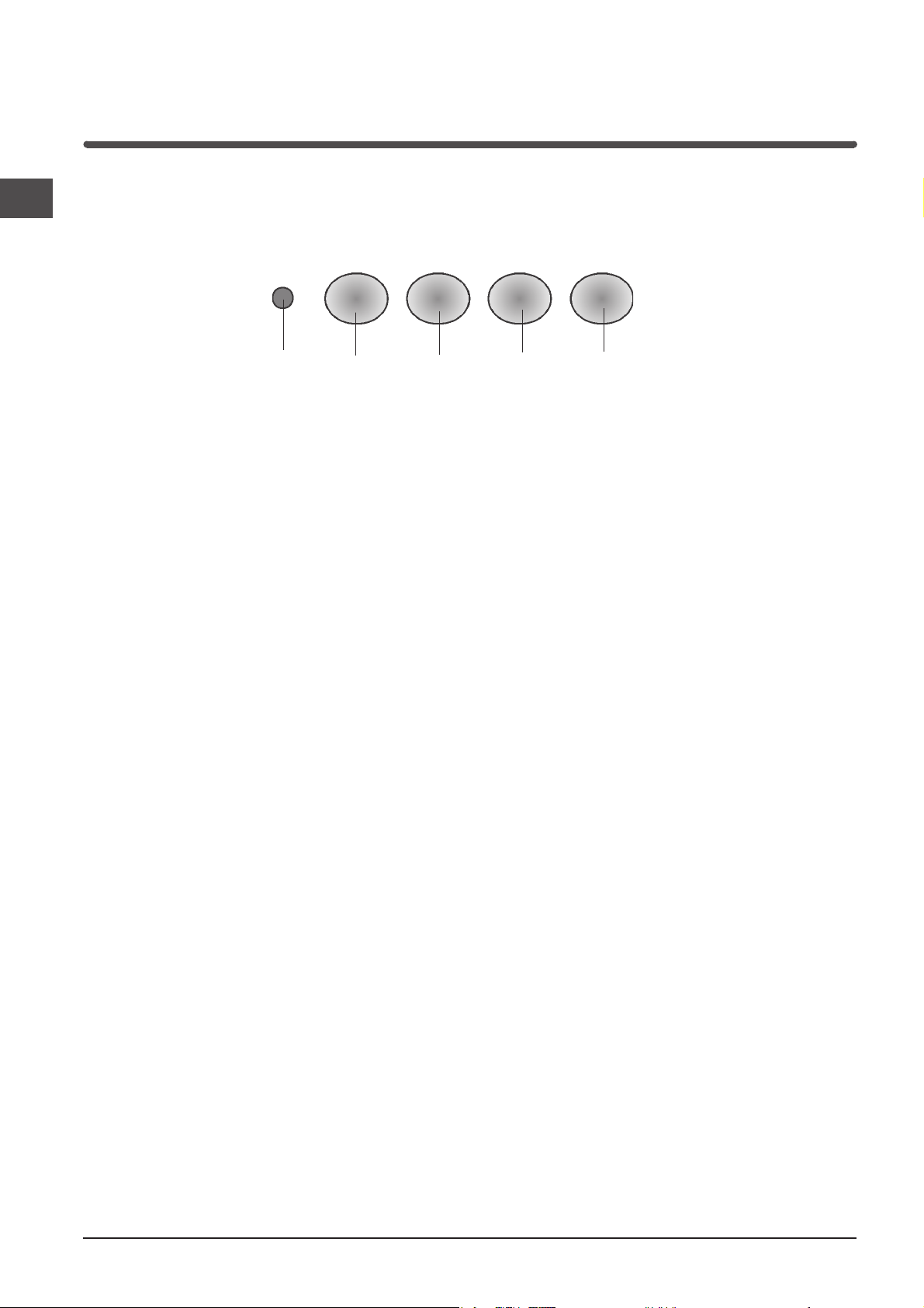
Funzionamento
Comandi
I
E
A - Tasto illuminazione
Accende / Spegne le luci.
B - Tasto ON/OFF motore
Attiva / Disattiva il motore.
Il motore si attiva alla prima velocità.
C - Tasto seconda velocità
Attiva / Disattiva il motore.
Aziona il motore alla 2
a
velocità
A
B
C
D - Tasto terza velocità
Attiva / Disattiva il motore.
Aziona il motore alla 3
E - Spia di funzionamento del motore
D
a
velocità
6
Manutenzione
! Prima di procedere a qualsiasi operazione di pulizia
o manutenzione è necessario togliere tensione.
! Per evitare un possibile rischio di incendio attenersi
alle istruzioni indicate per la pulizia dei filtri
antigrasso e la rimozione di eventuali depositi
di grasso sull’apparecchio.
Un'accurata manutenzione garantisce un buon funzionamento ed un buon rendimento nel tempo.
Pulizia della cappa
La rimozione di eventuali depositi di grasso
dall'apparecchio va effettuata periodicamente in
rapporto all'uso (almeno ogni 2 mesi).
Evitare l'uso di prodotti contenenti abrasivi o corrosivi.
Per la pulizia esterna di apparecchi verniciati adoperare
un panno inumidito con acqua tiepida e detersivo
neutro; per la pulizia esterna di apparecchi in acciaio,
rame od ottone è consigliato l'uso di prodotti specifici,
seguendo le istruzioni indicate sul prodotto;
per la pulizia interna dell'apparecchio usare
un panno/pennello imbevuto di alcool etilico
denaturato.
Sostituzione dei filtri carbone
I
Nel caso d'uso dell'apparecchio in versione filtrante,
sarà necessario sostituire i filtri al carbone (L).
Rimuovere i filtri carbone con movimento rotatorio, in
senso orario.
L
Sostituire i filtri carbone mediamente ogni 6 mesi,
in rapporto all'uso.
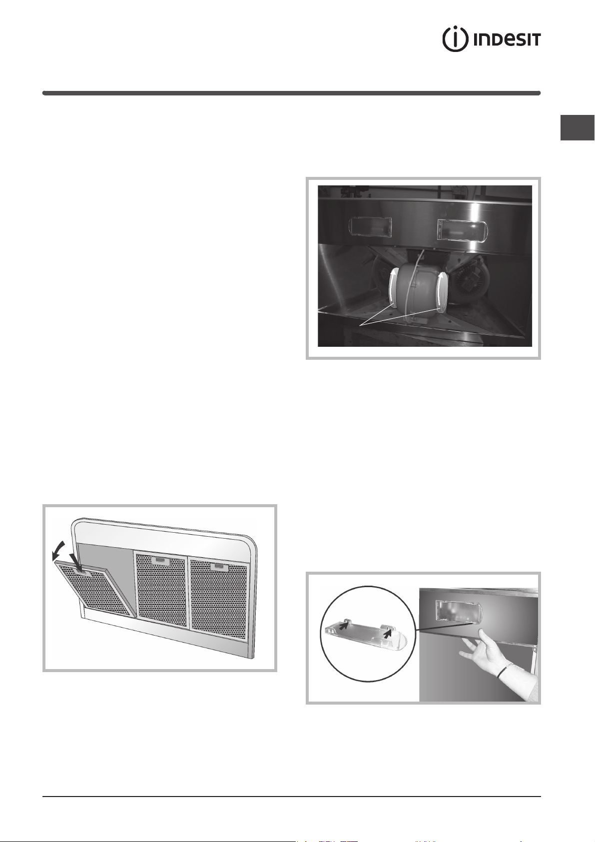
Pulizia dei filtri antigrasso
Per togliere i filtri antigrasso, in corrispondenza
della maniglia spingere il fermo verso l'interno e tirare
il filtro verso il basso.
Lavare i filtri con detersivo neutro a mano
o in lavastoviglie. Nel caso di lavaggio in lavastoglie,
un eventuale scolorimento non compromette in
nessun modo la funzionalità dei filtri.
Sostituzione delle lampade
Prestare particolare ATTENZIONE nell’effettuare
questa operazione, inoltre ricordare che è necessario
togliere la tensione.
Dopo aver tolto i filtri antigrasso, rimuovere la
plafoniera operando manualmente dall’interno della
cappa. Esercitare una leggera pressione sulla parte
mobile dei 2 fermi e sganciarla quindi dall’esterno.
Svitare la lampada e sostituirla con una lampada
dello stesso tipo.
Rimontare la plafoniera spingendola in sede dal lato
esterno.
Pulire i filtri antigrasso mediamente ogni 2 mesi, in
rapporto all'uso.
7

Precauzioni e consigli
Sicurezza generale
I
! La distanza minima tra la superficie di supporto
delle pentole sul piano di cottura e la parte inferiore
della cappa deve essere 65 cm. Se le istruzioni
per l’installazione del piano di cottura specificano
una distanza maggiore, questa deve essere tenuta
in considerazione.
! Questo apparecchio presenta accorgimenti
tecnici costruttivi tali da essere annoverato
nella classe di isolamento II e pertanto non
deve essere collegato a terra.
! Evitare l’uso di materiali che causano fiammate
(flambè) nelle immediate vicinanze dell’apparecchio.
! Nel caso di fritture fare particolarmente attenzione
al pericolo di incendio che costituiscono olio
e grassi. Particolarmente pericoloso per la
sua infiammabilità è l’olio già usato.
! Non usare griglie elettriche scoperte.
! Si raccomanda di non posizionare pesi eccessivi
sopra la cappa.
Scarico dell’aria
di calore. Pertanto attrezzare il locale con
delle prese d’aria che alimentino un flusso costante
di aria fresca.
Smaltimento
La direttiva Europea 2002/96/CE sui rifiuti di
apparecchiature elettriche ed elettroniche (RAEE),
prevede che gli elettrodomestici non debbano essere
smaltiti nel normale flusso dei rifiuti solidi urbani.
Gli apparecchi dismessi devono essere raccolti
separatamente per ottimizzare il tasso di recupero
e riciclaggio dei materiali che li compongono
ed impedire potenziali danni per la salute e l’ambiente.
Il simbolo del cestino barrato è riportato su tutti
i prodotti per ricordare gli obblighi di raccolta separata.
Per ulteriori informazioni, sulla corretta dismissione
degli elettrodomestici, i detentori potranno rivolgersi
al servizio pubblico preposto o ai rivenditori.
Se il vostro apparecchio deve essere istallato in
versione Aspirante, predisporre il foro ed il condotto di
scarico dell’aria.
Per ottenere condizioni ottimali nelle versioni aspiranti,
utilizzare un tubo per lo scarico dell’aria che abbia:
lunghezza minima indispensabile, minor numero
possibile di curve (angolo massimo della curva: 90°),
materiale approvato normativamente (a seconda dello
Stato), lato interno piú liscio possibile. Si consiglia
inoltre di evitare cambiamenti drastici di sezione del
tubo (diametro: 150 mm).
! L'aria raccolta non deve essere convogliata
in un condotto usato per lo scarico di fumi di
apparecchi alimentati con energia diversa da quella
elettrica (impianti di riscaldamento centralizzati,
termosifoni, scaldabagni ecc.).
! Per lo scarico dell'aria da evacuare rispettare
le prescrizioni delle autorità competenti.
Inoltre l'aria da scaricare non deve essere eliminata
attraverso una cavità del muro a meno che tale
cavità non sia destinata a questo scopo.
! Prevedere un'adeguata areazione del locale quando
una cappa e apparecchi alimentati con energia
diversa da quella elettrica (stufe a gas, ad olio,
a carbone ecc), vengono usati
contemporaneamente. Infatti la cappa aspirante
evacuando l'aria potrebbe creare una pressione
negativa nella stanza. La pressione negativa
del locale non deve superare i 0,04 mbar, evitando
così il risucchio dei gas di scarico della fonte
8
Instructions for use
HOOD
I
Italiano, 1
F
Français, 25
NL
Nederlands, 49
H562 IX
H562 WH
H562 BK
H572 IX
H592 IX
GB
English, 9
E
Español, 33
D
Deutsch, 17
P
Portoguês, 41
Contents
GB
Installation, 10-11
Assembly
Technical information, 12
Electrical connection
Technical data
Description, 13
Filtering version
Ducting version
Operation, 14
Controls
Maintenance,15
Cleaning the hood
Cleaning the grease filters
Replacing the charcoal filters
Replacing the lamps
Precautions and tips, 16
General safety
Air vent
Disposal
9
Installation
GB
Assembly
Before proceeding with the assembly operations,
remove the metal grille so that the hood is easier
to handle (for the instructions see the paragraph
“Cleaning the grease filter” in the chapter on
“Maintenance”).
Fixing to the wall
1) Draw a line on the wall along the vertical axis of
the hob. Mark the 4 holes (A and B) to be drilled
on the wall, respecting the measurements
indicated in the figure below.
2) Drill the holes (8 mm ø) and fit the 4 screw
anchors provided.
3) Fit only 2 screws in the topmost holes (A) and
hook the hood onto them.
4) Proceed with final fixing using a further 2 screws
in the holes (B).
Securing the decorative flue
1) Place the bracket (C) 50 mm from the ceiling and
position it on the vertical axis of the hood.
With a felt-tip pen, mark the 2 holes on the wall;
drill the 2 holes and fit 2 screw anchors.
2) Fix the bracket to the wall using 2 screws (E).
5) Only for the ducting versions:
- set the flange (M) over the motor and press
slightly.
- the air vent of the hood has a diameter of 150
mm; if you need a smaller diameter, fit the
reducer (C).
3) Only for the ducting versions: Connect the air vent
of the hood to the air vent hole using a flexible
hose (F) of 150 mm diameter. Lock the flexible
hose with some metal hose clamps (hose and
clamps not provided).
10
4) Only for filtering versions: Secure the air baffle (G)
to the lower flue using 2 screws.
5) Make the electrical connection of the hood by
means of the power cable (refer to the paragraph
“Electrical connection”).
6) Fit the decorative flue resting it on the hood Lift
the upper flue up to the ceiling and secure it by
means of the 2 screws (H).
7) Only for filtering versions;
One or more charcoal filters are required for the
filtering version. If they are not yet installed in the
hood, fit it/them as follows:
fit the charcoal filter by turning it anticlockwise.
The ducting version does not require the charcoal
filter/s, therefore, if already fitted in the hood remove
it/them.
GB
11
Technical information
GB
Electrical connection
! Arrange the electrical power supply within the
decorative flue dimensions.
! When making the electrical connections, check that
the voltage values correspond to those indicated on
the data plate inside the appliance itself.
! In case your appliance is not furnished with a non
separating flexible cable and has no plug, or has not
got any other device ensuring omnipolar
disconnection from the electricity main, with a
contact opening distance of at least 3 mm, such
separating device ensuring disconnection from the
main must be included in the fixed installation.
! If your unit features a power lead and plug, position
this so the plug is accessible.
! The following warning is valid in the United Kingdom
only (in case your cable is not furnished with a
plug). As the colours of the wires in the mains lead
of this appliance may not correspond with the
coloured markings identifying the terminals in your
plug, proceed as follows: – the wire which is
coloured blue must be connected to the terminal
which is marked with the letter N or coloured black;
– the wire which is coloured brown must be
connected to the terminal which is marked with the
letter L or coloured red.
– terminal of a three-pin plug.
Technical data
Model H562IX / H562WH / H562 BK H572IX H592IX
Dimensions width 59.8 cm width 69.8 cm width 89.8 cm
Gross weight 12.7 Kg 14 Kg 16 Kg
Absorption Total 330 W Total 330 W Total 330 W
Flow rate 770 m3/h 770 m3/h 770 m3/h
Grease filter
Suction
surface area 1487 cm
height 79 /112 cm height 79 /112 cm height 79 /112 cm
depth 50.7 cm depth 50.7 cm depth 50.7 cm
Outlet pipe diameter 15 cm Outlet pipe diameter 15 cm Outlet pipe diameter 15 cm
Motor 1x250 W Motor 1x250 W Motor 1x250 W
Lamps 2x40 W Lamps 2x40 W Lamps 2x40 W
2
1487 cm
2
2287 cm
2
12
Description
The hood may be in the filtering or ducting version.
Decide from the outset which type is to be installed.
For better efficiency, we recommend installing the
hood in the ducting version (if possible).
Filtering version
The hood aspirates air from the kitchen impregnated
with fumes and smells, purifies it through the grease
filter and the charcoal filter, and then circulates clean
air back into the room.
This version requires an air baffle (N) and 2 charcoal
filters (L).
In order to maintain constant efficiency, the charcoal
filters must periodically be replaced.
If the hood is not fitted with the charcoal filters,
request one from the dealer.
N
Ducting version
GB
The hood aspirates air from the kitchen impregnated
with fumes and smells, passes it through the grease
filter and then expels it to the outside through an
exhaust duct.
For this version the charcoal filters does not need to
be used.
L
13
Operation
GB
Controls
E
A - Light button
Turns the lights on/off.
B - Motor ON/OFF button
Activates/deactivates the motor.
The motor is activated at first speed.
C - Second speed button
Activates/deactivates the motor.
Activates the motor at second speed
A
B
C
D - Third speed button
Activates/deactivates the motor.
Activates the motor at third speed
E - Motor operation light
D
14
Maintenance
! Always switch off the electricity supply before
carrying out any cleaning or servicing operations
on the appliance.
! To avoid possible risks of fire always comply with
the indicated instructions when cleaning grease
filters and when removing grease deposits from
the appliance.
Careful maintenance will assure good functioning and
good efficiency over time.
Cleaning the hood
Any fat deposits should be removed from the
appliance periodically depending on amount of use (at
least every 2 months). Avoid using abrasive or
corrosive products. To clean painted appliances on
the outside, use a cloth dipped in lukewarm water and
neutral detergent. To clean steel, copper or brass
appliances on the outside, it is always best to use
specific products, following the instructions on the
products themselves. To clean the inside of the
appliance, use a cloth (or brush) dipped in denatured
ethyl alcohol.
Replacing the charcoal filters
GB
If using the hood in the filtering version, the charcoal
filters (L) will periodically have to be replaced.
Remove the charcoal filters by turning it clockwise.
L
Replace the charcoal filters on average every 6
months depending on how heavily the hood is used.
Replacing the lamps
Cleaning the grease filters
To remove the grease filters, push the catch near the
handle towards the inside and pull the filter
downwards.
Wash the filters by hand or in the dishwasher using
a neutral detergent. If they are washed
in the dishwasher, any loss of colour will
not jeopardise functioning of the filters in any way.
Pay particular ATTENTION when carrying out this
operation and remember to remove the voltage.
After having removed the grease filters, remove
the light fitting, operating manually from inside
the hood.
Apply light pressure to the mobile part of the 2
retainers and release it from the outside.
Unscrew the bulb and replace it with a bulb
of the same type.
Re-assemble the light fitting by pushing it into its
seat from the outside.
Clean the grease filters every 2 months on average
depending on how heavily the hood is used.
15
Precautions and tips
GB
General safety
! The distance between the supporting surface for
the cooking vessels on the hob and the lower part
of the hood must be at least 65 cm.
If the instructions for installation for the hob specify
a greater distance, this has to be taken into account.
! This appliance has such technical particulars
that it belongs to class II insulation, therefore
it must not be earthed.
! Avoid using materials which could cause spurts
of flame (flambées) near the appliance.
! When frying, take particular care to prevent oil
and grease from catching fire. Already used oil
is especially dangerous in this respect.
! Do not use uncovered electric grates.
! Do not place excessive weights above the hood.
Air vent
Should you install the ducting version, prepare the air
vent hole and duct.
In the Ducting version, to get optimal conditions the air
venting pipe should: be as short as possible, have the
lowest number of bends (max bende angle: 90°, be
made of material approved by local authorities
(according to the State), have its inner side as regular
and smooth as possible. It is moreover recommended
to avoid drastic changes of pipe cross section
(recommended diameter: 150 mm).
! The air collected must not be conveyed into a duct
used to blow off smokes from appliances fed with
an energy other than electricity (central heating
systems, thermosiphons, water-heaters, etc.).
! Comply with the official instructions provided by
the competent authorities in merit when installing
the disposal duct. In addition, exhaust air should
not be discharged into a wall cavity, unless
the cavity is designed for that purpose.
! The room must be well aerated in case a hood
and some other heat equipment fed with an energy
other than electricity (gas, oil, coal heaters, etc)
operate at the same time. In fact the ducting hood,
disposing of air, could create a vacuum in the room.
The vacuum should not exceed 0,04mbar.
This prevents the gas exhausted by the heat source
from being intaken again. It is therefore advisable
to ensure the room contains air taps able to ensure
a steady flow of fresh air.
Disposal
The European Directive 2002/96/EC on Waste
Electrical and Electronic Equipment (WEEE), requires
that old household electrical appliances must
not be disposed of in the normal unsorted municipal
waste stream.
Old appliances must be collected separately in order
to optimise the recovery and recycling of the materials
they contain and reduce the impact on human health
and the environment.
The crossed out “wheeled bin” symbol on the product
reminds you of your obligation, that when you dispose
of the appliance it must be separately collected.
Consumers should contact their local authority or
retailer for information concerning the correct disposal
of their old appliance.
16
Betriebsanleitung
ABZUGSHAUBE
I
Italiano, 1
F
Français, 25
NL
Nederlands, 49
H562 IX
H562 WH
H562 BK
H572 IX
H592 IX
GB
English, 9
E
Español, 33
D
Deutsch, 17
P
Portoguês, 41
Zusammenfassung
D
Installation, 18-19
Montage
Technische Informationen, 20
Elektroanschluss
Technische Daten
Beschreibung, 21
Umluftversion
Abluftversion
Betrieb, 22
Bedienung
Wartung, 23
Reinigung der Abzugshaube
Reinigung der Fettfilter
Austausch der Kohlefilter
Austausch der Lampen
Vorsichtsmaßnahmen und Hinweise, 24
Allgemeine Sicherheit
Abführung der Abluft
Entsorgung
17
Installation
D
Montage
Vor Beginn der Montagearbeiten
ist zur besseren Handhabung des Geräts das
Metallgitter herauszunehmen (Hinweise zur
Demontage siehe “Reinigung der Fettfilter” im
Kapitel “Wartung”).
Wandmontage
1) An der Wand eine vertikale Linie bezogen auf die
Kochfläche markieren. Die 4 erforderlichen
Bohrlöcher (Löcher A und B) mit den in
nachstehender Abbildung angegebenen
Abmessungen an der Wand markieren.
2) Löcher (ø 8 mm) bohren und die 4 im Lieferumfang
enthaltenen Dübel einsetzen.
3) Nur 2 Schrauben in die beiden oberen Löcher (A)
einsetzen und die Haube einhängen.
4) Endgültige Befestigung durch Einsetzen der
übrigen beiden Schrauben (B) vornehmen.
Befestigung des Zierrohres
1) Den Bügel (D) im Abstand von 50 mm von der
Decke auf der Vertikalen der Haube positionieren.
Mit einem Filzstift die 2 Löcher an der Wand
markieren, die beiden Löcher bohren und die 2
Dübel einsetzen.
2) Den Bügel mit 2 Schrauben (E) an der Wand
befestigen.
5) Nur für Abluftversionen:
- den Flansch (M) über dem Luftauslass des
Motors positionieren und einen leichten Druck
ausüben
- Die Luftauslassöffnung der Haube hat den
Durchmesser 150 mm; falls ein kleinerer
Durchmesser benötigt wird, kann das
Reduktionsstück (C) eingesetzt werden.
18
3) Nur für Abluftversionen: Die Luftauslassöffnung
der Haube mit einem flexiblenRohr (F) mit 150 mm
Durchmesser an das Abzugsloch anschließen.
Das flexible Rohrstück mit Metallschellen
befestigen (Rohr und Schellen werden nicht
mitgeliefert).

4) Nur für Umluftversionen: Den Luftabweiser (G) mit
2 Schrauben am unteren Rohr befestigen.
5) Den Stromanschluss der Haube mit Hilfe des
Netzkabels (siehe Abschnitt “Elektroanschluss”)
vornehmen.
6) Das Zierrohr zum Einsetzen zunächst auf die
Haube legen, das obere Rohr bis zur Decke
anheben und mit den 2 Schrauben (H) befestigen.
7) Nur für Umluftversionen;
In der Umluftversion muß /muessen der/die Kohlefilter
eingebaut werden. Wenn die Haube keinen Umluftfilter
schon installiert hat, muß /muessen der/die Kohlefilter
wie es folgt, installiert oder entfernt werden: der/die
Kohlefilter durch eine Drehbewegung entgegen dem
Uhrzeigersinn einsetzen.
Deshalb wird/werden der/die Kohlefilter entfernt, wenn
sie in der Kappe angebracht sein sollten.
D
19

Technische Informationen
D
! Der Netzanschluss muss innerhalb des Umrisses
des Zierrohres vorgenommen werden.
! Beim elektrischen Anschluss muss überprüft
werden, ob die Spannungswerte des Stromnetzes
mit den Werten auf dem im Innern des Gerätes
angebrachten Typenschilds übereinstimmen.
! Falls Ihr Gerät nicht mit einem fest
angeschlossenem Kabel mit Stecker oder einer
sonstigen Vorrichtung, die eine allpolige
Unterbrechung mit einer Kontaktöffnung von
mindestens 3 mm versehen ist, so müssen die
entsprechenden Trennvorrichtungen bei der festen
Installation vorgesehen werden.
! Das Gerät so aufstellen, dass der Stecker
zugänglich ist, falls Ihr Gerät mit einem Netzkabel
mit Stecker ausgestattet ist.
Technische Daten
Modell H562IX / H562WH / H562 BK H572IX H592IX
Elektroanschluss
Abmessungen Breite 59.8 cm Breite 69.8 cm Breite 89.8 cm
Bruttogewicht 12.7 Kg 14 Kg 16 Kg
Stromaufnahme Insgesamt 330 W Insgesamt 330 W Insgesamt 330 W
Durchsatzleistung 770 m3/h 770 m3/h 770 m3/h
Fettfilter
Ansaugfläche 1487 cm
Höhe 79 / 112 cm Höhe 79 / 112 cm Höhe 79 / 112 cm
Tiefe 50.7 cm Tiefe 50.7 cm Tiefe 50.7 cm
Ø des Abluftrohres 15 cm Ø des Abluftrohres 15 cm Ø des Abluftrohres 15 cm
Motor 1x250 W Motor 1x250 W Motor 1x250 W
Lampen 2x40 W Lampen 2x40 W Lampen 2x40 W
2
1487 cm
2
2287 cm
2
20

Beschreibung
Die Dunsthaube kann als Abluft- oder Umluftversion
installiert werden.
Entscheiden Sie vor der Installation, welche Version
Sie wünschen (Umluft- oder Abluftversion).
Zur Verbesserung der Effizienz raten wir, die Haube
(sofern möglich) als Abluftversion zu installieren.
Umluftversion
Die Dunsthaube saugt Rauch und Küchendünste aus
der Küche ab, reinigt die Luft über der Fettfilter
und den Aktivkohlefilter und leitet die Luft nschließend
wieder in Raum zurück.
Für diese Version sind eine Umluftweiche (N) und 2
Aktivkohlefilter (L) erforderlich.
Zur Verbesserung der Effizienz muss der
aktivkohlefilter regelmäßig ausgetauscht werden.
Falls die Dunsthaube nicht mit Aktivkohlefilter
ausgestattet ist, fordern Sie diesen bei Ihrem Händler
an.
Abluftversion
D
Die Dunsthaube saugt Rauch und Küchendünste aus
der Küche ab, und Gerüche, indem diese durch der
Fettfilter geleitet und anschließend durch den
Abluftkanal ausgestoßen wird.
Bei dieser Version braucht kein Aktivkohlefilter
verwendet zu werden.
N
L
21

Betrieb
D
Bedienung
E
A - Beleuchtungstaste
Ein- / Ausschaltung der Beleuchtung.
B - Taste Motor ON/OFF
Ein- und Ausschaltung des Motors.
Der Motor läuft auf der ersten Geschwindigkeitsstufe
an.
C - Taste zweite Geschwindigkeitsstufe
Ein- und Ausschaltung des Motors.
Schaltet den Motor auf Geschwindigkeitsstufe
A
2
:
B
C
D - Taste dritte Geschwindigkeitsstufe
Ein- und Ausschaltung des Motors.
Schaltet den Motor auf Geschwindigkeitsstufe
E - Kontrollleuchte Motorbetrieb
D
3
:
22

Wartung
! Vor jeder Reinigungs- oder Wartungsarbeit muss
das Gerät vom Stromnetz getrennt werden.
! Zur Vermeidung einer möglichen Brandgefahr die
Anweisungen zur Reinigung der Fettfilter und zur
Entfernung eventueller Fettablagerungen auf dem
Gerät beachten.
Regelmäßig ausgeführte Wartungsmaßnahmen
sorgen für die Erhaltung der Funktionstüchtigkeit und
Leistungsfähigkeit des Geräts.
Reinigung der Abzugshaube
Die Entfernung eventueller Fettablagerungen vom
Gerät erfolgt in regelmäßigen Abständen in
Abhängigkeit von der Benutzung (zumindest alle zwei
Monate). Die Verwendung von scheuernden oder
korrosiven Produkten vermeiden. Für die äußere
Reinigung von lackierten Geräten ein mit lauwarmen
Wasser und Neutralreiniger angefeuchtetes Tuch
verwenden; für die äußere Reinigung der Geräte aus
Stahl, Kupfer und Messing wird die Verwendung von
Spezialprodukten empfohlen, wobei die auf dem
Produkte angegebenen Anweisungen zu beachten
sind; für die innere Reinigung der Geräte einen in
denaturalisierten Äthylalkohol eingetauchten Lappen
(oder Pinsel) verwenden.
Fettfilter - je nach Gebrauch - im Durchschnitt alle 2
Monate reinigen.
Austausch der Kohlefilter
Bei Gebrauch eines Geräts mit Umluftversion muss
der Kohlefilter ausgetauscht werden (L).
Der Kohlefilter durch eine Drehbewegung im
Uhrzeigersinn entfernen.
L
Der Kohlefilter ist - je nach Gebrauch - im
Durchschnitt alle 6 Monate auszutauschen.
D
Reinigung der Fettfilter
Zur Demontage der Fettfilter Klemme im Bereich des
Griffes nach innen drücken und Filter nach unten
ziehen.
Die Filter mit neutralem Reinigungsmittel oder in der
Waschmaschine waschen. Durch einen eventuellen
Farbverlust bei Gebrauch der Waschmaschine wird
die Wirkung der Filter in keiner Weise beeinträchtigt.
Austausch der Lampen
Bei diesem Eingriff besondere VORSICHT walten
lassen; außerdem den Strom abziehen.
Nachdem die Fettfilter entfernt sind, den Deckel im
Innern der Haube mit der Hand abheben.
Das bewegliche Teil der 2 Sperren mit leichtem
Druck aus der Einfassung lösen.
Die Glühlampe herausschrauben und durch eine
Lampe desselben Typs ersetzen.
Den Deckel durch leichten Druck wieder auf seiner
alten Position anbringen.
23

Vorsichtsmaßnahmen und Hinweise
D
Allgemeine Sicherheit
! Der Mindestabstand zwischen der Topf-
Trägerfläche auf der Kochmulde und dem unteren
Teil der Abzughaube muss 65 cm betragen. Geben
die Installationsanleitungen der Kochmulde einen
höheren Abstand an, so ist dieser einzuhalten.
! Dieses Gerät weist konstruktive technische
Details auf, die unter die Isolierungsklasse II
fallen und deshalb muss es nicht geerdet
werden.
! In der unmittelbaren Nähe des Geräts die
Benutzung von flammenerzeugenden Materialien
(Flambieren) vermeiden.
! Beim Frittieren besonders auf die Brandgefahr
achten, die durch Öl und Fette verursacht wird.
Besonders gefährlich ist die Entflammbarkeit von
bereits benutztem Öl.
! Keine offenen Elektrogrills verwenden.
! Es ist nicht empfehlenswert, Gegenstände mit
hohem Gewicht auf der Haube anzubringen.
Abführung der Abluft
Wenn das Gerät als Abluftversion installiert wird, ist
dafür zu sorgen, dass das hierfür erforderliche Loch
und der Abluftkanal vorhanden sind.
Um die bestmöglichsten Vorbedingungen zu erreichen,
ist es zu empfehlen, bei Abluftversionen Abluftrohre mit
folgenden Eigenschaften zu verwenden: möglichst
kurzgehaltene Länge und, die geringste Anzahl von
Kurven (Maximalwinkel der Kurve= 90 Grad), es
müssen normengerechte (je nach Staat) Materialien
verwendet werden, Innenseite möglichst glatt.
Ausserdem ist es ratsam, drastische Veränderungen
des Rohrquerschmittes zu vermeiden (empfohlener
Durchmesser: 150 mm).
! Ein Anschluss der Abluftleitungen an
Verbrennungsabgaskamine (zum Beispiel
Zentralheizung, Heizgeräte, Badezimmer-öfen usw.)
ist nicht gestattet.
! In jedem Fall sind bei der Ableitung der Abluft die
behördlichen Vorschriften zu beachten. Desweiteren
darf die Abluft nur dann durch ein Loch in der Wand
geleitet werden, wenn dieses für diesen Zweck
bestimmt ist.
! Achtung! Bei gleichzeitigem Betrieb einer Abluft-
Dunstabzugshaube und einer raumluftabhängigen
Feuerstätte (wie z. B. gas-, öl- oder kohlebetriebene
Heizgeräte, Durchlauferhitzer,
Warmwasserbereiter) ist Vorsicht geboten, da
beim Absaugen der Luft durch die
Dunstabzugshaube dem Aufstellraum die Luft
entnommen wird, die die Feuerstätte zur
Verbrennung benötigt. Ein gefahrloser Betrieb ist
möglich, wenn bei gleichzeitigem Betrieb von Haube
und raumluftabhängiger Feuerstätte im Aufstellraum der Feuerstätte ein Unterdruck von höchstens
0,04 mbar erreicht wird und damit ein Rücksaugen
der Feuerstättenabgase vermieden wird. Daher den
Raum mit Lüftungsanschlüssen versehen, die einen
konstanten Zustrom von Frischluft gewährleisten.
Entsorgung
Gemäß der Europäischen Richtlinie 2002/96/EC über
Elektro- und Elektronik-Altgeräte (WEEE) dürfen
Elektrohaushalts-Altgeräte nicht über den
herkömmlichen Haushaltsmüllkreislauf entsorgt
werden. Altgeräte müssen separat gesammelt werden,
um die Wiederverwertung und das Recycling der
beinhalteten Materialien zu optimieren und die
Einflüsse auf die Umwelt und die Gesundheit zu
reduzieren. Das Symbol „durchgestrichene Mülltonne“
auf jedem Produkt erinnert Sie an Ihre Verpflichtung,
dass Elektrohaushaltsgeräte gesondert entsorgt
werden müssen. Endverbraucher können sich an
Abfallämter der Gemeinden wenden, um mehr
Informationen über die korrekte Entsorgung ihrer
Elektrohaushaltsgeräte zu erhalten.
24

Mode d’emploi
HOTTE
I
Italiano, 1
F
Français, 25
NL
Nederlands, 49
H562 IX
H562 WH
H562 BK
H572 IX
H592 IX
GB
English, 9
E
Español, 33
D
Deutsch, 17
P
Portoguês, 41
Sommaire
F
Installation, 26-27
Montage
Informations techniques, 28
Branchement électrique
Caractéristiques techniques
Description, 29
Version filtrante
Version aspirante
Fonctionnement, 30
Commandes
Maintenance, 31
Nettoyage de la hotte
Nettoyage des filtres à graisse
Remplacement des filtres à charbon
Remplacement des ampoules
Précautions et conseils, 32
Sécurité générale
Evacuation de l’air
Elimination
25
Installation
F
Montage
Avant de procéder aux opérations de montage,
et pour une plus grande capacité de manoeuvre de
l’appareil, dégager la grille métallique (voir les
instructions au paragraphe “Nettoyage du filtre à
graisse” dans le chapitre “Maintenance”).
Fixation au mur
1) Tracer une ligne verticale par rapport au plan de
cuisson sur le mur. Sur la paroi, marquer les 4
trous à faire (trous A et trous B) en observant les
mesures indiquées dans la figure ci-dessous.
2) Faire les trous (ø 8 mm) et placer les 4 goujons
prévus à cet effet.
3) Ne placer que 2 vis dans les trous situés plus haut
(A) et y accrocher la hotte.
4) Procéder ensuite à la fixation définitive en plaçant
2 autres vis dans les trous B.
Fixation du tuyau télescopique
1) Placer la bride (D) à 50 mm du plafond
et la mettre à la verticale par rapport à la hotte.
Marquer les 2 trous sur le mur au moyen d’un stylo
de marquage ; faire 2 trous et placer les goujons.
2) Fixer la bride au mur au moyen de 2 vis (E).
5) Pour les versions aspirantes seulement :
- positionner la flange (M) au-dessus de la bouche
de sortie d’air du moteur et exercer une légère
pression.
- la bouche de refoulement d’air de la hotte a un
diamètre de 150 mm ; si un diamètre inférieur est
requis, on pourra monter le dispositif de réduction
(C).
3) Pour les versions aspirantes seulement: raccorder
la bouche de refoulement d’air de la hotte au trou
d’échappement au moyen d’un tuyau flexible (F)
d’un diamètre de 150 mm. Bloquer le flexible au
moyen de bandes métalliques (ni le tuyau, ni les
bandes ne sont prévus).
26

4) Pour les versions filtrantes seulement : Fixer le
déflecteur d’air (G) au tuyau inférieur au moyen de
2 vis.
5) Faire le raccordement électrique de la hotte au
moyen du câble d’alimentation (voir le paragraphe
“Branchement électrique”).
6) Placer le tube décoratif en le posant sur la hotte;
Soulever le tube supérieur jusqu’à hauteur du
plafond et le fixer avec les 2 vis (H).
7) Pour les versions filtrantes seulement;
sur la version recyclage, il est nécessaire d’utiliser
le ou les filtres à charbon, aussi dans le cas où il(s)
ne serai(en)t pas encore installé(s) dans la hotte,
le(s) monter comme suit,:
fixer le filtre à charbon par un mouvement de rotation
dans le sens contraire des aiguilles d’une montre.
Sur la version aspirante, le ou les filtres à charbon
n’est/ne sont pas nécessaires, aussi dans le cas où
il(s) serai(en)t installé(s) dans la hotte, le/les en retirer.
F
27

Informations techniques
F
! Installer l’alimentation électrique dans
l’encombrement du tuyau décoratif.
! Lors du raccordement électrique assurez-vous que
les valeurs de tension correspon-dent à celles qui
sont indiquées sur la plaque des caractéristiques de
l’appareil, qui se trouve à l'intérieur de celui-ci.
! Si votre appareil, n'a pas de câble flexible qui ne
peut pas être séparé ni de prise, ou bien d'autre
dispositif qui garantisse le dé-branchement de tous
les pôles du réseau, avec une distance d'ouverture
entre les contacts d'au moins 3 mm, ces dispositifs
de séparation du réseau doivent alors être prévus
dans l'installation fixe.
! Si votre appareil est muni d’un câble d’alimentation,
positionner l’appareil de manière à ce que la fiche
soit accessible.
Caractéristiques techniques
Modèle H562IX / H562WH / H562 BK H572IX H592IX
Branchement électrique
Dimensions largeur 59.8 cm largeur 69.8 cm largeur 89.8 cm
Poids brut 12.7 Kg 14 Kg 16 Kg
Courant absorbé Total 330 W Total 330 W Total 330 W
Portée 770 m3/h 770 m3/h 770 m3/h
Filtre à graisse
Surface
d’aspiration 1487 cm
hauteur 79 / 112 cm hauteur 79 / 112 cm hauteur 79 / 112 cm
profondeur 50.7 cm profondeur 50.7 cm profondeur 50.7 cm
Ødu tuyau d’évacuation 15cm Ødu tuyau d’évacuation 15cm Ødu tuyau d’évacuation 15cm
Moteur 1x250 W Moteur 1x250 W Moteur 1x250 W
Ampoules 2x40 W Ampoules 2x40 W Ampoules 2x40 W
2
1487 cm
2
2287 cm
2
28
Description
La hotte peut être installée en version filtrante ou en
version aspirante.
Vous devez décider, dès le début, le type
d’installation.
Pour une plus grande efficacité, nous conseillons
d’installer la hotte en version aspirante (si possible).
Version filtrante
La hotte aspire l’air de la cuisine imprégné de fumée
et d’odeurs, et le dépure à l’aide du filtre à graisse
et du filtre à charbon pour ensuite le remettre en
circulation propre dans la pièce.
Pour cette version, il faut un déflecteur d’air (N) et 2
filtres à charbon (L).
Pour une efficacité constante, il faut remplacer
périodiquement les filtres à charbon.
Si la hotte n’est pas équipée des filtres à charbon,
les demander au revendeur.
Version aspirante
F
La hotte aspire l’air de la cuisine imprégné de fumée
et d’odeurs en le faisant passer dans le filtre
à graisse, puis l’expulse à l’extérieur par un conduit
d’évacuation.
Dans cette version il est inutile d’utiliser les filtres
à charbon.
N
L
29

Fonctionnement
Commandes
F
E
A - Touche d’éclairage
Allume / éteint les lumières.
B - Touche marche/arrêt du moteur
Démarre / arrête le moteur.
Le moteur démarre en première vitesse.
C - Touche de deuxième vitesse
Démarre / arrête le moteur.
Met le moteur sur la 2
ème
vitesse
A
B
C
D - Touche de 3ème vitesse
Démarre / arrête le moteur.
Met le moteur sur la 3
E - Témoin lumineux de fonctionnement du
moteur
D
ème
vitesse
30
Maintenance
! Avant de procéder à une opération d’entretien ou
de nettoyage quelconque, débrancher l’appareil.
! Pour éviter des risques d'incendie possibles suivre
les instructions données concernant le nettoyage
des filtres à graisses et sur la façon d'enlever des
dépôts éventuels de graisse sur l'appareil.
Une maintenance minutieuse, garantit un bon
fonctionnement et un bon rendement dans le temps.
Nettoyage de la hotte
L’élimination, d’éventuels dépôts de graisse
sur l’appareil, doit être effectuée en fonction
de l’utilisation de ce dernier (au moins tous les 2
mois).
Il faut éviter d’utiliser des produits contenant
des abrasifs ou des corrosifs.
Pour le nettoyage extérieur des appareils peints,
utiliser un chiffon mouillé avec de l’eau tiède et un
détersif neutre. Pour le nettoyage extérieur des
appareils
en acier, en cuivre et en laiton il est conseillé
d’utiliser des produits spécifiques et de suivre les
instructions fournies sur le produit. Pour le nettoyage
de l’intérieur de l’appareil, utiliser un chiffon (ou un
pinceau) imbibé d’alcool dénaturé.
Nettoyer les filtres à graisse en moyenne tous les 2
mois, en fonction de l’utilisation.
Remplacement des filtres à charbon
Dans le cas où l’appareil serait utilisé en version
filtrante, il est nécessaire de changer les filtres à
charbon (L).
Retirer les filtres à charbon par un mouvement de rotation
dans le sens des aiguilles d’une montre.
L
Remplacer les filtres à charbon en moyenne tous les
6 mois, selon l’usage.
F
Nettoyage des filtres à graisse
Pour déposer les filtres à graisse, en face
de la poignée, il faut pousser le blocage vers
l’intérieur et tirer le filtre vers le bas.
Laver les filtres avec un détersif neutre à la main
ou dans le lave-vaisselle.
En cas de lavage dans le lave-vaisselle, un éventuel
blanchissement ne compromet d’aucune façon
la fonctionnalité des filtres.
Remplacement des ampoules
Faites très ATTENTION lorsque vous effectuez cette
opération et n’oubliez surtout pas de mettre
les ampoules hors tension.
Après avoir extrait les filtres à graisse, enlevez
le plafonnier manuellement, en procédant
par l’intérieur de la hotte. Excercez une légère
pression sur la partie mobile des deux arrêts, puis
déboîter le plafonnier de l’extérieur.
Dévissez l’ampoule et la remplacez par une autre
du même genre. Remontez le plafonnier en le
poussant de l’extérieur dans son logement.
31

Précautions et conseils
Sécurité générale
F
! La distance minimum entre la surface de support
des casseroles sur le plan de cuisson et la partie
inférieure de la hotte doit être de 65 cm.
Si les consignes, pour l’installation du plan
de cuisson, indiquent une plus grande distance,
il faut en tenir compte.
! Cet appareil est construit de façon a appartenir
à la classe d'isolation II; il ne doit donc pas
être relié à la terre.
! Evitez d'utiliser des matériaux qui causent
des flammes à proximité de l'appareil.
! Dans le cas de fritures, faites tout particulièrement
attention au danger d’incendie que représentent
les huiles et les corps gras.
A cause de son inflammabilité l’huile usagée est
particulièrement dangereuse.
! N'utilisez pas de grils électriques découverts.
! Il est recommandé de ne pas positionner de poids
excessifs au-dessus de la hotte.
Evacuation de l’air
Si votre appareil doit être installé en version Aspirante,
il faut percer le trou et installer le conduit d’évacuation
de l’air.
Pour obtenir des conditions optimales, vous devez,
pour ce qui concerne la version aspirante, employer un
tuyau d’évacuation qui ait:
une longueur suffisante, le moins de courbes possible
(l'angle maximum des courbes ne doit pas dépasser
90°), soit fait d'une matière approuvée par la loi (qui
peut varier selon les Etats), la partie interne le plus
lisse possible.
De plus, nous vous conseillons d’éviter des
changements brusques de section du tuyau (diamètre
conseillé: 150 mm).
! L'air aspiré ne doit pas être canalisé dans un
conduit qui est utilisé pour évacuer les fumées
produites par des appareils alimen-tés par
des sources d'énergies autres que l'énergie
électrique (installations de chauf-fage central,
radiateurs, chauffe-eau, etc.).
! Pour évacuer l'air qui doit être éliminé respectez
les prescriptions des autorités compétentes.
De plus l'air qui doit être évacué ne doit pas être
déchargé dans une cavité du mur, à moins que
cette cavité soit prévue pour ce but.
! Prévoyez une aération de la pièce adéquate
quand une hotte et des appareils alimentés par
une énergie autre que l'énergie électrique (poêle
à gaz, à huile, à charbon etc.) sont utilisés
en même temps. En effet, en évacuant l'air, la hotte
pourrait créer une dépression dans la pièce.
La pression négative de la pièce ne doit pas
dépasser 0,04mbar, évitant ainsi que la source
de chaleur provoque un appel des gaz qui doivent
être évacués. Il est donc nécessaire d'équiper
la pièce de prises d'air alimentant un flux d'air frais
constant.
Elimination
La Directive Européenne 2002/96/EC sur les Déchets
des Equipements Electriques et Electroniques (DEEE),
exige que les appareils ménagers usagés ne soient
pas jetés dans le flux normal des déchets municipaux.
Les appareils usagés doivent être collectés
séparément afin d’optimiser le taux de récupération et
le recyclage des matériaux qui les composent et
réduire l’impact sur la santé humaine et
l’environnement. Le symbole de la ‘‘poubelle barrée’’
est apposée sur tous les produits pour rappeler les
obligations de collecte séparée. Les consommateurs
devront contacter les autorités locales ou leur
revendeur concernant la démarche à suivre pour
l’enlèvement de leur vieil appareil.
32

Instrucciones de uso
CAMPANA
I
Italiano, 1
F
Français, 25
NL
Nederlands, 49
H562 IX
H562 WH
H562 BK
H572 IX
H592 IX
GB
English, 9
E
Español, 33
D
Deutsch, 17
P
Portoguês, 41
Sumario
E
Instalación, 34-35
Montaje
Informaciones técnicas, 36
Conexión eléctrica
Datos técnicos
Descripción, 37
Versión filtrante
Versión aspiradora
Funcionamiento, 38
Mandos
Mantenimiento, 39
Limpieza de la campana
Limpieza de los filtros antigrasa
Desmontaje de los filtros de carbón
Sustitución de las bombillas
Precauciones y consejos, 40
Seguridad general
Evacuación de aire
Eliminación
33

Instalación
E
Montaje
Antes de proceder a las operaciones de montaje,
para facilitar la manejabilidad del aparato,
desconecte la rejilla de metal (para las instrucciones,
consulte el párrafo “Limpieza del filtro antigrasa” en
el capítulo “Mantenimiento”).
Fijación a la pared
1) Trace en la pared una línea sobre la vertical de su
placa de cocción. Marque en la pared los
agujeros a realizar (agujeros A y B) respetando las
medidas indicadas en la figura de abajo.
2) Realice los agujeros (ø 8 mm) y aplique los 4
tacos suministrados.
3) Introduzca solamente 2 tornillos en los agujeros
más altos (A) y enganche en ellos la campana.
4) Proceda a la fijación definitiva introduciendo los
otros 2 tornillos en los agujeros B.
Fijación del tubo decorativo
1) Apoye el estribo (D) 50 mm por debajo del techo
y colóquelo en la vertical de la campana.
Con un pincel, marque en la pared los 2 agujeros;
realice los 2 agujeros e introduzca 2 tacos.
2) Fije el estribo a la pared por medio de 2 tornillos
(E).
5) Sólo para las versiones aspirantes:
- colocar la brida (M) sobre la boca de la salida del
aire del motor y realizar una ligera presión.
- la boca de salida de aire de la campana tiene un
diámetro de 150 mm; si se necesita un diámetro
inferior, se puede montar la reducción (C).
3) Sólo para las versiones aspirantes: conecte la
boca de salida de aire de la campana al agujero
de descarga del aire mediante un tubo flexible (F)
con diámetro de 150 mm. Bloquee el tubo flexible
con abrazaderas de metal (el tubo y las
abrazaderas no están incluidos en el suministro).
34

4) Sólo para las versiones filtrantes: fije el deflector
de aire (G) en el tubo inferior por medio de 2
tornillos.
5) Efectúe la conexión eléctrica de la campana
mediante el cable de alimentación (consulte el
párrafo “Conexión eléctrica”).
6) Introduzca el tubo decorativo apoyándolo en la
campana; levante el tubo superior hasta el techo
y fíjelo mediante los 2 tornillos (H).
7) Sólo para las versiones filtrantes;
en la versión filtrante es necesario usar filtro/s de
carbón, por consiguiente, si no han sido ya instalados
en la campana, móntelo/s siguiendo las instrucciones
que se indican a continuación:
enganche el filtro de carbón girándolo en sentido
antihorario.
En la versión aspirante, el/los filtro/s de carbón no
son necesarios, por lo tanto, si está/n instalado/s en
la campana, deberán ser removidos.
E
35

Informaciones técnicas
E
! Prepare la alimentación eléctrica dentro del
espacio ocupado por el tubo decorativo.
! En la operación de conexión eléctrica verificar que
los valores de tensión correspondan con los
indicados en la placa colocada en el interior del
aparato.
! Si vuestro aparato no está provisto de cable
flexible no separable y de enchufe u otro dispositivo, que asegure la desconección omnipolar de la
instalación eléctrica con una distancia de apertura
de los contactos de al menos 3mm., dicho dispositivo de desconección deberá preveerse en la
instalación fija.
! Si su aparato está provisto de cable de
alimentación y enchufe, deberá ser dispuesto de
manera que el enchufe quede accesible.
Datos técnicos
Modelo H562IX / H562WH / H562 BK H572IX H592IX
Conexión eléctrica
Dimensiones ancho 59.8 cm ancho 69.8 cm ancho 89.8 cm
Peso bruto 12.7 Kg 14 Kg 16 Kg
Absorción Total 330 W Total 330 W Total 330 W
Capacidad 770 m3/h 770 m3/h 770 m3/h
Filtro antigrasa
Superficie
de aspiración 1487 cm
altura 79 / 112 cm altura 79 / 112 cm altura 79 / 112 cm
profundidad 50.7 cm profundidad 50.7 cm profundidad 50.7 cm
Ø
del tubo de evacuación 15cm
Motor 1x250 W Motor 1x250 W Motor 1x250 W
Bombillas 2x40 W Bombillas 2x40 W Bombillas 2x40 W
2
Ø
del tubo de evacuación 15cm
1487 cm
2
Ø
del tubo de evacuación 15cm
2287 cm
2
36

Descripción
La campana puede ser de versión filtrante o versión
aspiradora.
Decida al principio el tipo de instalación (aspiradora
o filtrante).
Para mejorar las prestaciones, aconsejamos instalar
la campana en la versión aspiradora (si es posible).
Versión filtrante
La campana aspira el aire de la cocina, impregnado
de humos y olores, depurándolo a través del filtro
antigrasa y el filtro de carbón, para volver a introducirlo
ya limpio en la habitación.
Para esta versión es necesario un deflector de aire
(N) y 2 filtros de carbón (L).
Es necesario sustituir periódicamente los filtros
de carbón para asegurar una eficacia constante.
Si la campana no tiene filtros de carbón, solicítelos
al revendedor.
Versión aspiradora
E
La campana aspira el aire de la cocina, impregnado
de humos y olores, haciéndolo pasar a través
del filtro antigrasa, y luego lo expulsa mediante
un conducto de evacuación.
En esta versión no es necesario utilizar los filtros
de carbón.
N
L
37

Funcionamiento
E
Mandos
E
A - Tecla de iluminación
Enciende/Apaga las luces.
B - Tecla ON/OFF motor
Activa / Desactiva el motor.
El motor se activa a la primera velocidad.
C - Tecla de segunda velocidad
Activa / Desactiva el motor.
Acciona el motor a la 2
ª
velocidad
A
B
C
D - Tecla de tercera velocidad
Activa / Desactiva el motor.
Acciona el motor a la 3
E - Testigo de funcionamiento del motor.
D
ª
velocidad
38

Mantenimiento
! Antes de proceder a cualquier operación de
limpieza o de mantenimiento es necesario
desconectar el aparato.
! Para evitar un posible riesgo de incendio,
atenerse a las instrucciones indicadas respecto a
la limpieza de los filtros antigrasa y a la
eliminación
de eventuales depósitos de grasa sobre el
aparato.
Un mantenimiento cuidadoso garantiza un buen
funcionamiento y un rendimiento duradero.
Limpieza de la campana
La eliminación de los eventuales depósitos de grasa
en el aparato debe ser efectuada periódicamente en
base a la frecuencia de uso (al menos cada 2
meses). Evitar el empleo de productos abrasivos o
corrosivos. Para la limpieza externa de los aparatos
pintados, servirse de un paño humedecido con agua
tibia y detergente neutro; para la de los aparatos de
acero, cobre o latón se aconseja el uso de productos
específicos, siguiendo las instrucciones indicadas en
los mismos. Para la limpieza interna del aparato,
usar un paño o pincel embebido en alcohol etílico de
quemar.
Limpie los filtros antigrasa aproximadamente cada 2
meses, dependiendo del uso.
Desmontaje de los filtros de carbón
Si el aparato se utiliza en versión filtrante, es
necesario sustituir los filtros de carbón (L).
Quite el filtro de carbón girándolo en sentido
antihorario.
L
Sustituya los filtros de carbón aproximadamente
cada 6 meses, según su uso.
Sustitución de las bombillas
E
Limpieza de los filtros antigrasa
Para quitar los filtros antigrasa, en correspondencia
con la manilla, empuje el retén hacia adentro y tire
del filtro hacia abajo.
Lave los filtros con detergente neutro a mano
o en lavavajillas. En el caso de lavado en
lavavajillas, la decoloración eventual del filtro no
compromete
de ningún modo la funcionalidad del mismo.
Prestar especial ATENCIÓN durante la ejecución
de esta operación, recuerde además que es
necesario
quitar la tensión al aparato.
Luego de haber quitado los filtros antigrasa, extraiga
manualmente el aplique para techo desde el interior
de la campana. Ejerza una leve presión sobre la
parte móvil de los 2 retenes y desengánchela luego
desde el exterior.
Desenrosque la lámpara y sustitúyala con una
lámpara del mismo tipo.
Vuelva a montar el aplique para techo, empujando
el lado exterior del mismo hasta que se encastre
en su asiento.
39

Precauciones y consejos
E
Seguridad general
! La distancia mínima entre la superficie de soporte
de las ollas sobre la placa de cocción y la parte
inferior de la campana debe ser de 65 cm.
Si las instrucciones de instalación de la placa
de cocción indican una distancia mayor, la misma
deberá ser tenida en consideración.
! Este aparato presenta características
de construcción tales que lo incluyen
en la classe de aislamiento II y por lo tanto
no debe tener la descarga a tierra.
! Evitar el uso de materiales o sustancias
inflamables cerca del aparato.
! En el caso de freír tener suma atención al peligro
de incendio que constituyen el aceite y las grasas.
Particularmente peligroso por su inflamabilidad es
el aceite ya usado.
! No usar parrillas eléctricas descubiertas.
! Se aconseja no posicionar pesos excesivos sobre
la campana.
Evacuación de aire
en la habitación. La presión negativa del local
no debe superar los 0,04 mbar, para evitar
la reabsorción de los gases de la fuente de calor.
Por lo tanto es necesario proveer el local de tomas
de aire que aseguren un flujo constante de aire
puro.
Eliminación
En base a la Norma europea 2002/96/CE de Residuos
de aparatos Eléctricos y Electrónicos (RAEE), los
electrodomésticos viejos no pueden ser arrojados en
los contenedores municipales habituales; tienen que
ser recogidos selectivamente para optimizar la
recuperación y reciclado de los componentes y
materiales que los constituyen, y reducir el impacto en
la salud humana y el medioambiente. El símbolo del
cubo de basura tachado se marca sobre todos los
productos para recordar al consumidor la obligación
de separarlos para la recogida selectiva. El
consumidor debe contactar con la autoridad local o
con el vendedor para informarse en relación a la
correcta eleminación de su electrodoméstico viejo.
Si su aparato se debe instalar en la versión
Aspiradora, predisponga el agujero y el conducto de
evacuación de aire.
Para obtener resultados óptimos en las versiones
aspirantes, es importante utilizar un tubo
de evacuación que tenga: una longitud mínima
indispendable; el menor número posible de curvas
(ángulo máximo de la curva 90°);material aprobado
según la normativa en vigor (depende del estado);
parte interior lo más liso posible.
Además, se aconseja evitar cambios drásticos
de la sección del tubo (diámetro aconsejado: 150 mm).
! El aire viciado no debe ser absorbido por un tubo
o conducto que sirva al mismo tiempo para
la absorción del humo descargado por otros
aparatos que no funcionan con energía eléctrica
(instalaciones de calefacción central, radiadores,
calentadores, etc...).
! La descarga del aire viciado debe hacerse según
las prescripciones de las autoridades competentes.
Además el aire de descarga no tiene que ser
eliminado a través de una cavidad de la par
ed a menos que dicha cavidad esté destinada
a tal fin.
! Proveer una adecuada aireación del local si
la campana se usa simultáneamente con otros
aparatos que no funcionan con energía eléctrica
(estufas a gas, carbón, queroseno, etc...).
En tal caso la campana extractora, al evacuar
el aire, podría crear una presión negativa
40

Instruções de uso
EXAUSTOR
I
Italiano, 1
F
Français, 25
NL
Nederlands, 49
H562 IX
H562 WH
H562 BK
H572 IX
H592 IX
GB
English, 9
E
Español, 33
D
Deutsch, 17
P
Portoguês, 41
Sumário
P
Instalação, 42-43
Montagem
Informações técnicas, 44
Ligação eléctrica
Dados técnicos
Descrição, 45
Versão filtrante
Versão aspirante
Funcionamento, 46
Comandos
Manutenção, 47
Limpeza do exaustor
Limpeza dos filtros anti-gordura
Desmontagem dos filtros de carvão:
Substituição das lâmpadas
Precauções e conselhos, 48
Segurança geral
Saída do ar
Eliminação
41
Instalação
P
Montagem
Antes de passar às operações de montagem,
para uma mais fácil manipulação do aparelho retirar
a grelha metálica (para as instruções ver parágrafo
“Limpeza do filtro anti-gordura” no capítulo
“Manutenção”).
Fixação na parede
1) Traçar na parede uma linha, na vertical do fogão.
Marcar na parede os 4 furos a fazer (furos A e B),
respeitando as medidas indicadas na figura
abaixo.
2) Efectuar os furos (ø 8 mm) e aplicar os 4
parafusos com buchas fornecidos de série.
3) Colocar apenas 2 parafusos nos furos colocados
mais acima (A) e prender o exaustor.
4) Proceder à fixação definitiva mediante os outros 2
parafusos nos furos B.
Fixação do tubo decorativo
1) Apoiar a barra (D) a 50 mm do tecto
e posicioná-lo na vertical do exaustor.
Com uma caneta de feltro marcar os 2 furos;
efectuar os 2 furos e colocar os 2 parafusos com
buchas.
2) Fixar a barra à parede mediante 2 parafusos (E).
5) Somente para as versões aspirantes:
- coloque a flange (M) por cima da boca da saída
do ar do motor e exerça uma ligeira pressão
- a boca de saída do ar do exaustor tem um
diâmetro de 150mm; se for necessário um
diâmetro inferior, é possível montar o redutor (C).
3) Somente para as versões aspirantes: Ligar a
saída do ar do exaustor ao furo de descarga
do ar, através de um tubo flexível (F) com um
diâmetro de 150mm. Bloquear o tubo flexível com
braçadeiras metálicas (tubo e braçadeiras não
são fornecidas de série).
42
4) Somente para as versões filtrantes: fixar o
deflector de ar (G) ao tubo inferior utilizando 2
parafusos.
5) Fazer a ligação eléctrica do exaustor através do
cabo de alimentação (consultar o parágrafo
“Ligação eléctrica”).
6) Inserir o tubo decorativo apoiando-o no exaustor;
Levantar o tubo superior até ao tecto
e fixá-lo através dos 2 parafusos(H).
7) Somente para as versões filtrantes;
na versão filtrante é necessário usar o/s filtro/s
ao carvão, sendo assim se já não tiver sido
instalado na coifa, montá-lo/s como está
descrito a seguir:
enganchar o filtro ao carvão com movimento
rotatório, no sentido anti-horário.
Na versão aspiradora o/os filtro/s ao carvão não é/
são necessário/s, logo se já tiver/em sido instalado/
s na coifa, retire-o/os.
P
43

Informações técnicas
P
! Preparar a alimentação eléctrica dentro do espaço
ocupado pelo tubo decorativo.
! Na operação di ligação eléctrica é necessário
verificar que os valores de tensão correspondam
aos indicados na placa colocada no interior
do aparelho.
! Se o seu aparelho não é equipado com cabos
flexíveis não separáveis e com tomada
ou com outro dispositivo que garanta
o desligamento de todos os polos de rede,
com uma distância de abertura dos contatos
de pelo menos 3mm, tais dispositivos
de separação da rede devem ser previstos
na instalação fixa.
! Se o seu aparelho possuir cabo de alimentação
e ficha, colocá-lo de modo a fazer com que a ficha
fique acessível.
Dados técnicos
Modelo H562IX / H562WH / H562 BK H572IX H592IX
Ligação eléctrica
Dimensões largura 59.8 cm largura 69.8 cm largura 89.8 cm
Peso bruto 12.7 Kg 14 Kg 16 Kg
Absorção Total 330 W Total 330 W Total 330 W
Capacidade 770 m3/h 770 m3/h 770 m3/h
Filtro antigordura
Superfície
de aspiração 1487 cm
altura 79 / 112 cm altura 79 / 112 cm altura 79 / 112 cm
profundidade 50.7 cm profundidade 50.7 cm profundidade 50.7 cm
Ø
do tubo de descarga 15cm
Motor 1x250 W Motor 1x250 W Motor 1x250 W
Lâmpadas 2x40 W Lâmpadas 2x40 W Lâmpadas 2x40 W
2
Ø
do tubo de descarga 15cm
1487 cm
2
Ø
do tubo de descarga 15cm
2287 cm
2
44

Descrição
O exaustor pode ser na versão filtrante ou na versão
aspirante.
Decidir desde o início o tipo de instalação.
Para uma maior eficiência, aconselhamos a instalação
do exaustor na versão aspirante (se possível).
Versão filtrante
O exaustor aspira o ar da cozinha entranhada
de fumos e de cheiros, depurando-a através do filtro
antigordura e do filtro de carvão para depois voltar
a introduzi-lo limpo na cozinha.
Para esta versão é necessário um deflector de ar (N)
e 2 filtros de carvão (L).
Para uma eficiência constante, é necessário substituir
periodicamente os filtros de carvão.
Se o exaustor não estiver equipado com os filtros
de carvão, solicitá-los ao revendedor.
Versão aspirante
P
O exaustor aspira o ar da cozinha entranhada
de fumos e de cheiros permitindo a sua passagem
através do filtro antigordura, a depois o expulsa
para o exterior através de uma conduta de saída.
Nesta versão não é necessário utilizar os filtros
de carvão.
N
L
45

Funcionamento
P
Comandos
E
A - Tecla de iluminação
Acende / Apaga as luzes
B - Tecla de ON/OFF do motor
Activa / Desactiva o motor.
O motor liga na primeira velocidade
C - Tecla segunda velocidade
ctiva / Desactiva o motor.
Acciona o motor na 2
ª
velocidade
A
B
C
D - Tecla terceira velocidade
ctiva / Desactiva o motor.
Acciona o motor na 3
E - Luz de aviso de funcionamento do motor
D
ª
velocidade
46
Manutenção
! Antes de proceder a qualquer operação de
limpeza ou manutenção é necessário desligar o
aparelho da corrente eléctrica.
! Para evitar um possível risco de incêndio, seguir
as instruções indicadas para a limpeza dos filtros
anti-gorduras e a remoção de eventuais depósitos
de gordura do aparelho.
Uma manutenção cuidada é garantia de bom
funcionamento e bom rendimento ao longo do tempo.
Limpeza do exaustor
A remoção dos depósitos de gordura do aparelho
deve ser efectuada periodicamente, em função do
uso (pelo menos de 2 em 2 meses). Evitar a
utilização
de produtos que contenham abrasivos ou corrosivos.
Para a limpeza externa dos aparelhos pintados,
utilizar um pano humedecido em água morna e
detergente neutro; para a limpeza do exterior dos
aparelhos
de aço, cobre ou latão, é aconselhado usar produtos
específicos, seguindo as instruções indicados nos
próprios produtos; para limpar o aparelho por dentro
utilizar um pano (ou um pincel) embebido em álcool
etílico desnaturado.
Limpar os filtros anti-gordura em média cada 2
meses, de acordo com a sua utilização.
Desmontagem dos filtros de carvão
No caso da utilização do aparelho na versão filtrante,
será necessário substituir os filtros de carvão (L).
Remover o filtro ao carvão com movimento rotatório,
no sentido horário.
L
Substituir os filtros de carvão em média cada 6
meses, de acordo com a sua utilização.
Substituição das lâmpadas
P
Limpeza dos filtros anti-gordura
Para retirar os filtros anti-gordura, na
correspondência da pega, empurrar o bloqueador
para o interior e puxar o filtro para baixo.
Lavar os filtros com detergente neutro à mão
ou na máquina de lavar loiça. Se for lavado
na máquina de lavar loiça, e se houver uma eventual
descoloração do filtro isto não compromete
de maneira alguma a sua funcionalidade.
Prestar ATENÇÃO especial quando efectuar esta
operação, além disso lembrar que é necessário
retirar a tensão.
Depois de ter retirado os filtros anti-gordura, remover
a armadura de luz protegida agindo manualmente
por dentro do exaustor. Exercitar uma pressão leve
na parte móvel dos 2 stops e desenganchá-la
puxando para fora.
Desatarraxar a lâmpada e substitui-la com uma
lâmpada do mesmo tipo.
Montar novamente a armadura de luz protegida
empurrando-a pelo lado externo para colocá-la no
seu assento.
47

Precauções e conselhos
P
Segurança geral
! A distância mínima entre a superfície de suporte
das panelas na placa do fogão e a parte inferior
do exaustor deve ser 65 cm. Se as instruções
de instalação da placa do fogão estabelecerem
uma distância superior aos 65 mm indicados, será
essa que deverá ser tida em consideração.
! Attenção: este aparelho apresenta
características técnicas construtivas que
o inclui na classe de isolamento II e portanto
não deve ser colegado à terra.
! Evitar o uso de materiais que causam chamas
(flambè) nas imediatas proximidades do aparelho.
! No caso de frituras prestar especial atenção
ao perigo de incendio constituídos por óleos
o gorduras. Especialmente perigoso pela sua
inflamabilidade é o óleo já usado.
! Não usar grelhas elétricas descobertas.
! Recomenda-se não posicionar pesos excessivos
sobre o exaustor.
Saída do ar
Se o seu aparelho tiver de ser instalado na versão
Aspirante, fazer previamente a abertura de evacuação
do ar.
Para obter o ventilamento óptimo na versão aspirante,
utilizar um tubo de evacuação do ar que tenha:
um comprimento mínimo indispensável, o menor
número possível de curvas (ângulo máximo da curva:
90°), material aprovado pelas leis vigentes (conforme
o Estado), lado interno o mais liso possível.
É aconselhável além disso evitar mudanças drásticas
de secção do tubo (diâmetro aconselhado: 150 mm).
! O ar recolhido não deve ser canalizado
em um conduto usado para a descarga de fumaça
de aparelhos alimentados com energia diferente
daquela elétrica (instalação de aquecimento
centralizado, radiadores, aquecedores elétricos,
etc.).
! Para a descarga do ar que deve ser evacuado,
respeitar as prescrições das autoridades
competentes. Alem disso o ar que tem de ser
descarregado não deve ser expulsado
pela cavidade no muro a menos que tal cavidade
não seja predisposta com esse fim.
! Prever uma adequada areação do local quando
uma coifa e aparelhos alimentados com energia
diferente daquela elétrica (aquecedor a gás. a óleo,
a carvão, etc...), forem usados contemporaneamente. Isso porque a coifa aspirante, evacuando
o ar, pode criar uma pressão negativa no local.
A pressão negativa do local não deve superar os
0,04mbar, evitando assim o redemoinho dos
gases de descarga da fonte de calor.
É necessário, portanto, equipar o local com presas
de ar que alimentem um fluxo constante de ar
fresco.
Eliminação
A directiva Europeia 2002/96/CE referente à gestão
de resíduos de aparelhos eléctricos e electrónicos
(RAEE), prevê que os electrodomésticos não devem
ser escoados no fluxo normal dos resíduos sólidos
urbanos. Os aparelhos desactualizados devem ser
recolhidos separadamente para optimizar a taxa
de recuperação e reciclagem dos materiais que os
compõem e impedir potenciais danos para a saúde
humana e para o ambiente. O símbolo constituído
por um contentor de lixo barrado com uma cruz deve
ser colocado em todos os produtos por forma
a recordar a obrigatoriedade de recolha separada.
Os consumidores devem contactar as autoridades
locais ou os pontos de venda para solicitar informação
referente ao local apropriado onde devem depositar os
electrodomésticos velhos.
48

Gebruiksaanwijzingen
KAP
I
Italiano, 1
F
Français, 25
NL
Nederlands, 49
H562 IX
H562 WH
H562 BK
H572 IX
H592 IX
GB
English, 9
E
Español, 33
D
Deutsch, 17
P
Portoguês, 41
Inhoudsopgave
NL
Installatie, 50-51
Montage
Technische informatie, 52
Elektrische aansluiting
Technische gegevens
Beschrijving, 53
Filterende versie
Afzuigende versie
Werking, 54
Bedieningselementen
Onderhoud, 55
Reiniging van de kap
Reiniging van de vetfilters
Vervanging van de koolstoffilters
Vervanging van de lampen
Voorzorgsmaatregelen en raadgevingen, 56
Algemene veiligheid
Afvoer van de lucht
Sloop
49

Installatie
NL
Montage
Vooraleer over te gaan tot de montage,
voor een vlottere hanteerbaarheid van het apparaat,
het metalen rooster wegnemen (voor de instructies
zie de paragraaf “Reiniging van het vetfilter” na het
hoofdstuk “Onderhoud”).
Bevestiging aan de muur
1) Teken een streep af op de muur, verticaal boven
de kookplaat. Teken op de muur de 4 te boren
gaten af (gaten A en gaten B) volgens de
afmetingen vermeld in de figuur hierna.
2) Boor de gaten (ø 8 mm) en breng de 4 bijgeleverde
pluggen aan.
3) Breng maar 2 schroeven aan, in de hoogste gaten
(A) en hang er de kap aan.
4) Bevestig definitief door de overige 2 schroeven in
de gaten B te steken.
Bevestiging van de decoratieve buis
1) Plaats de beugel (D) op 50 mm van het plafond
en positioneer hem tegen de verticale lijn van de
kap.
Teken de 2 gaten af op de muur met behulp van
een viltstift; boor de 2 gaten en voer de 2 pluggen
in.
2) Bevestig de beugel aan de muur met behulp van
de 2 schroeven (E).
5) Alleen voor de aanzuigversies:
- plaats de kraag (M) boven de luchtuitlaatopening
van de motor en oefen een lichte druk uit.
- de luchtuitlaatmond van de kap heeft een
diameter van 150 mm; indien de diameter kleiner
moet zijn, kan het verloopstuk gemonteerd worden
(C).
3) Alleen voor de aanzuigversies: sluit de
luchtuitlaatmond van de kap aan op het gat
van de luchtafvoer, met een soepele buis (F) met
een diameter van 150 mm. Zet de soepele buis
vast met metalen bandjes (buis en bandjes niet
meegeleverd).
50

4) Alleen voor de filterversies: bevestig de
luchtafleider (G) op de onderste buis met behulp
van 2 schroeven.
5) Voer de elektrische aansluiting van de kap uit met
behulp van de voedingskabel (zie de paragraaf
“Elektrische aansluiting”).
6) Monteer de decoratieve buis door hem tegen de
kap te plaatsen; hef de bovenste buis op tot tegen
het plafond
en zet hem vast met de 2 schroeven (H).
7) Alleen voor de filterversies;
In de filterversie moet(en) koolfilter(s) gebruikt worden.
Daarom moet(en) deze, mits zij nog niet geinstalleerd
zijn , zoals volgt gemonteerd worden: de koolfilter
door een draaiende beweging tegen de wijzers van de
klok in inbrengen.
In de zuiger-versie zijn de koolfilter(s) niet nodig en
worden daarom, mits reeds geïnstalleerd verwijderd.
NL
51

Technische informatie
NL
Elektrische aansluiting
! Bereid de stroomtoevoer binnen het profiel van de
decoratieve buis voor.
! Bij het tot stand brengen van de elektrische
aansluiting moet worden gecontroleerd
of de spanningswaarden overeenstemmen
met de waarden die vermeld staan op het plaatje
in het apparaat.
! Indien Uw apparaat niet voorzien is van niet
splitsbaar flexibel snoer en stekker, of van een
ander mechanisme dat de eenpoligheid
uitschakeling verzekert van de netspanning,
met een openingswijdte tussen de kontakten
van tenminste 3mm., dan moet het apparaat
dus worden voorzien van een soortgelijk
netspanningscheidings
mechanisme bij vaste installatie van het apparaat.
! Als uw apparaat is voorzien van een snoer
en stekker, dient het apparaat zo te worden
geplaatst dat u bij de stekker kunt komen.
Technische gegevens
Model H562IX / H562WH / H562 BK H572IX H592IX
Afmetingen breedte 59.8 cm breedte 69.8 cm breedte 89.8 cm
Brutogewicht 12.7 Kg 14 Kg 16 Kg
Stroomverbruik Totaal 330 W Totaal 330 W Totaal 330 W
Opbrengst 770 m3/h 770 m3/h 770 m3/h
Vetfilter
Oppervlakvan afzuiging 1487 cm
hoogte 79 / 112 cm hoogte 79 / 112 cm hoogte 79 / 112 cm
diepte 50.7 cm diepte 50.7 cm diepte 50.7 cm
Ø van de afvoerbuis 15 cm Ø van de afvoerbuis 15 cm Ø van de afvoerbuis 15 cm
Motor 1x250 W Motor 1x250 W Motor 1x250 W
Lampen 2x40 W Lampen 2x40 W Lampen 2x40 W
2
1487 cm
2
2287 cm
2
52
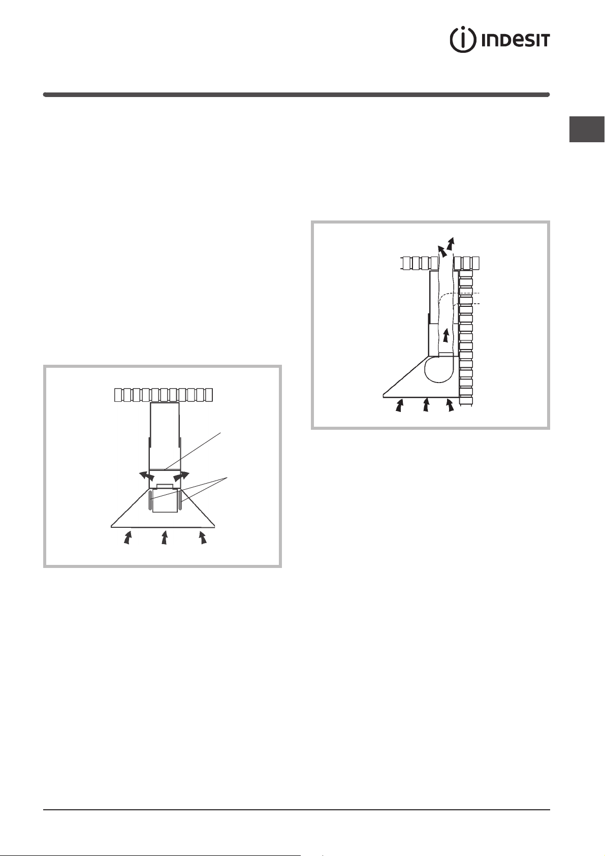
Beschrijving
De kap is beschikbaar als afzuigende of als filterende
versie.
Beslis van te voren welke type installatie u verkiest.
Voor een grotere doeltreffendheid, is het raadzaam de
afzuigende versie te installeren (indien mogelijk).
Filterende versie
De kap zuigt de lucht in de keuken af die verzadigd is
met damp/rook en geuren, en zuivert deze lucht via
die vetfilter en het koolstoffilter, om deze vervolgens
weer gezuiverd in de ruimte te voeren.
Voor deze versie is een luchtafbuigplaat (N) en 2
koolstoffilters (L) nodig.
Om een constante doeltreffende werking te
garanderen, moet de koolstoffilters regelmatig
vervangen worden.
Als de kap niet van een koolstoffilter is voorzien,
moet de klant dit filter aan de verkoper vragen.
Afzuigende versie
NL
De kap zuigt de lucht in de keuken af die verzadigd is
met damp/rook en geuren, voert deze lucht via
die vetfilter, en voert de lucht vervolgens naar buiten
af via een afvoerkanaal.
Bij deze versie is het gebruik van een koolstoffilter
niet nodig.
N
L
53

Werking
NL
Bedieningen
E
A - Toets verlichting
Aan/uit verlichting
B - Toets ON/OFF motor
Aan/uit motor.
De motor start op de eerste snelheid
C - Toets tweede snelheid
Aan/uit motor.
Start de motor op de 2
de
snelheid
A
B
C
D - Toets derde snelheid
Aan/uit motor.
Start de motor op de 3
E = Controlelampje werking motor.
D
de
snelheid
54

Onderhoud
! Schakel altijd de spanning over het apparaat uit
alvorens met een schoonmaak- of
onderhoudsbeurt te beginnen.
! Ter vermijding van mogelijk brandgevaar, houdt
men zich aan de voorschriften voor het
schoonmaken van de anti-vetfilters en
de verwijdering van eventuele vet-aanslag op
het apparaat.
Zorgvuldig onderhoud garandeert een goede werking
en een goed rendement gedurende de levensduur
van het apparaat.
Reiniging van de kap
Eventuele vetafzettingen dienen regelmatig, naar
gelang het gebruik (minstens eenmaal per 2
maanden) van het apparaat te worden verwijderd.
Gebruik geen schurende of corrosieve middelen.
Voor reiniging aan de buitenkant van gelakte
apparaten dient een doek
te worden gebruikt die vochtig gemaakt is in lauw
water en een neutraal reinigingsmiddel; voor reiniging
aan de buitenkant van apparaten van staal, koper
of messing wordt het gebruik van specifieke
producten aangeraden, volgens de instructies op het
product zelf; voor de reiniging van de binnenkant van
het apparaat moet een doek (of kwast) worden
gebruikt
die is ondergedompeld in gedenatureerde
ethylalcohol.
Reiniging van de vetfilters
Druk, om de vetfilters te verwijderen, de
vergrendeling ter hoogte van de handgreep naar
binnen en trek het filter omlaag.
filters afbleken, zal dit in geen enkel geval hun goede
werking in gevaar brengen.
Reinig de vetfilters gemiddeld elke 2 maanden,
afhankelijk van de gebruiksfrequentie.
Vervanging van de koolstoffilters
Als het apparaat gebruikt wordt in de filterversie,
moet de koolstoffilters (L) vervangen worden.
De koolfilter door een kloksgewijze draaibeweging
verwijderen.
L
Vervang de koolstoffilters gemiddeld elke 6
maanden, in verhouding tot het gebruik.
Vervanging van de lampen
Bij deze ingreep moet men met bijzondere
VOORZICHT te werk gaan. Bovendien moet
het aparaat van de spanning gescheiden worden.
Nadat de vetfilters zijn verwijderd, de deksel binnen
de kap met de hand verwijderen. Het mobiele
gedeelte van de 2 stoppen met lichte druk uit het
raam drukken.
De gloeilamp eruit draaien en door een lamp van
hetzelfde type vervangen.
De deksel door lichte druk weer op zijn gelone
positive terug brengen.
NL
De filters met een neutraal reinigingsmiddel
afwassen, met de hand of in de vaatwasmachine. In
het geval dat men de vaatwasmachine gebruikt en de
55

Voorzorgsmaatregelen en
NL
raadgevingen
Algemene veiligheid
! De afstand tussen het draagvlak van de pannen
op de kookplaat en de onderkant van de wasemkap
moet minstens 65 cm zijn. Als de instructies voor
de installatie van de kookplaat een grotere afstand
specificeren, moet deze in aanmerking genomen
worden.
! Dit apparaat vertoont opbouwende technische
omzichtigheden zodat het gerekend kan
worden in de isolatie-klas ll en dus daarom
niet geaard gehoeft te worden.
! Vermijd het gebruik van materiaal dat
steekvlammen kan veroorzaken in de nabijheid
van het apparaat.
! Bij het frituren moet men vooral letten op
het brandgevaar dat bestaat bij het gebruik van olie
en vetten. Met name reeds gebruikte olie is
gevaarlijk vanwege hun ontvlambaarheid.
! Gebruik geen open elektrische gril.
! Het is aanbevolen geen zware gewichten op de kap
te plaatsen.
04307843/1S
van de warmtebron worden aangezogen.
De ruimte moet daarom voorzien zijn van
een rechtstreekse luchttoevoer, die voor
een konstante verse luchtaanvoer zorgt.
Sloop
De Europese Richtlijn 2002/96/EC over Vernietiging
van Electrische en Electronische Apparatuur (WEEE),
vereist dat oude huishoudelijke electrische apparaten
niet mogen vernietigd via de normale ongesorteerde
afvalstroom. Oude apparaten moeten apart worden
ingezameld om zo het hergebruik van de gebruikte
materialen te optimaliseren en de negatieve invloed op
de gezondheid en het milieu te reduceren. Het
symbool op het product van de “afvalcontainer met
een kruis erdoor” herinnert u aan uw verplichting, dat
wanneer u het apparaat vernietigt, het apparaat apart
moet worden ingezameld. Consumenten moeten
contact opnemen met de locale autoriteiten voor
informatie over de juiste wijze van vernietiging van hun
oude apparaat.
Afvoer van de lucht
Als uw apparaat als afzuigende versie geïnstalleerd
moet worden, zorg er dan voor dat het luchtafvoergaten kanaal gerealiseerd worden.
Om optimale prestaties te verkrijgen,
in de afzuig-versie, wordt een buis voor de lucht-afvoer
gebruikt met de volgende kenmerken: zo kort mogelijk
van lengte, zo min mogelijk bochten (de maximale
hoek van de bocht: 90°), materiaal volgens
de toegestaande voorschriften (afhankelijk van de
staat). Vervolgens wordt aanbevolen grote verschillen
in doorsnede van verschillende buis delen te vermijden
(aanbevolen doorsnede: 150 mm).
! De luchtafvoer van dit apparaat niet aansluiten
op een buis (pijp) die reeds gebruikt wordt voor
de luchtafvoer van niet elektrische apparatuur
(centrale verwarmingsinstallaties, radiatoren,
geiser, enz.).
! Voor de lozing van de af te voeren lucht
de voorschriften van de bevoegde autoriteit in acht
nemen. Verder moet de af te voeren lucht niet via
een holte in de muur verwijderd worden, tenminste
wanneer deze holte niet voor dit doel bestemd is.
! Voorzie de ruimte van een goede ventilatie indien
de kap gelijktijdig wordt gebruikt met andere,
niet elektrische apparaten (gas-, olie, kolenkachels,
enz.). De afzuigkap kan nl. een onderdruk
in de ruimte creëren. De onderdruk in de ruimte
mag niet groter worden dan 0,04 mbar.,
om te voorkomen dat de afvoergassen
56
 Loading...