

Page 1
Montageanleitung
Mounting Instructions
Instructions de montage
Istruzioni di montaggio
Instrucciones de montaje
TT 140
10/2009
Page 2
Inhalt . Contents . Sommaire . Indice . Indice
Warnhinweise
Warnings
Recommandations
Avvertenze
Advertencias
Technische Kennwerte
Specifications
Caractéristiques techniques
Dati tecnici
Datos técnicos
Lieferumfang
Items Supplied
Contenu de la fourniture
Standard di fornitura
Elementos suministrados
4
5
6
7
Abmessungen
Dimensions
Dimensions
Dimensioni
Dimensiones
2
8
9
Page 3
Hinweise zur Montage / Montage
Mounting Procedure / Mounting
Procédure de montage / Montage
Avvertenze per il montaggio / Montaggio
Indicaciones para el montaje / Montaje
Verbindungsstift / Antastelement wechseln
Exchanging the Connection Pin / Probe Contact
Changer la tige de liaison / lélément de palpage
Sostituire spina di collegament / elemento di tastatura
Cambiar el vástago de unión / elemento de palpación
Elektrische Kennwerte
Electrical data
Valeurs électriques
Dati elettrici
Datos eléctricos
Elektrischer Anschluß
Electrical connection
Raccordement électrique
Collegamento elettrico
Conexión eléctrica
10
12
14
11
13
15
3
Page 4
Warnhinweise . Warnings . Recommandations . Avvertenze . Advertencias
Achtung: Die Montage und Inbetriebnahme ist von einer Fachkraft für Elektrik und Feinmechanik
unter Beachtung der örtlichen Sicherheitsvorschriften vorzunehmen.
Die Steckverbindung darf nur spannungsfrei verbunden oder gelöst werden.
Note: Mounting and commissioning is to be conducted by a specialist in electrical equipment
and precision mechanics under compliance with local safety regulations.
Do not engage or disengage any connections while under power.
Attention: Le montage et la mise en service doivent être réalisés par une personne qualifiée en
électricité et mécanique de précision dans le respect des règles de sécurité locales.
Le connecteur ne doit être branché ou débranché que hors tension.
Attenzione: il montaggio e la messa in funzione devono essere eseguiti da tecnici specialisti
elettricisti e in meccanica di precisione nel rispetto delle norme di sicurezza locali.
Il connettore non può essere collegato o scollegato sotto tensione.
Atención: El montaje y la puesta en marcha deben ser realizados por un especialista en
electricidad y mecánica de precisión, observando las prescripciones locales de seguridad.
Conectar o desconectar el conector sólo en ausencia de tensión.
4
Page 5
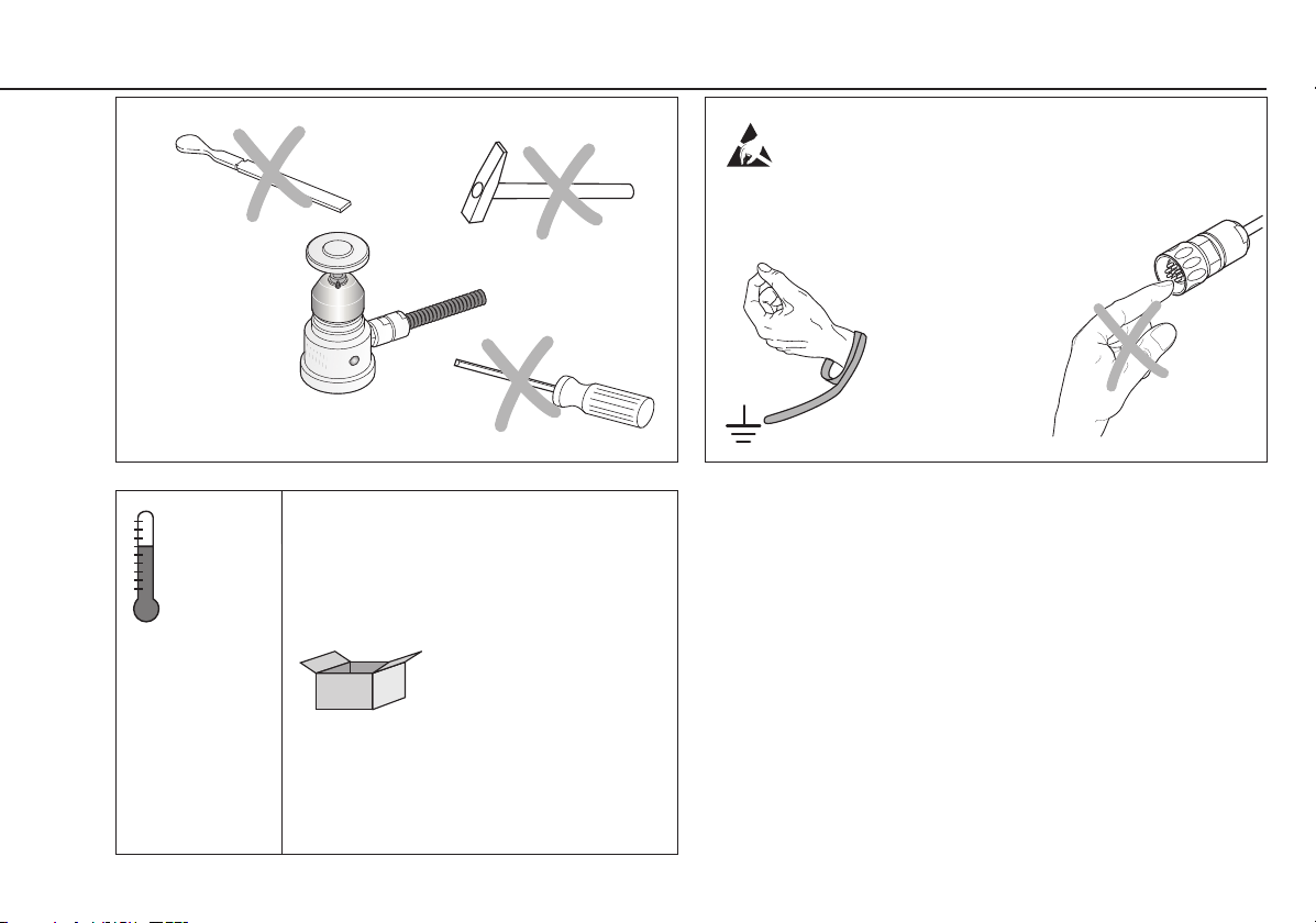
(°C
(°F)
(20 ... 70 °C
( 4 ... 158 °F)
DIN EN 61340 5 1
DIN EN 61340
Maße in mm
Dimensions in mm
Cotes en mm
Dimensioni in mm
Dimensiones en mm
5
2
5
Page 6

Technische Kennwerte . Specifications . Caractéristiques techniques . Dati tecnici . Datos técnicos
F
~ 1 N
5 max.
F
5 max.
~ 8 N
2 s £ 1mm
(v = 0.4 m/min)
6
IP 67
EN 60 529
Page 7

Lieferumfang . Items Supplied . Contenu de la fourniture . Standard di fornitura . Elementos suministrados
Umfang des Lieferumfanges je nach Variante
Scope of delivery depending on variant
Contenu de la fourniture selon la variante
Standard di fornitura a seconda della variante
Elementos suministrados en función de la variante
zusätzlicher Verbindungsstift (mit Sollbruchstelle ID 559 758-01)
Additional connection pin (rated break point lD 559 758-01)
tige de liaison supplémentaire (avec point de rupture ID 559 758-01)
spine di collegamento aggiuntive ( con punta di rottura nominale ID 559 758-01)
vástago de unión adicional (con fusible mecánico ID 559 758-01)
Optionen . Options . Options . Opzioni . Opciones
Antastelement
Probe contact
Elément de palpage
Elemento di tastatura
Elemento de palpación
¬ 25
ID 574 752-01
¬ 40
ID 527 801-01
Ersatzteilkit Stift
Spare parts kit for connection pin
Kit de rechange tige
Kit di sostituzione spine
Kit de recambio del vástago
ID 559 758-01
Montagesockel
Connection fixture
Socle de montage
Dima di montaggio
Zócalo de montaje
ID 332 400-01
7
Page 8

Abmessungen . Dimensions . Dimensions . Dimensioni . Dimensiones
0
¬ 40
0.1
Tolerancing ISO 8015
ISO 2768 - m H
< 6 mm: ±0.2 mm
Befestigung mit Spannpratzen
Mounting with fixing clamps
Fixation avec griffes de serrage
Fissaggio con graffette
Fijación con garras excéntricas
0.01 A
7.5
97
¬ 34
¬ 20
¬ 29.5
0.03 A
4.2
21
¬ 25
¬ 20
7.5
97
4.2
70.9
37
A
1x45°
13
18
¬ 43
0
¬ 48
0.2
¬ 28
¬ 20
71
6.7
M12
¬ 13.5
8
Page 9

Tolerancing ISO 8015
ISO 2768 - m H
< 6 mm: ±0.2 mm
Befestigung auf Montagesockel (Zubehör)
Mounting on connection fixture (accessory)
Fixation avec socle de montage (accessoire)
Fissaggio della dima di montaggio (accessorio)
Fijación sobre zócalo de montaje (accesorio)
19±0.1
1
29.4
M3
Ø 28
Ø 29
38
13
¬ 13.5
¬ 20
¬ 30
¬ 65
30.7
1
8
3
Ø 55
5
5 max.
Ø 47.2+0.3
7 max.
80
9
Page 10

Hinweise
zur Montage
.
Mounting
Procedure
.
Procédure
de montage
.
Avvertenze
per il montaggio
Achtung: Krafteinwirkung kann Verbindungsstift zerstören
Caution: Too much force can destroy the connection pin
Attention: La force exercée peut détruire la tige de liaison
Attenzione: una forza eccessiva potrebbero rompere le spine di collegamento
Atención: La aplicación de fuerza puede dañar el vástago de unión
.
Indicaciones
para el montaje
10
SW2
Md
= 1 Nm
Page 11

Montage . Mounting . Montage . Montaggio . Montaje
3.
¬ 40
2x
M12 ISO 4762
Md = 75 Nm
¬ 25
2.
1.
M12 ISO 4762
Md = 75 Nm
M4
Md = 2.65 Nm
11
Page 12

Verbindungsstift/ Exchanging the Connection Pin/ Changer la tige de liaison/
Antastelement wechseln . Probe Contact
.
lélément de palpage
.
1.
1x (2x) lösen
Loosen 1 (2) screw(s)
Dévisser 1x (x2)
1x (2x) allentare
Desatornillar 1x (2x)
SW2
3.
Verbindungsstift auswechseln
Exchange the connection pin
Changer la tige de liaison
sostituire la spina di collegamento
Cambiar el vástago de unión
neue Schraube verwenden (Lieferumfang)
Use a new screw (included in items supplied)
Utiliser une nouvelle vis (dans la fourniture)
utilizzare viti nuove (nello standard di fornitura)
utilizar nuevo tornillo (contenido en elementos suministrados)
2.
Antastelement entnehmen
Remove the probe contact
Retirer lélément de palpage
Md
sfilare l'elemento di tastatura
Retirar el elemento de palpación
= 1 Nm
12
Page 13

Sostituire spina di collegament/ Cambiar el vástago de unión/
elemento di tastatura
.
elemento de palpación
4.
Antastelement befestigen
Secure the probe contact
Fixer lélément de palpage
Fissare l'elemento di tastatura
Fijar el elemento de palpación
neue Schraube verwenden (Lieferumfang)
Use a new screw (included in items supplied)
Utiliser une nouvelle vis (dans la fourniture)
utilizzare viti nuove (nello standard di fornitura)
utilizar nuevo tornillo (contenido en elementos suministrados)
Achtung: Krafteinwirkung kann Verbindungsstift zerstören
Caution: Too much force can destroy the connection pin
Attention: La force exercée peut détruire la tige de liaison
Attenzione: una forza eccessiva potrebbero rompere le spine di collegamento
SW2
Atención: La aplicación de fuerza puede dañar el vástago de unión
Md
= 1 Nm
5.
Tastsystem neu Kalibrieren
Recalibrate the touch probe
Réétalonner le palpeur
Ricalibrare il sistema di tastatura
Volver a calibrar el sistema de palpación
13
Page 14

Elektrische Kennwerte . Electrical data . Valeurs électriques . Dati elettrici . Datos eléctricos
U
= 10 ...30 V
P
(max. 100 mA)
EN 50 178
PELV EN 60 204-1
t £
10 µs
HTL
S
S
UH ³ [UP 4 V]
(I
UL £ 2.8 V
(IL £ 20 mA)
£ 20 mA)
H
14
= Schaltsignal
S , S
Trigger signal
Signal de commutation
Segnale di commutazione
Señal de connexión
Page 15

Elektrischer Anschluß . Electrical connection . Raccordement électrique . Collegamento elettrico . Conexión eléctrica
1
1
6
2
7
5
3
4
6
7
5
2
3
4
ID 310 194-xx
1
U
WH
2
U
N
P
BN
3
S
GN
4
S
YE
* Brücke . Bridge . pont . ponte . puente
Schirm auf Gehäuse
Shield on housing
Blindage sur boîtìer
Schermo sulla carcassa
Blindaje a carcasa
5
/
6
*
/
7
/
/
1
U
N
WHGN
2
U
P
BNGN BN GN
3
S
4
S
5
GY
6
//
PK
7
/
/
50 m max.
NC
> 100 mm
> 100 mm
> 200 mm
Störquellen
M
Noise sources
Sources parasites
Origine del disturbo
Fuentes de interferencias
15
Page 16

DR. JOHANNES HEIDENHAIN GmbH
Dr.-Johannes-Heidenhain-Straße 5
83301 Traunreut, Germany
{ +49 8669 31-0
| +49 8669 5061
E-mail: info@heidenhain.de
Technical support | +49 8669 32-1000
Measuring systems { +49 8669 31-3104
E-mail: service.ms-support@heidenhain.de
TNC support { +49 8669 31-3101
E-mail: service.nc-support@heidenhain.de
NC programming { +49 8669 31-3103
E-mail: service.nc-pgm@heidenhain.de
PLC programming { +49 8669 31-3102
E-mail: service.plc@heidenhain.de
Lathe controls { +49 8669 31-3105
E-mail: service.lathe-support@heidenhain.de
www.heidenhain.de
*I_590087-91*
590 087-91 · Ver00 · 2 · 10/2009 · H · Printed in Germany
 Loading...