

Page 1

User’s Manual
CNC Pilot 4290
NC Software
625 952-xx
V7.1
English (en)
4/2010
Page 2
Page 3
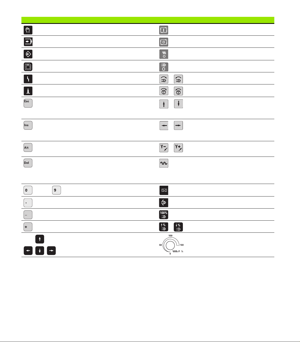
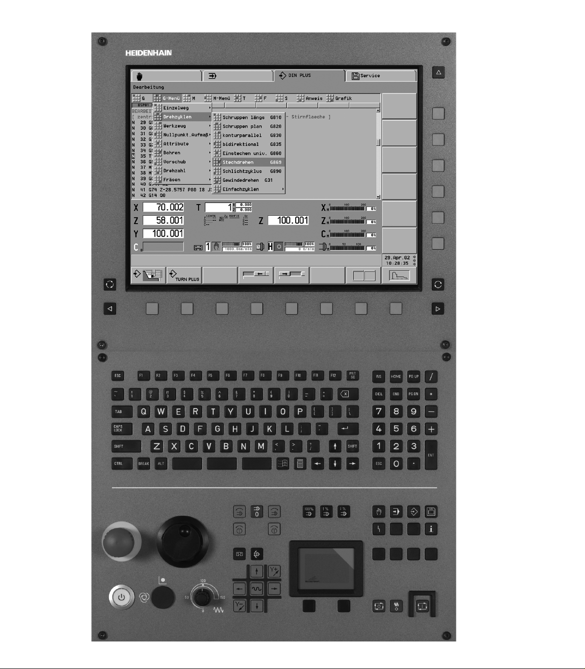
Data input keypad Machine operating panel
Manual control operating mode Cycle start
Automatic operating mode Cycle stop
Programming modes (DIN PLUS, simulation, TURN
PLUS)
Organization modes (parameter, service, transfer) Spindle STOP
Display error status Spindle on - M3/M4 direction
Call the info system Spindle jog - M3/M4 direction (The spindle
ESC
Back by one menu level
Close dialog box, do not save data
INS
Insert list element
Close dialog box, save data
ALT
Edits a list element
DEL
Deletes the list element
Deletes the selected character or the character to the
left of the cursor
. . . Numerals for entering values and
selecting soft keys
Decimal point Spindle change key
Feed rate stop
turns until you press the key.)
Manual direction keys +X/–X
Manual direction keys +Z/–Z
Manual direction keys +Y/–Y
Rapid-traverse key
Slide change key
Minus as algebraic sign Spindle speed at the programmed value
“Continue key” for special functions (e.g. marking) Increase/decrease spindle speed by 5%
Cursor keys Override button for feed-rate override
HEIDENHAIN CNC PILOT 4290 3
Page 4
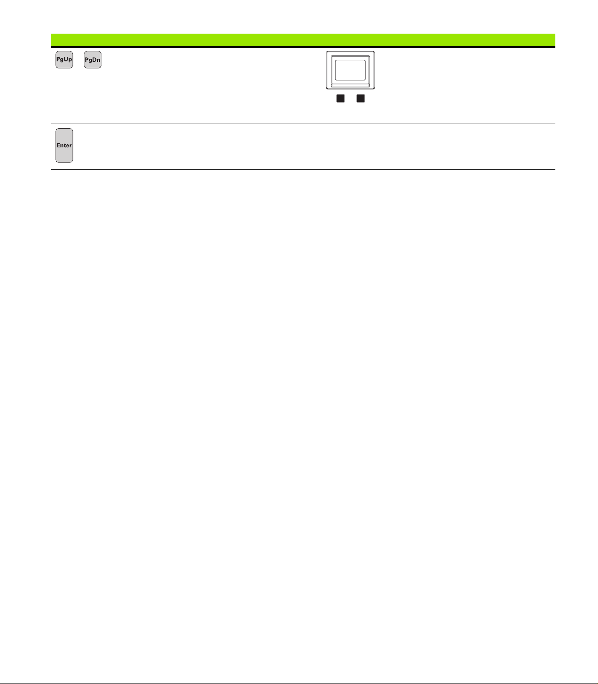
Data input keypad Machine operating panel
Page up, Page down (PgUp/PgDn)
Change to previous/next screen page
Change to previous/next screen dialog box
Switches between input windows
Enter – Confirmation of input
Touchpad with right and left mouse key
4
Page 5

CNC PILOT 4290, Software and Functions
This manual describes functions that are available in the CNC
PILOT 4290 with NC software number 625 (Release 7.1). For
programming the B and Y axes, please refer to the User's Manual
“CNC PILOT 4290 with B and Y Axes”. It is not described in this
manual.
The machine manufacturer adapts the features offered by the control
to the capabilities of the specific lathe by setting machine parameters.
Therefore, some of the functions described in this manual may not be
among the features provided by the CNC PILOT on your machine tool.
CNC PILOT functions that may not be available on your machine
include:
Machining with the C Axis
Machining with the B axis
Machining with the Y-axis
Full-surface machining
Tool monitoring
Graphically supported interactive contour definition
Automatic or graphically supported interactive DIN PLUS program
generation
Please contact your machine manufacturer for detailed information on
the features that are supported by your machine tool.
Many machine manufacturers and HEIDENHAIN offer programming
courses for the CNC PILOT controls. We recommend these courses
as an effective way of improving your programming skill and sharing
information and ideas with other CNC PILOT users.
HEIDENHAIN also offers the PC software DataPilot 4290, which is
designed for use with the CNC PILOT 4290. The DataPilot is suitable
for both shop-floor programming as well as off-location program
creation and testing. It is also ideal for training purposes.
Intended place of operation
The CNC PILOT 4290 complies with the limits for a Class A device in
accordance with the specifications in EN 55022, and is intended for
use primarily in industrially-zoned areas.
HEIDENHAIN CNC PILOT 4290 5
Page 6

Page 7

Contents
Introduction and Fundamentals
1
Basics of Operation
2
Manual Control and Automatic Modes
3
ISO Programming
4
Graphic Simulation
5
TURN PLUS
6
Parameters
7
Operating Resources
8
Service and Diagnosis
9
Tr a n s f e r
10
Tables and Overviews
11
HEIDENHAIN CNC PILOT 4290 7
Page 8

Page 9

1 Introduction and Fundamentals ..... 29
1.1 The CNC PILOT ..... 30
Programming ..... 30
The C axis ..... 31
The Y axis ..... 32
Full-surface machining ..... 33
The B axis ..... 34
1.2 The Modes of Operation ..... 35
1.3 Expansion Stages (Options) ..... 37
1.4 Fundamentals ..... 39
Position encoders and reference marks ..... 39
Axis designations and coordinate system ..... 40
Machine reference points ..... 40
Absolute and incremental workpiece positions ..... 41
Units of measure ..... 42
1.5 Tool Dimensions ..... 43
2 Basics of Operation ..... 45
2.1 User Interface ..... 46
Screen displays ..... 46
Controls and displays ..... 47
Selecting the operating mode ..... 48
Data input, selection of functions ..... 48
2.2 Info and Error System ..... 50
The info system ..... 50
Context-sensitive help ..... 52
Direct error messages ..... 52
Error display ..... 53
Additional information on error messages ..... 54
PLC display ..... 54
2.3 Data Backup ..... 55
2.4 Explanation of Terms ..... 56
3 Manual Control and Automatic Modes ..... 57
3.1 Switch-On, Switch-Off, Reference Run ..... 58
Switch-on ..... 58
Reference run for all axes ..... 58
Reference jog for single axis ..... 59
Monitoring EnDat encoders ..... 59
Switch-off ..... 60
HEIDENHAIN CNC PILOT 4290 9
Page 10

3.2 Manual Control Mode ..... 61
Entering the machine data ..... 62
M commands in Manual Control mode ..... 63
Manual turning operations ..... 64
Handwheel ..... 65
Spindle and manual direction keys ..... 65
Slide/spindle change key ..... 66
3.3 Table for Tools and Chucking Equipment ..... 67
Setting up a tool list ..... 68
Comparing a tool list with an NC program ..... 70
Transferring the tool list from an NC program ..... 71
Simple tools ..... 71
Tool life management ..... 72
Setting up the chucking table ..... 74
3.4 Setup Functions ..... 75
Setting the tool changing point ..... 75
Shifting the workpiece zero point ..... 76
Defining the protection zone ..... 77
Setting up machine dimensions ..... 78
Tool measurement ..... 79
Calculate the tool compensation ..... 80
3.5 Automatic Mode ..... 81
Program selection ..... 82
Finding a start block ..... 84
Modifying the program run ..... 85
Compensation ..... 87
Tool life management ..... 88
Inspection mode ..... 89
Block display, variable output ..... 93
Graphic display ..... 94
Mechatronic tailstock ..... 95
Post-process measuring status ..... 96
3.6 Machine Display ..... 97
Switching the display ..... 97
Display elements ..... 97
3.7 Load Monitoring ..... 100
Machining using load monitoring ..... 101
Reference machining ..... 102
Production using load monitoring ..... 103
Editing limit values ..... 103
Analyzing reference machining ..... 104
Load monitoring parameters ..... 105
10
Page 11

4 DIN Programming ..... 107
4.1 DIN Programming ..... 108
Introduction ..... 108
DIN PLUS screen ..... 109
Linear and rotary axes ..... 110
Units of measurement ..... 111
Elements of a DIN program ..... 111
4.2 Programming Notes ..... 113
Configuring the DIN editor ..... 113
Parallel editing ..... 114
Selecting submenus, positioning the cursor ..... 114
Making, editing and deleting NC blocks ..... 115
Search functions ..... 116
Conversational or free editing ..... 117
Geometry and machining commands ..... 117
Contour programming ..... 118
List of G functions ..... 120
Address parameters ..... 120
Tool programming ..... 121
Subprograms, expert programs ..... 122
NC program conversion ..... 122
Fixed cycles ..... 123
4.3 The DIN PLUS Editor ..... 124
Overview of main menu ..... 124
Overview of geometry menu ..... 125
Overview of machining menu ..... 126
New NC program ..... 127
NC program management ..... 128
Graphics window ..... 129
Workpiece-blank programming ..... 130
Block numbering ..... 130
Programming instructions ..... 131
Block group menu ..... 133
HEIDENHAIN CNC PILOT 4290 11
Page 12

4.4 Program Section Code ..... 135
PROGRAM HEAD section ..... 136
TURRET section ..... 137
CHUCKING EQUIPMENT section ..... 142
CONTOUR section ..... 143
BLANK section ..... 143
FINISHED PART section ..... 143
AUXILIARY CONTOUR section ..... 144
FRONT section ..... 144
REAR SIDE section ..... 144
SURFACE section ..... 144
MACHINING section ..... 144
END code ..... 144
ZUORDNUNG [ASSIGNMENT] instruction $.. ..... 144
SUBPROGRAM section ..... 145
RETURN code ..... 145
CONST code ..... 145
4.5 Definition of Workpiece Blank ..... 146
Chuck piece: bar/tube G20-Geo ..... 146
Casting G21-Geo ..... 146
4.6 Basic Contour Elements ..... 147
Starting point of turning contour G0-Geo ..... 147
Line segment in a contour G1-Geo ..... 147
Circular arc of turning contour G2/G3-Geo ..... 148
Circular arc of turning contour G12/G13-Geo ..... 150
4.7 Contour Form Elements ..... 152
Recess (standard) G22-Geo ..... 152
Recess (general) G23-Geo ..... 153
Thread with undercut G24-Geo ..... 155
Undercut contour G25-Geo ..... 156
Thread (standard) G34-Geo ..... 159
Thread (general) G37-Geo ..... 160
Hole (centric) G49-Geo ..... 162
4.8 Attributes for Contour Description ..... 163
Precision stop ..... 164
Surface roughness G10-Geo ..... 164
Feed rate reduction factor G38-Geo ..... 165
Attributes for superimposed elements G39-Geo ..... 165
Blockwise oversize G52-Geo ..... 166
Feed per revolution G95-Geo ..... 166
Additive compensation G149-Geo ..... 167
4.9 C-Axis Contours—Fundamentals ..... 168
Milling contour position ..... 168
Circular pattern with circular slots ..... 169
12
Page 13

4.10 Front and Rear Face Contours ..... 172
Starting point of front/rear face contour G100-Geo ..... 172
Line segment in front/rear face contour G101-Geo ..... 172
Circular arc in front/rear face contour G102/G103-Geo ..... 173
Bore hole on front/rear face G300-Geo ..... 174
Linear slot on front/rear face G301-Geo ..... 175
Circular slot on front/rear face G302/G303-Geo ..... 175
Full circle on front/rear face G304-Geo ..... 176
Rectangle on front/rear face G305-Geo ..... 176
Eccentric polygon on front/rear face G307-Geo ..... 177
Linear pattern on front/rear face G401-Geo ..... 177
Circular pattern on front/rear face G402-Geo ..... 178
4.11 Lateral Surface Contours ..... 179
Starting point of lateral surface contour G110-Geo ..... 179
Line segment in a lateral surface contour G111-Geo ..... 179
Circular arc in lateral surface contour G112-/G113-Geo ..... 180
Hole on lateral surface G310-Geo ..... 181
Linear slot on lateral surface G311-Geo ..... 182
Circular slot on lateral surface G312/G313-Geo ..... 182
Full circle on lateral surface G314-Geo ..... 183
Rectangle on lateral surface G315-Geo ..... 183
Eccentric polygon on lateral surface G317-Geo ..... 184
Linear pattern on lateral surface G411-Geo ..... 185
Circular pattern on lateral surface G412-Geo ..... 186
4.12 Tool Positioning ..... 187
Rapid traverse G0 ..... 187
Setting the tool change position G14 ..... 187
Rapid traverse to machine coordinates G701 ..... 188
4.13 Simple Linear and Circular Movements ..... 189
Linear path G1 ..... 189
Circular path G2/ G3 ..... 190
Circular path G12/ G13 ..... 191
4.14 Feed Rate and Spindle Speed ..... 192
Rotational speed limiting G26 ..... 192
Acceleration (slope) G48 ..... 192
Interrupted feed G64 ..... 193
Feed per minute for rotary axes G192 ..... 193
Feed per tooth Gx93 ..... 194
Constant feed rate G94 (feed per minute) ..... 194
Feed per revolution Gx95 ..... 194
Constant surface speed Gx96 ..... 195
Speed Gx97 ..... 195
HEIDENHAIN CNC PILOT 4290 13
Page 14

4.15 Tool-Tip and Cutter Radius Compensation ..... 196
G40: Switch off TRC/MCRC ..... 197
G41/G42: Switch on TRC/MCRC ..... 197
4.16 Zero Point Shifts ..... 198
Zero point shift G51 ..... 199
Parameter-dependent zero offset G53, G54, G55 ..... 199
Additive zero point shift G56 ..... 200
Absolute zero point shift G59 ..... 201
Mirror/shift contour G121 ..... 202
4.17 Oversizes ..... 204
Switch off oversize G50 ..... 204
Axis-parallel oversize G57 ..... 204
Contour-parallel oversize (equidistant) G58 ..... 205
4.18 Safety Clearances ..... 206
Safety clearance G47 ..... 206
Safety clearance G147 ..... 206
4.19 Tools, Types of Compensation ..... 207
Tool call – T ..... 207
(Changing the) tool edge compensation G148 ..... 208
Additive compensation G149 ..... 209
Compensation of right-hand tool tip G150
Compensation of left-hand tool tip G151 ..... 210
Adding tool dimensions G710 ..... 211
4.20 Contour-Based Turning Cycles ..... 212
Working with cycles ..... 212
Longitudinal roughing G810 ..... 212
Face roughing G820 ..... 215
Contour-parallel roughing G830 ..... 218
Contour-parallel with neutral tool G835 ..... 220
Recessing G860 ..... 222
Recessing cycle G866 ..... 224
Recess turning cycle G869 ..... 225
Finish contour G890 ..... 228
4.21 Simple Turning Cycles ..... 231
End of cycle G80 ..... 231
Simple longitudinal roughing G81 ..... 231
Simple face roughing G82 ..... 232
Simple contour repeat cycle G83 ..... 234
Undercut cycle G85 ..... 235
Recessing G86 ..... 236
Radius cycle G87 ..... 238
Chamfer cycle G88 ..... 238
14
Page 15

4.22 Thread Cycles ..... 239
Thread switch G933 ..... 239
Thread cycle G31 ..... 240
Simple thread cycle G32 ..... 242
Thread single path G33 ..... 244
4.23 Drilling Cycles ..... 246
Drilling cycle G71 ..... 246
Boring, countersinking G72 ..... 248
Tapping G73 ..... 249
Tapping G36 ..... 250
Deep-hole drilling G74 ..... 251
4.24 C-Axis Commands ..... 253
No. of C axis G119 ..... 253
Reference diameter G120 ..... 253
Zero point shift, C axis G152 ..... 254
Standardize C axis G153 ..... 254
4.25 Front/Rear-Face Machining ..... 255
Rapid traverse on front/rear face G100 ..... 255
Linear segment on front/rear face G101 ..... 256
Circular arc on front/rear face G102/G103 ..... 257
4.26 Lateral Surface Machining ..... 258
Rapid traverse, lateral surface G110 ..... 258
Line segment on lateral surface G111 ..... 259
Circular arc on lateral surface G112/G113 ..... 260
4.27 Milling Cycles ..... 261
Contour milling G840—Fundamentals ..... 261
Pocket milling, roughing G845 – Fundamentals ..... 270
Pocket milling, finishing G846 ..... 276
Thread milling, axial G799 ..... 278
Engraving on front face G801 ..... 279
Engraving on lateral surface G802 ..... 280
Character set for engraving ..... 280
HEIDENHAIN CNC PILOT 4290 15
Page 16

4.28 Assignment, Synchronization, Workpiece Transfer ..... 282
Converting and mirroring G30 ..... 282
Spindle with workpiece G98 ..... 283
Workpiece group G99 ..... 284
One-sided synchronization G62 ..... 284
Synchronization marking G162 ..... 285
Synchronous start of slides G63 ..... 285
M97 Synchronous function ..... 286
Spindle synchronization G720 ..... 286
C-angle offset G905 ..... 287
Measuring angular offset during spindle synchronization G906 ..... 288
Traversing to a fixed stop G916 ..... 288
Controlled parting using lag error monitoring G917 ..... 291
Controlled parting using spindle monitoring G991 ..... 292
Values for controlled parting G992 ..... 293
4.29 Contour Follow-Up ..... 294
Saving/loading contour follow-up G702 ..... 294
Contour follow-up G703 ..... 294
K default branch G706 ..... 295
4.30 In-process and Post-process Measuring ..... 296
In-process measuring ..... 296
Post-process measurement G915 ..... 298
4.31 Load Monitoring ..... 300
Fundamentals of load monitoring ..... 300
Specifying the monitoring zone G995 ..... 301
Type of monitoring G996 ..... 301
16
Page 17

4.32 Other G Functions ..... 302
Period of dwell G4 ..... 302
Precision stop G7 ..... 302
Precision stop off G8 ..... 302
Precision stop G9 ..... 302
Move rotary axis G15 ..... 303
Switch off protection zone G60 ..... 303
Chucking equipment in simulation G65 ..... 304
Component position G66 ..... 305
Waiting for time G204 ..... 305
Update nominal values G717 ..... 305
Move lag error G718 ..... 306
Actual values in variables G901 ..... 306
Zero-point shift in variables G902 ..... 306
Lag error in variables G903 ..... 306
Block speed monitoring off G907 ..... 306
Feed rate override 100% G908 ..... 307
Interpreter stop G909 ..... 307
Velocity feedforward G918 ..... 307
Spindle override 100% G919 ..... 307
Deactivate zero-point shifts G920 ..... 308
Deactivate zero-point shifts, tool lengths G921 ..... 308
T no. internal G940 ..... 308
Transferring magazine compensation values G941 ..... 309
Servo lag limit G975 ..... 309
Activating zero-point shifts G980 ..... 309
Activate zero-point shifts, tool lengths G981 ..... 310
Sleeve monitoring G930 ..... 310
Shaft speed with V constant G922 ..... 311
4.33 Data Input and Data Output ..... 312
Output window for # variables WINDOW ..... 312
Input of # variables INPUT ..... 312
Output of # variables PRINT ..... 313
V variable simulation ..... 313
Output window for V variables WINDOWA ..... 313
Input of V variables INPUTA ..... 314
Output of V variables PRINTA ..... 314
4.34 Programming with Variables ..... 315
# variables ..... 316
V variables ..... 318
HEIDENHAIN CNC PILOT 4290 17
Page 18

4.35 Conditional Block Run ..... 322
Program branching IF..THEN..ELSE..ENDIF ..... 322
WHILE..ENDWHILE program repeat ..... 323
SWITCH..CASE—program branching ..... 324
Skip level /.. ..... 326
Slide code $.. ..... 326
4.36 Subprograms ..... 327
Subprogram call: L"xx" V1 ..... 327
Dialog texts in subprogram call ..... 328
Help graphics for subprogram calls ..... 329
4.37 M Commands ..... 330
M commands for program-run control ..... 330
Machine commands ..... 331
4.38 Lathes with Multiple Slides ..... 332
Multi-slide programming ..... 332
Program run ..... 334
Positioning the steady rest ..... 334
Traveling steady rest ..... 336
Two slides work simultaneously ..... 338
Two slides work in succession ..... 340
Machining with four-axis cycle ..... 342
4.39 Full-surface machining ..... 344
Fundamentals of full-surface machining ..... 344
Programming of full-surface machining ..... 345
Full-surface machining with opposing spindle ..... 346
Full-surface machining with single spindle ..... 349
4.40 DIN PLUS Program Example ..... 351
Example of a subprogram with contour repetitions ..... 351
4.41 DIN PLUS Templates ..... 354
Starting templates ..... 354
Structure templates ..... 354
Design of structure templates ..... 355
Transfer parameters for structure templates ..... 355
Editing structure templates ..... 356
Help graphics for structure templates ..... 356
Template menu ..... 356
Template example ..... 357
4.42 Connection between Geometry and Machining Commands ..... 359
Turning ..... 359
C-axis machining – front/rear face ..... 360
C-axis machining – lateral surface ..... 360
18
Page 19

5 Graphic Simulation ..... 361
5.1 Simulation Mode of Operation ..... 362
Screen layout, soft keys ..... 363
Graphic elements ..... 364
Displays ..... 364
Zero point shifts ..... 366
Path display ..... 367
Simulation window ..... 368
Setting the simulation window ..... 369
Configuring the simulation ..... 370
Adjusting the section (zoom function) ..... 371
Errors and warnings ..... 372
How to activate the simulation function ..... 372
Simulation mode ..... 373
5.2 Contour Simulation ..... 374
Functions of the contour simulation ..... 374
Contour dimensioning ..... 375
5.3 Machining Simulation ..... 376
Checking the workpiece machining ..... 376
Protection zone and limit switch monitoring (machining simulation) ..... 377
Dynamic limit switch monitoring ..... 377
Contour checking ..... 378
Saving the generated contour ..... 378
Displaying the tool tip reference point ..... 379
5.4 Motion Simulation ..... 380
Real-time simulation ..... 380
Protection zone and limit switch monitoring (motion simulation) ..... 381
Contour checking ..... 381
5.5 3-D View ..... 382
Influencing the 3-D view ..... 382
5.6 Debugging Functions ..... 383
Simulation with starting block ..... 383
Displaying variables ..... 384
Editing variables ..... 385
5.7 Checking Multi-channel Programs ..... 386
5.8 Time Calculation, Synchronous Point Analysis ..... 387
Time Calculation ..... 387
Synchronous point analysis ..... 388
HEIDENHAIN CNC PILOT 4290 19
Page 20

6 TURN PLUS ..... 389
6.1 TURN PLUS Mode of Operation ..... 390
TURN PLUS concept ..... 390
TURN PLUS files ..... 391
TURN PLUS program management ..... 391
Operating notes ..... 392
6.2 Program Head ..... 393
Generating programs for automatic lathes ..... 394
6.3 Workpiece Description ..... 396
Entering the workpiece blank contour ..... 396
Entering the finished part contour ..... 397
Superimposing form elements ..... 398
Integrating overlay elements ..... 399
Entering contours machined with the C axis ..... 400
6.4 Contours of Workpiece Blanks ..... 402
Bar ..... 402
Tube ..... 402
Cast blank (or forged blank) ..... 403
6.5 Contours of Finished Parts ..... 404
Notes on defining contours ..... 404
Starting point of contour ..... 404
Linear elements ..... 405
Circular element ..... 406
6.6 Form Elements ..... 408
Chamfer ..... 408
Rounding ..... 408
Undercut type E ..... 409
Undercut type F ..... 409
Undercut type G ..... 409
Undercut type H ..... 410
Undercut type K ..... 410
Undercut type U ..... 410
Recess general ..... 411
Recess type D (sealing ring) ..... 412
Relief turn (type FD) ..... 413
Recess type S (guarding ring) ..... 413
Thread ..... 414
(Centric) Hole ..... 415
6.7 Overlay Elements ..... 418
Circular arc ..... 418
Wedge/rounded wedge ..... 418
Pontoon ..... 419
Linear superimposition (“linear overlay”) ..... 419
Circular superimposition (“circular overlay”) ..... 420
20
Page 21

6.8 C-Axis Contours ..... 421
Position of a front or rear face contour ..... 421
Position of a lateral surface contour ..... 421
Milling depth ..... 421
Entering the C-axis contour dimensions ..... 422
Front or rear face: Starting point ..... 422
Front or rear face: Linear element ..... 423
Front or rear face: Circular element ..... 424
Front or rear face: Single hole ..... 426
Front or rear face: Circle (full circle) ..... 428
Front or rear face: Rectangle ..... 429
Front or rear face: Polygon ..... 430
Front or rear face: Linear slot ..... 431
Front or rear face: Circular slot ..... 432
Front or rear face: Linear hole or figure pattern ..... 433
Front or rear face: Circular hole or figure pattern ..... 434
Lateral surface: Starting point ..... 435
Lateral surface: Linear element ..... 436
Lateral surface: Circular element ..... 437
Lateral surface: Single hole ..... 438
Lateral surface: Circle (full circle) ..... 440
Lateral surface: Rectangle ..... 441
Lateral surface: Polygon ..... 442
Lateral surface: Linear slot ..... 443
Lateral surface: Circular slot ..... 444
Lateral surface: Linear hole or figure pattern ..... 445
Lateral surface: Circular hole or figure pattern ..... 446
6.9 Help Functions ..... 447
Unresolved contour elements ..... 447
Selections ..... 448
Zero point shift ..... 452
Copying a contour section in linear series ..... 452
Copying a contour section in circular series ..... 453
Copying a contour section by mirroring ..... 453
Calculator ..... 454
Digitizing ..... 455
Checking contour elements (inspector) ..... 456
Error messages ..... 457
6.10 Importing of DXF Contours ..... 458
Fundamentals for DXF import ..... 458
Configuring the DXF Import ..... 459
DXF import ..... 460
HEIDENHAIN CNC PILOT 4290 21
Page 22

6.11 Manipulating Contours ..... 461
Editing the contours of a blank part ..... 461
Deleting contour elements ..... 462
Editing contour elements or form elements ..... 462
Adding a contour or contour element ..... 463
Closing the contour ..... 464
Resolving a contour ..... 464
Trimming – Linear element ..... 465
Trimming – Length of contour ..... 466
Trimming – Radius of arc ..... 466
Trimming – Diameter of linear element ..... 467
Transformations – Fundamentals ..... 467
Transformations – Shifting ..... 468
Transformations – Rotating ..... 468
Transformations – Mirroring ..... 469
Transformations – Inverting ..... 469
6.12 Assigning Attributes ..... 470
Attributes for workpiece blanks ..... 470
Attributes – Oversize ..... 471
Attributes – Feed rate ..... 472
Attributes – Peak-to-valley ..... 472
Attributes – Additive compensation ..... 473
Machining attributes – Measure ..... 473
Machining attributes – Threading ..... 474
Machining attributes – Drill – Retraction plane ..... 475
Machining attributes – Drilling combinations ..... 475
Machining attributes – Contour milling ..... 476
Machining attributes – Area milling ..... 477
Machining attributes – Deburring ..... 478
Machining attributes – Engraving ..... 479
Machining attributes – Precision stop ..... 479
Machining attributes – Separation point ..... 480
Attributes – Exclusion from machining ..... 480
Deleting machining attributes ..... 481
22
Page 23

6.13 Preparing a Machining Process ..... 482
Preparing a machining process – Fundamentals ..... 482
Chucking a workpiece at the spindle ..... 483
Chucking a workpiece at the tailstock ..... 483
Defining the cutting limit ..... 484
Deleting the chucking data ..... 484
Rechuck – Standard machining ..... 485
Rechuck – 1st setup after 2nd setup ..... 486
Parameters for two-jaw, three-jaw or four-jaw chucks ..... 488
Collet chuck parameters ..... 489
Parameters for face drivers (“without chuck”) ..... 489
Parameters for face drivers with jaws (“Three-jaw chuck indirect”) ..... 490
Setting up and managing tool lists ..... 490
HEIDENHAIN CNC PILOT 4290 23
Page 24

6.14 Interactive Working Plan Generation (IWG) ..... 494
Working plan exists ..... 495
Generating a work block ..... 496
Calling a tool ..... 497
Cutting data ..... 497
Cycle specification ..... 498
Overview of roughing operations ..... 499
Roughing longitudinal (G810) ..... 500
Roughing transverse (G820) ..... 501
Roughing contour-parallel (G830) ..... 502
Residual roughing – longitudinal ..... 503
Residual roughing – transverse ..... 504
Residual roughing – contour-parallel ..... 505
Roughing hollowing – neutral tool (G835) ..... 506
Overview of recessing operations ..... 507
Contour recessing radial/axial (G860) ..... 508
Recessing radial/axial (G866) ..... 509
Recess turning radial/axial (G869) ..... 510
Parting ..... 512
Parting and workpiece transfer ..... 513
Overview of drilling operations ..... 516
Centric predrilling (G74) ..... 517
Centering, countersinking (G72) ..... 518
Drilling, reaming, deep-hole drilling ..... 519
Tapping ..... 520
Finishing ..... 521
Finishing – Clearance turning ..... 524
Finishing – undercut ..... 524
Thread machining (G31) ..... 525
Overview of milling operations ..... 526
Contour milling – Roughing/Finishing (G840) ..... 527
Deburring (G840) ..... 529
Engraving (G840) ..... 530
Pocket milling – Roughing/Finishing (G845/G846) ..... 531
Special machining (SM) ..... 532
6.15 Automatic Working Plan Generation (AWG) ..... 534
Generating a working plan ..... 534
Machining sequence – Fundamentals ..... 535
Editing and managing machining sequences ..... 536
Overview of machining sequences ..... 538
6.16 Control Graphics ..... 547
Adjusting the section (zoom function) ..... 547
Setting the control graphics ..... 548
24
Page 25

6.17 Configuring TURN PLUS ..... 549
General settings ..... 549
Configuring windows (views) ..... 550
Configuring the control graphics ..... 550
Setting the coordinate system ..... 551
6.18 Machining Information ..... 552
Tool selection, turret assignment ..... 552
Contour recessing, recess turning ..... 553
Drilling ..... 553
Cutting data, coolant ..... 553
Hollowing ..... 554
Inside contours ..... 555
Drilling ..... 556
Shaft machining ..... 557
Multi-slide machines ..... 559
Full-surface machining ..... 560
6.19 Example ..... 562
Creating a program ..... 562
Defining the workpiece blank ..... 563
Defining the basic contour ..... 563
Defining form elements ..... 564
Preparing the machining process, chucking ..... 565
Generating and saving a working plan ..... 565
7 Parameters ..... 567
7.1 The Parameter Mode of Operation ..... 568
7.2 Editing Parameters ..... 569
Current parameters ..... 569
Parameter lists ..... 569
Editing configuration parameters ..... 570
7.3 Machine Parameters (MP) ..... 571
General machine parameters ..... 571
Machine parameters for slides ..... 572
Machine parameters for spindles ..... 573
Machine parameters for C axes ..... 574
Machine parameters for linear axes ..... 575
7.4 Control Parameters ..... 577
General control parameters ..... 577
Control parameters for simulation ..... 579
Control parameters for machine display ..... 580
7.5 Set-Up Parameters ..... 583
HEIDENHAIN CNC PILOT 4290 25
Page 26

7.6 Machining Parameters ..... 585
1 – Global parameters for finished parts ..... 585
2 – Global technology parameters ..... 586
3 – Centric predrilling ..... 588
4 – Roughing ..... 591
5 – Finishing ..... 594
6 – Recessing and contour recessing ..... 597
7 – Thread cutting ..... 599
8 – Measuring ..... 600
9 – Drilling ..... 600
10 – Milling ..... 602
Load monitoring ..... 603
20 – Direction of rotation for rear-side machining ..... 604
21 – Name of the subroutines ..... 605
22 – Sequence of tool selection ..... 605
23 – Template management ..... 606
24 – Parameter of the rechucking subroutines ..... 606
8 Operating Resources ..... 607
8.1 Tool Database ..... 608
Tool editor ..... 608
Overview of tool types ..... 612
Tool parameters ..... 614
Tool holder, tool mount ..... 624
8.2 Database for Chucking Equipment ..... 628
Chucking equipment editor ..... 628
Chucking equipment lists ..... 629
Chucking equipment data ..... 630
8.3 Technology Database ..... 641
Editing the technology data ..... 642
Cutting-value tables ..... 643
26
Page 27

9 Service and Diagnosis ..... 645
9.1 The Service Mode of Operation ..... 646
9.2 Service Functions ..... 647
Access authorization ..... 647
System service ..... 648
Fixed-word lists ..... 649
9.3 Maintenance System ..... 650
Maintenance dates and intervals ..... 651
Displaying maintenance actions ..... 652
9.4 Diagnosis ..... 655
Information and display ..... 655
Log files and network settings ..... 656
Software update ..... 657
10 Transfer ..... 659
10.1 The Transfer Mode of Operation ..... 660
Overview of data transfer methods ..... 661
Configuring Windows networks ..... 663
Configuring the serial interface or “printer” ..... 666
10.2 Data Transfer ..... 668
Enabling, file types ..... 668
Basics of operation ..... 669
Transmitting and receiving files ..... 671
10.3 Parameters and Operating Resources ..... 674
Transmitting parameters/operating resources ..... 675
Loading parameters/operating resources ..... 676
Backing up and restoring data ..... 677
Viewing parameter, operating-resource or backup files ..... 679
10.4 File Organization ..... 680
Fundamentals for file organization ..... 680
Managing files ..... 681
HEIDENHAIN CNC PILOT 4290 27
Page 28

11 Tables and Overviews ..... 683
11.1 Undercut and Thread Parameters ..... 684
Undercut DIN 76, Parameters ..... 684
Undercut DIN 509 E, Parameters ..... 686
Undercut DIN 509 F, Parameters ..... 686
Thread Parameters ..... 687
Thread pitch ..... 688
11.2 Pin Layouts and Connecting Cables for the Data Interfaces ..... 694
RS-232-C/V.24 interface for HEIDENHAIN devices ..... 694
Non-HEIDENHAIN devices ..... 695
RS-422/V.11 interface ..... 696
Ethernet interface RJ45 socket ..... 696
11.3 Technical Information ..... 697
Specifications ..... 697
Accessories ..... 698
User functions ..... 698
28
Page 29
Introduction and Fundamentals
HEIDENHAIN CNC PILOT 4290 29
Page 30
1.1 The CNC PILOT
The CNC PILOT is a contouring control designed for complex lathes
and turning centers. In addition to turning operations, the control can
also perform milling, drilling and boring operations. The C, Y and B
axes enable you to drill and mill on the front and rear faces, the lateral
surface and oblique planes. And as always, the CNC PILOT supports
full-surface machining with dual-spindles.
The CNC PILOT controls up to six slides, four spindles, two C axes,
one B axis and a pocket-oriented tool magazine. The control can
machine up to four workpieces simultaneously.
1.1 The CNC PILOT
Programming
Depending on the type and complexity of the parts to be machined
and your organization, you can choose the type of programming best
suited to your tasks.
In TURN PLUS you describe the contour of the blank and finished part
using interactive graphics. Then you call the automatic working plan
generation (AWG), and the NC program will be generated fully
automatically on a keystroke. An alternative is the interactive working
plan generation (IWG). When using the IWG, you determine the
sequence of machining and other technical details.
Every working step is shown in the control graphics and can be
corrected immediately. The result of program creation with TURN
PLUS is a structured DIN PLUS program.
TURN PLUS minimizes the number of entries required, but it requires
that the the tool data and cutting data has already been entered.
If TURN PLUS fails to create the optimal NC program for
technologically sophisticated machining operations, or if you
primarily want to reduce the machining time, write the NC program
with DIN PLUS.
In DIN PLUS you first describe the contour of the workpiece blank and
finished part. The “simplified geometry programming” calculates
nondimensioned coordinates if, for example, the drawing is not
dimensioned for conventional NC. Then you write the NC program
using powerful fixed cycles.
Both TURN PLUS and DIN PLUS support a C or Y axis and full-surface
machining. DIN PLUS cycles are available for working with the B axis.
As an alternative, you can machine your workpiece in DIN PLUS with
linear and circular movements and simple turning cycles, as you are
accustomed to in conventional DIN programming.
30
Page 31

The graphic simulation feature enables you to subject your NC
programs to a realistic test. The CNC PILOT displays the machining of
up to four workpieces in the working space. The simulation shows
workpiece blanks and finished parts, chucking equipment and tools to
scale. When working with the tilted B axis, the working plane is also
shown tilted. This enables you to see, without distortion, the holes and
milling contours to be machined.
You can program your NC programs and test them—even during
machining operations—directly on the machine.
Regardless of whether you are machining a simple or complex part,
producing a single part or a series of parts, or a whole batch on a
turning center, the CNC PILOT always gives you optimum support.
The C axis
With a C axis you can drill and mill a workpiece on its front, back and
lateral surfaces.
When the C axis is used, one axis interpolates linearly or circularly with
the spindle in the given working plane, while the third axis interpolates
linearly.
The CNC PILOT supports part program creation with the C axis in:
DIN PLUS
TURN PLUS contour definition
TURN PLUS working plan generation
1.1 The CNC PILOT
HEIDENHAIN CNC PILOT 4290 31
Page 32

The Y axis
With a Y axis you can drill and mill a workpiece on its front, back and
lateral surfaces.
During use of the Y-axis, two axes interpolate linearly or circularly in
the given working plane, while the third axis interpolates linearly. This
enables you to machine slots or pockets, for example, with plane
floors and perpendicular edges. By defining the spindle angle, you can
determine the position of the milling contour on the workpiece.
The CNC PILOT supports part program creation with the Y axis in:
DIN PLUS
TURN PLUS contour definition
1.1 The CNC PILOT
TURN PLUS working plan generation
32
Page 33

Full-surface machining
Functions like angle-synchronous part transfer with rotating spindle,
traversing to a stop, controlled parting, and coordinate transformation
ensures efficient machining as well as simple programming of fullsurface machining.
The functions for full-surface machining are available in:
DIN PLUS
TURN PLUS contour definition
TURN PLUS working plan generation
The CNC PILOT supports full-surface machining for all common
machine designs.
Examples: Lathes with
Rotating gripper
Movable opposing spindle
Several spindles, slides and tool carriers
1.1 The CNC PILOT
HEIDENHAIN CNC PILOT 4290 33
Page 34

The B axis
The B axis makes it possible to drill, bore and mill in oblique planes.
To make programming easy, the coordinate system is tilted in such a
way that you can define the drilling patterns and milling contours in the
YZ plane. The actual drilling or milling operation is then performed in
the tilted plane.
During work on the tilted plane, the tool is perpendicular to the plane.
The tilting angle of the B axis and the angle of the tilted plane are
identical.
Another advantage of the B axis is the flexible use of tools during
turning operations. By tilting the B axis and rotating the tool you can
1.1 The CNC PILOT
bring it into positions that enable you to use one and the same tool to
machine in the longitudinal and transverse (or radial and axial)
directions on the main and opposing spindles.
In this way, you need fewer tools and fewer tool changes.
The CNC PILOT supports part program creation with the B axis in
DIN PLUS.
The graphical simulation shows the machining operation in a tilted
working plane in the familiar lathe and front windows, as well as in the
“side view (YZ).”
User's Manual for the B and Y axes
The manual and automatic control functions a well as the
programming and testing of NC programs for the B and Y
axes are described in a separate User's Manual. Please
contact HEIDENHAIN if you require a copy of this User's
Manual.
34
Page 35

1.2 The Modes of Operation
Operating modes
Manual mode: In the Manual Control mode you set up
the machine and move the axes manually.
Automatic mode: NC in Automatic mode, NC programs
are executed from start to end. You control and monitor
the machining of the workpieces.
DIN PLUS programming mode: You write the
structured NC programs in DIN PLUS. First you define
the geometry of the blank and finished part, and then
program the machining of the workpiece.
Simulation programming mode: The Simulation mode
graphically depicts contours, tool movements and cutting
processes. The working space, tools and chucking
equipment are shown true to scale.
During simulation, the CNC PILOT calculates the
machining and idle-machine times for every tool. For
lathes with several slides, the synchronous point
analysis enables you to optimize your NC program.
TURN PLUS programming mode: In TURN PLUS you
describe the workpiece contour interactively in a graphic.
If you then define the material and chucking equipment,
the Automatic Working plan Generation (AWG) will
generate the NC program automatically at a keystroke.
As an alternative, you can create the working plan with
the aid of interactive graphics (IAG).
1.2 The Modes of Operation
Parameter organization mode: The system behavior of
the CNC PILOT is controlled by parameters. In this mode,
you set the parameters to adapt the control to your
situation.
In addition, in this mode you describe the operating
resources (tools and chucking equipment) and the
cutting values.
HEIDENHAIN CNC PILOT 4290 35
Page 36

Operating modes
Service organization mode: In Service you log in for
password-protected functions, select the conversational
language and make system settings. This operating
mode also provides diagnostic functions for
commissioning and checking the system.
Transfer organization mode: In Transfer, you exchange
data with other systems, organize your programs and
back-up your data.
The actual control is not accessible to the machinist. You should know,
however, that your CNC PILOT stores all TURN PLUS and DIN PLUS
programs that you enter on an integrated hard disk. This allows you to
save a vast number of programs.
For data exchange and data backup, you can use the Ethernet
interface and the USB memory medium. Data exchange on the basis
of the serial interface (RS-232) is also possible.
1.2 The Modes of Operation
36
Page 37

1.3 Expansion Stages (Options)
The machine manufacturer configures the CNC PILOT according to
the capabilities of the specific lathe. The following upgrades (options)
are available, which enable you to adapt the control to your specific
requirements:
TURN PLUS – Basis (ID 354 132-01):
Graphically supported interactive contour definition
Graphic program entry for describing the workpiece blank and
finished part
Geometry program for calculating and depicting contour points for
which dimensional data are missing
Simple entry of standardized form elements such as chamfers,
rounding arcs, undercuts, recesses, threads, fits
Simple handling of transformations such as datum shift, rotation,
mirroring, duplication
Graphically supported interactive DIN PLUS program generation
Individual selection of the operating mode
Selection of the tool and specification of cutting data
Direct graphic verification of the metal removing operation
Direct compensation capability
Automatic DIN PLUS program generation
Automatic tool selection
Automatic generation of the working plan
TURN PLUS – C-axis option (ID 354 133-01):
Depiction of programming in the XC plane (front/rear face) and ZC
plane (unrolled lateral surface view)
Hole pattern and figure pattern; any milled contours
Interactive or automatic generation of the working plan, including C-
axis machining
TURN PLUS – option for opposing spindles
(ID 354 134-01):
Rechucking with expert program
Interactive or automatic generation of the working plan, including
rechucking and machining the second setup
TURN PLUS – DXF import (ID 526 461-01):
In TURN PLUS, read in the contours (blank and finished part
contours, milled contours, contour trains) that are available in DXF
format
View and select DXF layers
Load DXF contour into TURN PLUS
1.3 Expansion Stages (Options)
HEIDENHAIN CNC PILOT 4290 37
Page 38

Opposing spindle—full-surface machining of a workpiece
(ID 518 289-01):
Spindle synchronism (G720)
Parting control (G917, G991, G992)
Traversing to a dead stop (G916)
Mirroring and converting (G30)
In-process measurement—measuring on the machine
(ID 354 536-01):
With touch trigger probe
For tool setup
For workpiece measurement
Post-process measurement—measuring on external measuring
stations
(ID 354 537-01):
Connecting the measuring equipment over the RS-232 interface
Evaluating the measurement results in the NC program
Y axis (ID 354 138-01)
Support of Y axis programming in DIN PLUS, TURN PLUS and in
1.3 Expansion Stages (Options)
simulation
Depiction of programming in the XY (front/rear face) and YZ (lateral
surface view) planes
DIN PLUS and TURN PLUS: Drilling, boring and figure patterns; any
milling contours
DIN PLUS: Cycles for drilling, boring and milling
TURN PLUS: Interactive or automatic generation of the working
plan, including Y-axis machining
B axis (ID 589 963-01)
Support of B axis programming in DIN PLUS and in simulation
The coordinate system is transformed to a tilted place in order to
describe hole and figure patterns as well as any desired contours in
the YZ plane
Fixed cycles work in a tilted plane
Options can usually be retrofitted. Your machine manufacturer can
give you more information.
This description covers all options. The operating
sequences described in this manual may therefore deviate
from those on your machine whenever a certain option is
not supported by your system.
38
Page 39

1.4 Fundamentals
Zref
Xref
M
Position encoders and reference marks
The machine axes are equipped with position encoders that register
the positions of the slide or tool. When a machine axis moves, the
corresponding position encoder generates an electrical signal. The
control evaluates this signal and calculates the precise actual position
of the machine axis.
If there is a power interruption, the calculated position will no longer
correspond to the actual position of the machine slide. To recover this
association, incremental position encoders are provided with
reference marks. The scales of the position encoders contain one or
more reference marks that transmit a signal to the control when they
are crossed over. From the signal the CNC PILOT can re-establish the
assignment of displayed positions to machine positions. For linear
encoders with distance-coded reference marks the machine axes
need to move by no more than 20 mm, for angle encoders by no more
than 20°.
With absolute encoders, an absolute position value is transmitted to
the control immediately upon switch-on. In this way the assignment
of the actual position to the machine slide position is re-established
directly after switch-on.
X
MP
X (Z,Y)
1.4 Fundamentals
HEIDENHAIN CNC PILOT 4290 39
Page 40

Axis designations and coordinate system
+Y
+X
+Z
+C
+B
M
Z
Z+
Y+
X
X+
Coordinate system
The meanings of the coordinates X, Y, Z, B, C are specified in DIN
66 217.
The coordinates entered for the principle axes X and Z are referenced
to the workpiece zero point. The angular data for the rotary axes B and
C are given with respect to the zero point of the respective rotary axis.
On lathes, C axis movements are realized by turning the workpiece
and B axis movements by tilting the tool (swivel head).
1.4 Fundamentals
Axis designations
The cross slide is referred to as the X axis and the saddle as the Z
axis.
All X-axis values that are displayed or entered are regarded as
diameters. In TURN PLUS you can define whether the X axis values
are diameters or radii.
Lathes with Y axis: The Y axis is perpendicular to the X axis and Z axis
(Cartesian system).
When programming paths of traverse, remember to:
Program a positive value to depart the workpiece.
Program a negative value to approach the workpiece.
Machine reference points
Machine zero point
The point of intersection of the X and Z axes is called the machine
zero point. On a lathe, the machine zero point is usually the point of
intersection of the spindle axis and the spindle surface. The machine
zero point is designated with the letter “M”.
Workpiece zero point
For machining a workpiece, it is easier to reference all input data to a
zero point located on the workpiece. By programming the zero point
used in the workpiece drawing, you can take the dimensions directly
from the drawing, without further calculation. This point is the
“workpiece zero point.” The workpiece zero point is designated with
the letter “W”.
40
Page 41

Absolute and incremental workpiece positions
If the coordinates of a position are referenced to the workpiece zero
point, they are referred to as absolute coordinates. Each position on
a workpiece is clearly defined by its absolute coordinates.
Incremental coordinates: Incremental coordinates are given with
respect to the last programmed position. They specify the distance
from the last active position and the subsequent position. Each
position on a workpiece is clearly defined by its incremental
coordinates.
Absolute and incremental polar coordinates: Positions located on
the face or lateral surface can either be entered either in Cartesian
coordinates or polar coordinates.
When programming with polar coordinates, a position on the
workpiece is clearly defined by the entries for diameter and angle.
Absolute polar coordinates refer to the pole and the angle reference
axis. Incremental polar coordinates always refer to the last
programmed nominal position of the tool.
1.4 Fundamentals
HEIDENHAIN CNC PILOT 4290 41
Page 42

Units of measure
You can program the CNC PILOT either in the metric or inch system.
The units of measurement listed in the table below apply to all inputs
and displays.
Measure Metric Inches
Coordinates mm inches
Lengths mm inches
Angle degrees degrees
Shaft speed rpm rpm
1.4 Fundamentals
Cutting speed m/min ft/min
Feed per revolution mm/rev inch/rev
Feed per minute mm/min inch/min
Acceleration m/s
2
ft/s
2
42
Page 43

1.5 Tool Dimensions
The CNC PILOT requires information on the specific tools for a variety
of tasks, such as calculating the cutting radius compensation or the
proportioning of cuts.
Tool dimensions:All position values that are programmed and
displayed are referenced to the distance between the tool tip and
workpiece zero point. Since the control only knows the absolute
position of the tool carrier (slide), The CNC PILOT needs the
dimensions XE and ZE to calculate and display the position of the tool
tip, and for Y axis machining, it also needs the dimension in Y.
Tool compensation: The tool tip is subjected to wear during
machining processes. To compensate for this wear, the CNC PILOT
uses compensation values. The system automatically adds the
compensation values to the values for length.
Tool radius compensation (TRC): The tip of a lathe tool has a certain
radius. When machining tapers, chamfers and radii, this results in
inaccuracies which the CNC PILOT compensates with its cutting
radius compensation function.
Programmed paths of traverse are referenced to the theoretical tool
tip S. The TRC function compensates for this error by calculating a
new path of traverse, the equidistant line.
Milling cutter radius compensation (MCRC):In milling operations,
the outside diameter of the milling cutter determines the contour.
When the MCRC function is not active, the system defines the center
of the cutter as the zero point for paths of traverse. The MCRC
function compensates for cutter radius by calculating a new path of
traverse, the equidistant line.
1.5 Tool Dimensions
HEIDENHAIN CNC PILOT 4290 43
Page 44

1.5 Tool Dimensions
44
Page 45

Basics of Operation
HEIDENHAIN CNC PILOT 4290 45
Page 46

2.1 User Interface
Screen displays
1 Operating mode bar: Shows the status of the operating modes.
The active mode is shown with a dark-gray background.
Programming and organization operating modes:
The selected mode of operation is shown at right next to the
2.1 User Interface
2 Menu bar and pull-down menu enable you to select functions.
3 Working window: Size and content depend on the operating
4 Machine display: Shows the current status of the machine (tool
5 Status bar
6 Calendar date and service “traffic light”
7 Soft-key row: Shows the current meaning of the soft keys.
8 Vertical soft-key row: Shows the current meaning of the soft
symbol.
Additional information such as the selected program,
submode, etc. are shown below the operating mode
symbol.
mode.
position, the cycle and spindle situation, active tool, etc.). The
machine display is configurable.
Simulation, TURN PLUS: Displays the current settings or
information on the next operating steps.
Other operating modes: Displays the most recent error
message
Date and time
A colored background signalizes an error or a PLC message.
The “traffic light” indicates the maintenance status of the
machine.
keys. For more information: see the machine manual.
46
Page 47

Controls and displays
Operating elements of the CNC PILOT:
Screen with
Horizontal and vertical soft keys: The meaning is shown above or
next to the soft keys.
Auxiliary key 1: Acts as the Esc key
Auxiliary key 2: Acts as the Insert key
Auxiliary keys 3: PLC keys
Keyboard with
Alphabetic keyboard with integrated numeric keypad
Keys for operating mode selection
Touchpad: For cursor positioning (menu or soft key selection,
selection from lists, selecting edit boxes, etc.)
Machine operating panel with
Operating elements for the manual and automatic operation of the
lathe (cycle keys, manual direction keys, etc.)
Handwheel for exact positioning in manual mode
Override button for feed-rate override
Operating information on the touchpad: Normally you use the
touchpad as an alternative to the cursor keys. In the following, the
keys below the touchpad are referred to as the left and right mouse
keys.
The functions and operation of the touchpad are similar to the mouse
operation of the Windows operating systems.
Single click of the left mouse key or tap on the mouse pad:
Positions the cursor in lists or input windows.
Activates menu points, soft keys or buttons.
Double click of the left mouse key or double tap on the mouse pad:
Activates the selected element in lists (activates the input
window).
Single click of the right mouse key:
Same function as the Esc key. Prerequisite: the ESC key is
permitted in this situation (for example to go back by one menu
level).
Same function as the left mouse key when selecting soft keys or
buttons.
2.1 User Interface
HEIDENHAIN CNC PILOT 4290 47
Page 48

Selecting the operating mode
Keys for operating mode selection
Manual control operating mode
Automatic operating mode
Programming modes
2.1 User Interface
You can usually switch operating mode at any times. In some
situations, you cannot switch operating modes when a dialog box is
open. In this case, close the dialog box before changing operating
modes. After the change, the new mode starts in the function in which
it was last exited.
In the Programming and Organization operating modes, the CNC
PILOT differentiates between the following situations:
No operating mode is selected (no entry next to the operating mode
symbol): Select the desired mode from the menu.
Operating mode selected (indicated next to the operating mode
symbol): The functions of this operating mode are available.
Within the programming or organization modes, you can switch the
modes by soft key or by repeatedly pressing the corresponding
mode key.
Organization modes
Data input, selection of functions
Data are entered and edited in input windows. An input window
consists of several input fields. You position the cursor with the
touchpad or with the PgUp/PgDn keys to the input box.
Once the cursor is located in the box, you can enter your data or
overwrite existing data. With the right/left arrow keys you can place
the cursor on a position within the input box in order to delete
characters or add data. The “up/down” arrow keys or “Enter” confirm
and terminate the entry.
Some dialogs have more input fields than a window can show. In
these cases, more than one input window appears on the screen, one
superimposed on the other. You will recognize this through the
window number in the top line. To toggle between input windows,
use the PgUp/PgDn keys.
48
Page 49

When you press the OK button, the control accepts the data entered
or edited. As an alternative you can press the Ins key to confirm the
data, regardless of the cursor position. If you leave the input window
by pressing the “Cancel” button or the ESC key, entries or changes
will be lost.
If the dialog consists of more than one input window, you already
confirm the data when pressing the PgUp/PgDn key.
Note: Instead of selecting the OK or Cancel button, you
can press the Ins or Esc key.
List operations: DIN PLUS programs, tool lists, parameter lists, etc.
are displayed as lists. You can scroll through a list with the touchpad
or arrow keys to check data, to select the position where you wish to
enter data, or to highlight items for operations like deleting, copying,
editing, etc.
After having selected the desired list position or a list item, press the
ENTER, INS, ALT or DEL key to execute the operation.
Menu selection: The individual menu items are preceded by the 9field symbol with one field marked. This key represents the key on the
numeric keypad. Press the marked button to select the function.
The function selection begins in the horizontal menu row, then goes
to the pull-down menus. In the pull-down menu you again press the
marked key. As an alternative you can select the menu item with the
touchpad or with the Up/Dn arrow keys and then press ENT.
Soft keys: The meaning of the soft keys is dependent on the current
operating situation. The CNC PILOT indicates the function of the soft
keys with symbols or keywords.
Some soft keys work like “toggle switches.” A function is active when
the associated field in the soft-key row is highlighted in color. The
setting remains in effect until the function is switched off.
Screen buttons: Example of screen buttons are the OK and Cancel
buttons for terminating a dialog box or the buttons contained in the
“Extended inputs” window.
Select the button by cursor and press ENT, or select the button using
the touchpad and press the left mouse button.
2.1 User Interface
HEIDENHAIN CNC PILOT 4290 49
Page 50

2.2 Info and Error System
The info system
The info system calls excerpts from the User's Manual to the screen.
The header shows the selected topic.
You'll usually find information on the current operating situation
(context-sensitive help). if no context-sensitive help is available for a
specific situation look for the topics in the following sources:
The table of contents
The subject index
The search functions
Cross references are marked in the text. Click the cross references by
touchpad to jump to that topic.
Calling and exiting the info system:
2.2 Info and Error System
U Call the info system
U Exit the info system
Contents, subject index, search function: When called, the info
system opens the standard window (figure at upper right). Use the
soft key to switch to the Content/Index window in order to find topics
through the table of contents or subject index, or through the search
function (figure at lower right).
Content/Index window:
U Soft key active: Window is displayed.
U Soft key not active: Window is not displayed.
Size of the info window: Use the soft key to switch the window to
maximum size.
Large window or standard window:
U Soft key active: The info is displayed in the large
window.
U Soft key not active: The info is displayed in the
standard window.
50
Page 51

Navigating in the info system:
U You navigate by touchpad as is usual in Windows
programs.
If the topic of information exceeds the window size:
U Navigate with the up/down cursor keys and PgUp/
PgDn keys through the displayed topic. Prerequisite:
The cursor must be located in the topic window and
not in the Content/Index window.
Moving the cursor:
U Press the soft keys. The cursor switches between the
topic window and the Content/Index window.
Next/previous topic:
U Call the next topic from the table of contents.
U Call the previous topic from the table of contents.
Next/previous topic: The info system saves the history.
U Go to the previous topic.
U Go to the next topic.
OEM help: This soft key is only operable if the machine tool builder
has saved information in the online help.
U Call the OEM help.
2.2 Info and Error System
HEIDENHAIN CNC PILOT 4290 51
Page 52

Context-sensitive help
You'll usually find information on the current operating situation
(context-sensitive help). if no context-sensitive help is available for a
specific situation look for the topics in the following sources:
The table of contents
The subject index
The search functions
Direct error messages
The CNC PILOT uses a direct error message whenever immediate
error correction is possible. Confirm the message and correct the
error.
Example: The input value of the parameter is out of range.
Information of the error message:
2.2 Info and Error System
Error description: Explains the error
Error number: For service questions
Time of day: Time when the error occurred (for your information)
Symbols
Warning: The CNC PILOT indicates the problem. The
program run / operation continues.
Error: The program run/operation is stopped. You must
correct the error before you can continue the current job.
52
Page 53

Error display
If during the system start or program run or other operation an error
occurs, it is indicated in the date box, displayed in the status line, and
saved in the error display.
The date and time remain highlighted in red until all of the errors have
been canceled.
Information of the error message:
Error description: Explains the error
Error number: For service questions
Channel number: Slide for which the error occurred.
Time of day: Time when the error occurred (for your information)
Error class (only with errors):
Background: This message serves as information, or merely a
“small” error has occurred.
Cancel: The current operation (cycle run, traverse command, etc.)
was cancelled. You can resume operation once the error has been
cleared.
Emergency stop: All traverse and the execution of the DIN
program was stopped. You can resume operation once the error
has been cleared.
Reset: All traverse and the execution of the DIN program was
stopped. Switch off the control for a moment, then restart.
Contact your machine manufacturer if the error occurs again.
System error, internal error: If a system error or internal error
occurs, write down all information on the displayed message and
inform your machine manufacturer. You cannot correct an internal
error. Switch off the control and restart.
Warnings during the simulation: In the event of problems during
simulation of an NC program, the CNC PILOT displays a warning in the
top line.
Viewing and deleting error messages:
U Activate the error display. The error system shows all
accumulated errors.
U If more than one error is shown, navigate with the
cursor keys within the error display.
U Deletes the error message marked with the cursor.
2.2 Info and Error System
U Deletes all error messages.
U Display further information on the error marked with
the cursor.
U Exit the error display.
HEIDENHAIN CNC PILOT 4290 53
Page 54

Additional information on error messages
When an error message occurs, press the info key, or place the cursor
on the error message in the error display and then press the info key,
to get further information on the respective error.
Meaning of the soft keys:
U Information on the next error message.
U Information on the previous error message.
U Switches to the general info system
U Switches to the general info system
2.2 Info and Error System
PLC display
The PLC window is used for PLC messages and the PLC diagnosis.
Your machine manual provides more detailed information on the PLC
window.
Activating the PLC display:
U Opens the “error display”
U Switches to the PLC window
U Close PLC window
U Return to error display
The PLC window is shown as alternative to the error window.
54
Page 55

2.3 Data Backup
The CNC PILOT stores NC programs, operating-resource data and
parameters on the hard disk. Since the possibility of damage to the
hard disk due to excessive vibration or shock cannot be eliminated,
HEIDENHAIN recommends making regular backup copies of your
programs, operating resource data and parameters on a PC or on USB
memory media.
You can use DataPilot 4290, the WINDOWS “Explorer” or other
suitable programs for backing up your data on a PC.
For data exchange and data backup, you can use the Ethernet
interface and the USB interface. Data exchange on the basis of the
serial interface (RS-232) is also possible.
2.3 Data Backup
HEIDENHAIN CNC PILOT 4290 55
Page 56

2.4 Explanation of Terms
MP: With machine parameters (MP) the control is interfaced to the
machine, settings are made, etc.
Cursor: In lists, or during data input, a list item, an input field or a
character is highlighted. This “highlight” is called a cursor.
Cursor keys: You can move the cursor with the arrow keys, PgUp,
PgDn of the touchpad.
Navigating: Within a list or an input box, you can move the cursor
to any position you would like to check, change, delete or add to. In
other words, you "navigate" through the list.
Active/inactive functions, menu items: Functions or soft keys
that at present cannot be selected are shown in gray.
Dialog box: Dialog boxes are also called input windows.
Editing: Editing is changing, deleting and adding to parameters,
2.4 Explanation of Terms
commands, etc. within programs, tool data or parameters.
Default value: If the parameters of DIN commands or other
parameters are preassigned values, these values are referred to as
“default values.”
Byte: The capacity of a storage disk is indicated in bytes. Since the
CNC PILOT features a hard disk, the individual program lengths (file
sizes) are expressed in bytes.
Extension: File names consist of the actual name and the
extension. The name part and the extension part are separated by a
dot “.”. The extension indicates the type of file. Examples:
„*.NC“DIN programs
„*.NCS“DIN subprograms
„*.MAS“Machine parameters
56
Page 57

Manual Control and Automatic Modes
HEIDENHAIN CNC PILOT 4290 57
Page 58

3.1 Switch-On, Switch-Off,
Reference Run
Switch-on
In the header, the CNC PILOT displays the individual steps of the
system start and then prompts you to select an operating mode.
Whether the reference run is necessary depends on the encoders
installed:
EnDat encoder: Reference run is not necessary.
Distance-coded encoders: The position of the axes is ascertained
after a short reference run.
Standard encoder: The axes move to known, machine-based points.
After completion of the reference run:
This position display is activated.
Automatic mode can be selected.
The software limit switches are active only after you
have traversed the reference marks.
Reference run for all axes
Select Ref > Reference automatic.
3.1 Switch-On, Switch-Off, Reference Run
The “Status of reference run approach” dialog box informs you of the
current status.
Either set the slides that need to find a reference or set “All slides”
(“reference automatic” dialog box)
To start the reference run, press Cycle Start.
“Feed stop” interrupts the reference run. Cycle start
resumes the reference run.
“Cycle stop” interrupts the reference run.
The sequence in which the axis make their reference run
is defined in MPs 203 and 253 ff.
58
Page 59

Reference jog for single axis
Select Ref > Reference jog.
The “Status of reference run approach” dialog box informs you of the
current status.
Set slides and axes (“Reference jog” dialog box)
The reference run is conducted for as long as the
Cycle Start key stays pressed. To interrupt the
reference run, release the key.
“Cycle stop” interrupts the reference run.
Monitoring EnDat encoders
If your machine is equipped with EnDat encoders, the control saves
the axis positions during switch-off. During switch-on, the CNC PILOT
compares for each axis the position during switch-on with the position
saved during switch-off.
If there is a difference, one of the following messages appears:
“Axis was moved after the machine was switched off.” Check the
current position and confirm it if the axis was in fact moved.
“Saved encoder position of the axis is invalid.” This message is
correct if the control has been switched on for the first time, or if the
encoder or other control components involved were exchanged.
“Parameters were changed. Saved encoder position of the axis is
invalid.” This message is correct if configuration parameters were
changed.
The cause for one of the above listed messages can also be a defect
in the encoder or control. Please contact your machine supplier if the
problem recurs.
3.1 Switch-On, Switch-Off, Reference Run
HEIDENHAIN CNC PILOT 4290 59
Page 60

Switch-off
“Shutdown” is available in the programming and organization modes
if no operating mode is selected.
U Press the soft key to switch off the CNC PILOT.
U Confirm the security query with OK. After a few
seconds, the CNC PILOT requests you to switch off
the machine.
Proper switch-off is recorded in the error log file.
3.1 Switch-On, Switch-Off, Reference Run
60
Page 61

3.2 Manual Control Mode
The Manual Control mode offers various functions for setting up the
machine, for measuring tool dimensions and for manually machining
workpieces.
Options of operation:
Manual mode: With the “machine keys” and the handwheel, you
can control the spindle and move the axes to machine the
workpiece.
Setup mode: Here you enter the tools to be used, set the
workpiece datum, the workpiece change point, the protection zone
dimensions etc. In this way you prepare the machine to machine the
workpieces.
Determining the tool dimensions: You can find the tool
dimensions by touching the workpiece with the tool or with a touch
probe. As an alternative you can measure the dimensions with a
gauge and enter them in the tool database.
For manual control you can configure the machine display for up to
six variants (see “Machine Display” on page 97). You adjust by soft
key which variant will be displayed.
In Manual Control mode, the data are entered and
displayed according to control parameter 1 either in
meters or in inches.
Remember: If the machine has not been referenced:
The position display is not valid.
The software limit switches are not active.
3.2 Manual Control Mode
Soft keys for manual and setup functions
Assign a handwheel to an axis
Set the handwheel transmission
Switch the machine display
Turret one position backward
Turret one position forward
Enter the feed per revolution
Spindle speed, entering
Enter the M function
HEIDENHAIN CNC PILOT 4290 61
Page 62

Entering the machine data
Setting the feed rate
In the menu group F you define a feed rate per revolution or per
minute.
Setting the feed per revolution:
U Select F > Feed per revolution
U Enter the feed rate in mm/rev (or inches/rev)
Setting the feed rate per minute:
U Select F > Feed per minute
U Enter the feed rate in mm/min (or inches/min) and press OK.
Setting the spindle speed or spindle position
In the menu group S, you define the spindle speed, a constant cutting
speed, or you position the spindle.
3.2 Manual Control Mode
Setting the spindle speed:
U Select S > Spindle speed S
U Enter the speed in rpm
Setting the constant surface speed:
U Select S > V constant.
U Enter the cutting speed in m/min (or ft/min) and press OK.
You can enter a constant cutting speed only for slides with
an X axis.
Entering the speed limitation
Available as of software version 625 952-05.
Precondition: Log on as “System manager” (or higher).
U To switch to the required spindle, press the spindle change key
U Select S > Spindle point stop
U Enter the speed in rpm
The current speed limitation for the selected spindle is entered as
proposed value. The speed limitation entered is saved in MP 805, ..
(absolute maximum rpm).
Conduct a spindle point stop (spindle positioning):
U To switch to the required spindle, press the spindle change key
U Select S > Spindle point stop
U Enter the angular position (“spindle point stop” dialog box)
U Cycle Start positions the spindle
U “Cycle stop” exits the dialog box
62
Page 63

Insert the nominal tool
U Select T. Enter the turret position, or
U the next turret position, or
U the previous turret position, or
Functions of the tool change:
Move the tool into position
Calculate “new” tool dimensions
Display “new” actual values in the position display
M commands in Manual Control mode
In the menu group M you either type in the M function to be run or you
select the desired function from the menu.
To run an M function:
U Select M > M direct
U Enter the M number (“M function” dialog box)
U Cycle Start runs the M function
U “Cycle stop” exits the dialog box
3.2 Manual Control Mode
To select and run an M function:
U Select “M function”
U Using the menu, select the M function
U Cycle Start runs the M function
U “Cycle stop” exits the dialog box
The content of the M menu depends on the machine.
Yours may differ from the example shown here.
HEIDENHAIN CNC PILOT 4290 63
Page 64

Manual turning operations
The “manual” menu group includes G functions, simple longitudinal
and transverse turning, and manual NC programs written by the
machine tool builder.
Simple longitudinal and transverse turning operations:
U Select Manual > Constant feed
U Select the direction of feed (“Constant feed” dialog box)
U Control the feed rate with the cycle keys
With “constant speed,” a feed rate per revolution must be
defined.
To run a G function:
U Select Manual > G function
3.2 Manual Control Mode
U Enter the G number (“G function” dialog box)
U Enter the function parameters
U Press OK: The G function is executed
The following G functions are permitted:
G30 – Rear-face machining
G710 – Adding tool dimensions
G602..G699 – PLC functions
Manual NC programs
Depending on the configuration of a lathe, the machine manufacturer
can includes NC programs supporting the machinist in manually
operating the lathe (Example: Switching to rear-face machining).
U Select “Manual”
U Select the desired Manual NC program from the menu
U The control loads the NC program and displays it
U Cycle Start activates the NC program
64
Page 65

Handwheel
U Assign the handwheel to a principal axis or C axis
(“Handwheel axes” dialog box
U Define the feed rate or angle of rotation per
handwheel increment (“Handwheel axes” dialog
box).
U The cancel the handwheel assignment, press the
“Handwheel” soft key with opened dialog box.
The handwheel assignment and speed ratio are shown in the machine
display (the axis letter and the decimal place of the handwheel
traverse ratio are marked).
The handwheel assignment is canceled by:
Switching the slides
Switching the operating modes
Pressing a manual direction key
Spindle and manual direction keys
3.2 Manual Control Mode
The machine operating keys are used for machining under manual
control and for special functions such as finding positions or
compensation values (Teach-in, scratching, etc.).
The tool is activated and the spindle speed and feed rate defined first.
You define the following parameters by MP:
MP 805, 855, ...: Spindle speed during jog
MP 204, MP 254, ...rapid traverse velocity
To move the slide diagonally, press the X and Z axis
direction keys simultaneously.
Spindle keys
Switch the spindle on in M3/M4
direction.
The spindle rotate in M3/M4
direction as long as the key is
pressed (spindle jog)
Spindle STOP
Manual direction keys (jog keys)
Move slide in X direction
Move slide in Z direction
Move slide in Y direction.
To move the slide in rapid
traverse, simultaneously press
the rapid traverse key and the
axis direction key
HEIDENHAIN CNC PILOT 4290 65
Page 66

Slide/spindle change key
On lathes with multiple slides the following keys, functions and
displays refer to the selected slide:
Manual direction keys
Setup functions (for example workpiece zero point setting, set tool
change point)
Slide-dependent display elements of the machine display
Display of the “selected slide”: Machine display
The “selected slide” is listed in the “slide display” (see “Machine
Display” on page 97).
To change the slide, press the slide change key
On lathes with multiple spindles the following keys and displays
refer to the selected spindle:
Spindle keys
3.2 Manual Control Mode
Spindle dependent display elements of the machine display
The “selected spindle” is listed in the “spindle display” (see
“Machine Display” on page 97).
To change the spindle, press the spindle change key
Slide/spindle change key
Switch to the next slide
Switch to the next spindle
66
Page 67

3.3 Table for Tools and Chucking
Equipment
The tool list (turret table) indicates the current tool carrier assignment.
To set up a tool list, enter the ID numbers of the tools.
You can use the entries in the TURRET section of the NC program to
set up the tool list. The “Compare list” and “Accept list” functions
refer to the NC program last interpreted in automatic mode.
Danger of collision
Compare the tool list with the tools actually in the tool
magazine and check the tool carrier before executing
the part program.
The tool list and the dimensions of the registered tools
must correspond to the tool actually present, because
the CNC PILOT uses this data for all slide movements,
protective zone monitoring, and other slide movements.
Soft keys for setting up the tool list
Deleting a tool
Take the tool from the clipboard
Deleting a tool
Place the tool in the clipboard
Edit the tool parameters
Entries in the database – by tool type
Entries in the database – by ID
number
HEIDENHAIN CNC PILOT 4290 67
3.3 Table for Tools and Chucking Equipment
Page 68

Setting up a tool list
In “Setup tool list” you can declare the tool list independently from the
data of an NC program.
Entering a tool
Select Setting up > Tool list > Compile list
Select the tool location.
Entering the tool directly:
3.3 Table for Tools and Chucking Equipment
Press ENTER (or the INS key). The CNC PILOT opens the “Setup”
dialog box
Enter the ID number and click OK to close the dialog box.
Select the tool from the database:
List the tools by type mask, or
List the tools by ID number mask
Place the cursor on the nominal tool.
Insert the tool.
68
Page 69

Deleting a tool
Select Setting up > Tool list > Compile list
Select the tool location.
Use the soft key, or
Press the DEL key to delete the tool
Changing the tool location
Select Setting up > Tool list > Compile list
Select the tool location.
Deletes the tool and saves it in the “ID number
clipboard”
Select a new tool location.
Take the tool from the “ID number clipboard” If the
location was occupied, the previous tool is taken into
the clipboard.
HEIDENHAIN CNC PILOT 4290 69
3.3 Table for Tools and Chucking Equipment
Page 70

Comparing a tool list with an NC program
The CNC PILOT compares the current tool list with the entries in the
NC program last translated in automatic mode. The entries in the
TURRET section are considered to be nominal tools.
The CNC PILOT shows the following tools marked:
Actual tool not equal to nominal tool
Actual tool not occupied, nominal tool occupied
Tool locations that are not assigned in the NC program cannot be
selected.
Danger of collision
Tool pockets that are occupied but, according to the NC
program, are not needed, are not marked.
The CNC PILOT accounts for a tool entered, even if it
does not correspond to the nominal assignment.
Comparing a tool list
Select Setting up > Tool list > Compare list
The CNC PILOT shows the current contents of the tool list and marks
deviations from the programmed tool list.
Select marked tool pocket
3.3 Table for Tools and Chucking Equipment
Press the INS key (or ENTER). The CNC PILOT opens
the “nominal-actual comparison” dialog box
Accept the ID number of the “nominal tool” in the
tool list
Look for the tool in the database
Insert the tool.
70
Page 71

Transferring the tool list from an NC program
The CNC PILOT transfers the new tool assignment from the TURRET
section (reference: the NC program last interpreted in Automatic
mode).
Depending on the previous turret assignment, the following might
occur:
Tool not used: The CNC PILOT enters the new tools in the tool list.
Positions that were occupied in the old tool list, but are not used in
the new list, are retained. Delete the tool, if required.
Actual tool location differs from location in tool list: A tool is not
entered when its newly assigned pocket differs from the pocket
specified in the tool list. The CNC PILOT displays a message
indicating this error. Change the tool location.
As long as a tool position differs from the nominal assignment it
remains highlighted.
Danger of collision
Tool locations that are occupied but, according to the
NC program, are not needed, are kept.
The CNC PILOT accounts for a tool entered, even if it
does not correspond to the nominal assignment.
Accepting the tool list
Select Setting up > Tool list > Accept list
Simple tools
The setup functions use tools that are listed in the database. If the NC
program uses “simple tools,” proceed as follows:
U Run an interpretation of the NC program. The CNC PILOT
automatically updates the tool list.
U If the positions in the tool list are occupied by “old” tools, the
confirmation request “Update tool list?” appears. The entries are
updated only after you have confirmed the request.
Tools that are not registered in the database are identified by the code
“_AUTO_xx” (xx: T number), and not by an ID number.
Define the parameters of simple tools in the NC program.
3.3 Table for Tools and Chucking Equipment
HEIDENHAIN CNC PILOT 4290 71
Page 72

Tool life management
The tool life management allows you to define the sequence of
exchange and declare the tool to be ready for use. The tool life/
quantity is defined in the tool database.
Apart from ID numbers and tool type descriptions, the tool list includes
data for tool life management:
Status: Shows the remaining tool life/quantity.
Ready for use: When the tool life has expired/the defined number
of parts has been produced, the tool is “not ready for use” any
longer.
Atw (replacement tool): If a tool is “not ready for use,” a
replacement tool is inserted.
The “Tool life management” dialog box is used for entering and
displaying the tool life data.
You can use the variable programming in your NC program to evaluate
sequential events that you enter in “Event 1” and “Event 2.”
Tool life management parameters:
Repl. tool (replacement tool): T number (turret position) of the
replacement tool
Event 1: Sequential event that is triggered when the life of a tool has
expired/a tool has produced the defined quantity (Event 21..59).
Event 2: Sequential event that is triggered when the tool life/
quantity of parts of the “last tool” has expired/a tool (Event 21..59).
Ready for use: Set the tool to “ready for use” or “not ready for use”
(applies to tool life management only).
3.3 Table for Tools and Chucking Equipment
72
The tool life data are evaluation only if the tool life
management is active.
Page 73

Entering the tool life parameters
Select Setting up > Tool list > Tool life management
The CNC PILOT displays the entered tools
Select the tool location.
Press ENTER. The CNC PILOT opens the “Tool life management”
dialog box.
Enter the replacement tool and the other tool life parameters.
Press the “New cutting edge” button: The CNC PILOT sets the tool
life/quantity to the value programmed in the database and sets the tool
to ready for use.
Updating the tool life data of all tools
Select Setting up > Tool list > Update tool life management
Confirm the confirmation request with OK; the CNC PILOT sets the
tool life/quantity to the value defined in the database and sets all tools
in the tool carrier to ready for use.
The CNC PILOT displays the “Tool list – Tool life management” for
inspection.
Application example: The cutting edges of all tools used have been
replaced. Part production is to be continued, using the tool life
management function.
3.3 Table for Tools and Chucking Equipment
HEIDENHAIN CNC PILOT 4290 73
Page 74

Setting up the chucking table
The chucking table is evaluated by the concurrent graphics.
To switch to the chucking assignment of further spindles, press the
PgUp/PgDn keys.
Parameters for “spindle x” (main spindle, spindle 1, ..)
Chucking ID: Reference to database
Chuck jaws ID: Reference to database
Chuck supplement ID: Reference to database
Clamp form: Define the inside/outside clamp and clamp step used
Clamping diameter: The diameter at which the workpiece is
clamped. (Workpiece diameter when clamped externally; inside
diameter when internal clamping is used)
“Tailstock” parameters
Sleeve center ID: Reference to database
Setting up the chucking table
Select Setting up > Chucking table > Main spindle (or Tailstock)
For chuck, chuck jaws and chuck supplement: Enter the ID number of
the chucking equipment.
List the chucking equipment by type mask
3.3 Table for Tools and Chucking Equipment
List the chucking equipment by ID number mask
Select the chucking equipment from the database
Clamp form: Press the soft key several times to set
the clamp form
Enter the clamping diameter
74
Page 75

3.4 Setup Functions
Setting the tool changing point
With G14, the slide moves to the tool change point. Always program
the tool change point as far from the workpiece as possible to allow
the turret to rotate to any position.
The tool change point is entered and displayed as distance
between machine zero point and tool carrier zero point.
Since these values are not displayed, it is advisable to
move to the tool change point and “teach-in” the position.
The tool change point is a setup parameter.
Setting the tool changing point
For more than one slide: Define the desired slide
Select Setting up > Tool change point
The “tool change point” dialog box indicates the valid position.
Enter the position of the tool change point.
Teach in the tool change position
Move the slide to the “tool change point.”
Take over the tool change point, or
Move the axis to the tool change point (or X or Y axis).
Take over the position of the axis
3.4 Setup Functions
HEIDENHAIN CNC PILOT 4290 75
Page 76
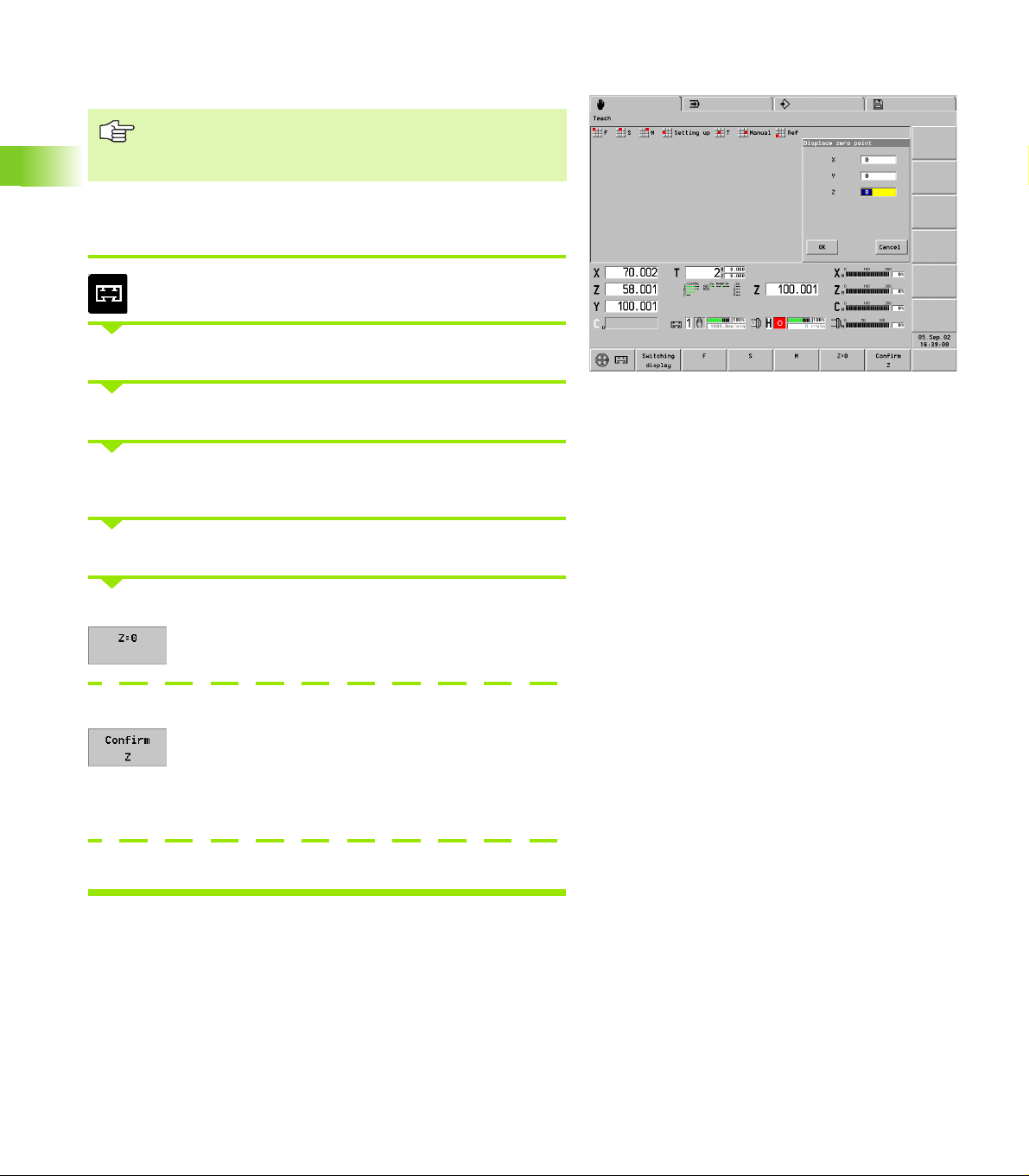
Shifting the workpiece zero point
The shift is referenced to the machine zero point.
You can move the workpiece zero point for all principal
axes.
The workpiece zero point is a setup parameter.
Specify the workpiece datum
For more than one slide: Define the desired slide
3.4 Setup Functions
Move the tool into position
Select Setting up > Shift zero point
The “displace zero point” dialog box displays the new workpiece zero
point.
Touch the tool to the face
Contact position = tool zero point
Accept the tool contact position as workpiece zero
point
Workpiece zero point relative to the contact position
Accept the tool contact position
Enter the measured value (distance of the tool contact position from
the workpiece zero point)
Enter the position of the workpiece zero point
76
Page 77

Defining the protection zone
Protection zone parameters:
Serve for protection zone monitoring—not as software
limit switches
Given with respect to the machine zero point
X values are radius dimensions
99999/-99999 means no monitoring of this protection
zone side
The protection zone parameters are managed in the parameters MP
1116, 1156 and following.
Defining the protection zone
Insert any tool (except T0).
Select Setting up > Selection zones
Teach in the protection zone parameters per axis
Select the input field.
Position the tool to the protection zone limit.
Accept the position as “protection zone -X” (or +X, Y, +Y, -Z, +Z)
3.4 Setup Functions
Teach in positive or negative protection zone parameters
Select any positive or negative input field.
Position the tool to the positive or negative “protection zone.”
Accept all positive or negative axis positions
Enter the protection zone parameters
HEIDENHAIN CNC PILOT 4290 77
Page 78

Setting up machine dimensions
This function takes into account the machine dimensions 1 to 9 and
the “configured axes” per dimension. You can use the machine
dimensions in the NC program.
Machine dimensions are managed in MP 7.
Machine dimensions are given with respect to the
machine zero point.
Define machine dimensions
Select Setting up > Machine dimensions
3.4 Setup Functions
Enter the “machine dimension number”
Teach in a single machine dimension
Select the input field.
Move the axis to the desired “position.”
Confirm the axis position as machine dimension (or Y
or Z position).
Teach in all machine dimensions
Move the slide to the desired “position.”
Accept the axis positions of the slides as machine
dimensions.
Enter machine dimensions
Enter the values (“Set machine dimension x” dialog box)
78
Page 79

Tool measurement
You specify the type of tool measurement in MP 6:
0: Touch-off
1: Measurement with probes
2: Measurement using optical measuring systems
You move according to the measurement method to a certain position
in the working space that is known to the system. Using that
dimension, the CNC PILOT calculates the setting dimensions of the
tool.
The entries in the “Enter measured value” dialog box
are given with respect to the workpiece zero point.
The existing compensation values of the tool are
deleted.
The CNC PILOT enters the calculated tool dimensions
into the database.
Tool measurement
Move the tool into position
Select Setting up > Tool set-up > Tool measuring.
3.4 Setup Functions
The “Tool measuring T...” dialog box indicates the current tool
dimensions.
Finding the tool dimensions by touch-off with the tool
Select the input field X; touch-off the diameter.
Load the diameter
Select the input field Z; touch-off the face.
Accept Z position
Tool measurement with a touch probe
Select the X/Z input field
Move the tool tip in X/Z direction to the touch probe. The CNC PILOT
loads the “dimension X/Z.”
HEIDENHAIN CNC PILOT 4290 79
Page 80

Measure tools with an optical gauge
Select the X/Z input field
Align the tool point in the X/Z direction with the cross hairs.
Load the value (or Z position)
Enter the tool dimensions
Calculate the tool compensation
3.4 Setup Functions
Move the tool into position
Select Setting up > Tool set-up > Tool compensation
Assign the handwheel to the X axis and move the tool by the
compensation value
Assign the handwheel to the Z axis and move the tool by the
compensation value
The CNC PILOT loads the compensation values.
80
Page 81

3.5 Automatic Mode
In Automatic mode, the data are entered and displayed
according to control parameter 1 either in meters or in
inches. The setting in the “program head” of the NC
program governs the execution of the NC part program. It
has no influence on operation or display.
Overview of soft keys in Automatic mode
Switch to “graphic display”
Switch the machine display
Define block display for more
channels
Display basic blocks (individual paths
of traverse)
Suppress/permit variable output
Set single-block mode
Program stop at M01 (selectable
stop)
Run a start-block search
3.5 Automatic Mode
HEIDENHAIN CNC PILOT 4290 81
Page 82
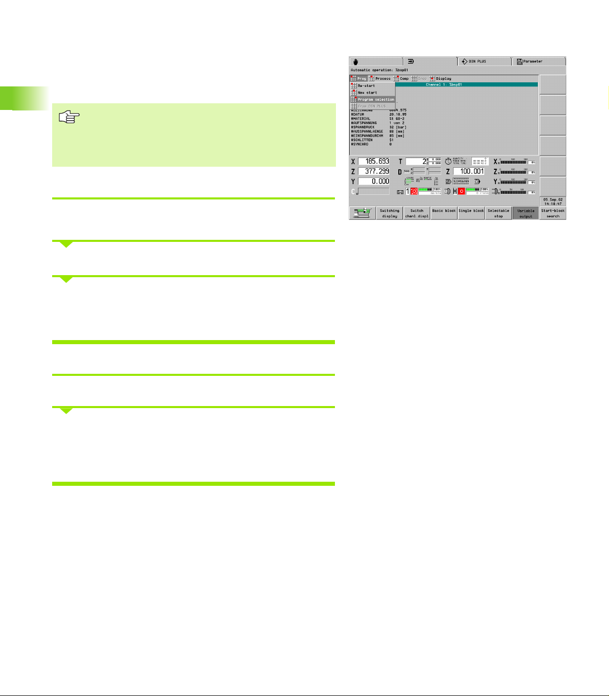
Program selection
The CNC PILOT interprets the NC program before it can be activated
with Cycle Start. “#-Variables” are entered during the translation
process. A “restart” prevents a new translation, while a “new start”
forces a new translation.
If the “turret table” of the NC program is not the
currently valid table, there is a warning.
The name of the NC program is retained until you select
another program, even if the lathe was switched off in
the meantime.
Program selection
3.5 Automatic Mode
Select Prog > Program selection The CNC PILOT opens the list of NC
programs.
Select the NC program
The NC program is loaded without previous translation if:
No changes were made to the program or tool list.
The lathe was not switched off since the program was last selected.
Restart
Select Prog > Restart selection
The most recently active NC program is loaded without previous
translation if:
No changes were made to the program or tool list.
The lathe was not switched off since the program was last selected.
82
Page 83

Start again
Select “Prog > New start”
The NC program is loaded and converted.
(Use for starting an NC program containing # variables.)
From DIN PLUS
Select “Prog > From DIN PLUS”
The NC program selected in DIN PLUS is loaded and converted.
3.5 Automatic Mode
HEIDENHAIN CNC PILOT 4290 83
Page 84

Finding a start block
In the start block search:
Starting at program start, the CNC PILOT complies with the
technology commands but does not conduct a tool change.
The CNC PILOT allows no positioning.
Danger of collision
If the start block includes a T command, the CNC PILOT
first rotates the turret.
The first traversing instruction is executed from the
current tool position.
3.5 Automatic Mode
Mid-program startup
Position the cursor on the start block. (The soft keys support your
search.)
Select a suitable start block on all slides before you
press the Accept soft key.
Activating a start block search
Enter the N number. The cursor is positioned to the
block number
Enter the T number: The cursor is positioned on the
next T command
Enter the L number: The cursor is positioned to the
next subprogram call
The CNC PILOT begins with the start-block search
Starts with the selected NC block
84
Page 85

Modifying the program run
Skip level
The NC blocks with skip levels are not executed when the skip level is
active. The “Skip levels” display field marks the (active) skip levels
detected by the “block execution.“
The CNC PILOT accounts for activated/deactivated skip
levels after approx. 10 blocks (reason: block scan during
the execution of NC blocks).
Activating/deactivating a skip level
Select “Process > Skip level.”
Activating a skip level
Enter the “Level no.” and two or more skip levels as a “sequence of
digits.”
Deactivating a skip level
No entry in “Level no.”
Production with defined quantity
Select “Process > Quantity”
Enter the quantity
Working with defined quantities:
Counting range: 0..9999
The quantity is counted after every program run.
When an NC program is activated with “Program selection,” the
CNC PILOT resets the counter.
When a program has completed the quantity of parts, you can no
longer start the NC program. To start the program again, press “Restart.”
The Quantity remains stored even after the lathe is switched off.
Quantity=0: No limit. The counter counts up the parts.
Quantity > 0: The CNC PILOT manufactures the defined quantity;
the counter counts down the parts.
3.5 Automatic Mode
“Skip levels” display field
Meaning:
Upper row: Entered skip levels
Lower row: Active skip levels
HEIDENHAIN CNC PILOT 4290 85
Page 86

V variables
Working with V variables:
The “V variables” dialog box serves for input and display of
variables.
V variables are defined at the beginning of the NC program. The
meaning is specified in the NC program.
To check or enter a V variable:
Select “Process > V variables”
The CNC PILOT displays the defined variables in the NC program.
3.5 Automatic Mode
Change the variable: Press the Edit button
Single-block mode
In single-block mode, only one NC command (basic block) is executed
at a time. The CNC PILOT then stops the cycle.
Set single-block mode
Activate "Single step" mode.
Cycle Start runs the next NC command
Selectable stop
If the selectable stop is active, the CNC PILOT stops with M01 and
goes into the feed stop condition.
Program run with selectable stop
Activate selectable stop
The CNC PILOT goes with an M01 into the feed stop condition.
Cycle start resumes the program run
86
Status of selectable stop
Selectable stop off
Selectable stop on
Page 87

Feed rate override F%
The programmed feed rate changes with the programmed feed rate
(range of 0 % to 150 %). The machine display shows the current feed
rate override.
Adjusting the feed rate override
Adjust the desired override with the override knob (in the machine
operating panel)
Spindle speed override
With the spindle speed override you can deviate from the
programmed feed rate (range of 50 % to 150 %). The machine display
shows the current spindle speed override.
Adjusting the spindle speed override
Spindle speed at 100% (of the programmed value)
Increase speed by 5%
Reduce speed by 5%
Compensation
Tool compensation
U Select “Comp > Tool compensation”
U T number: The CNC PILOT shows the active T number and the
compensation values. You can enter a different T number.
U Enter the compensation values.
U Values entered here are added to the existing compensation values.
3.5 Automatic Mode
Tool compensation values:
Effective beginning with the next positioning command
Transferred into the database
Can be changed by no more than 1 mm
HEIDENHAIN CNC PILOT 4290 87
Page 88

Additive compensation
U Select “Comp > Tool compensation values”
U Enter the compensation values (901 to 916). The CNC PILOT
displays the valid compensation values.
U Enter the compensation values.
U Values entered here are added to the existing compensation values.
Additive compensation values:
Activated with G149
Managed in the set-up parameter 10
Can be changed by no more than 1 mm
3.5 Automatic Mode
Tool life management
During Automatic mode, in the “tool life management,” switch off and
on the ready-for-use status of a tool, or update the tool life data.
Changing the tool life data
Select Comp > Tool life management.
The CNC PILOT displays the tool list with the current tool life data.
Select the tool location.
Press ENTER. The CNC PILOT opens the “Tool life management”
dialog box.
Select “Ready for use”
Press the “new cutter” button to update the tool life data.
88
Page 89

Inspection mode
For the inspection mode, interrupt the program run, check or correct
the active tool, or change the cutter. Resume the NC program at the
point of interruption.
When the tool is retracted, the CNC PILOT stores the first five traverse
movements. Each change in direction corresponds to a path of
traverse.
Notes on the inspection mode:
During the inspection process you can turn the turret,
press the spindle keys, etc. The return motion program
inserts the “correct” tool.
When changing the cutting edge, select the
compensation values so that the tool stops before the
point of interruption.
In the cycle stop condition you can interrupt the
inspection cycle with the ESC key and switch to
“Manual control.”
The inspection cycle is executed as follows:
1 Interrupt the program sequence and retract the tool.
2 Check the tool and replace the cutting edge if necessary.
3 Retract tool
1. Inspection – Retract the tool
3.5 Automatic Mode
Interrupt the program run
„Select INSPection
To retract the tool, use the manual direction keys.
If necessary, swivel the turret.
HEIDENHAIN CNC PILOT 4290 89
Page 90

2. Inspection – Check the cutting edge
Inspect the tool; if necessary, replace it.
Conclude the inspection process. The CNC PILOT
loads the return motion program (_SERVICE).
The “Tool compensation” dialog box appears. Enter the tool
compensation.
If you are using a new cutting edge, modify the tool compensation so
that the tool—when returning—comes to a stop before the point of
3.5 Automatic Mode
interruption.
If necessary, activate the spindle.
3. Inspection – Return the tool to the work
At the beginning of the returning program, the control asks the two
questions “Scrambled takeoff on restart?” and “Start from/before
interruption point.” Your answers determine the return motion
program as follows:
Scramble takeoff = yes (see 3.1 Return the tool and “scrambled
takeoff”)
Move to point of interruption: The return motion program
positions the tool at rapid traverse to the interruption point and
continues the program without stopping.
Move to before point of interruption: The return motion program
positions the tool in rapid traverse to a position before the
interruption point and continues the program without stopping.
Scramble takeoff = no (see 3.2 Return the tool and stop)
Move to point of interruption: The return motion program
positions the tool to the interruption point and stops the program.
Move to before point of interruption: The return motion program
moves the tool to a position before the interruption point and
stops the program.
“Scrambled takeoff = yes” is usually used when the cutting edge is
not exchanged.
90
Page 91

3.1 Return the tool and “scrambled takeoff”
Start the return motion program.
The “Scrambled takeoff on restart?” dialog box appears. Enter 1
(=yes)
Takeoff from IP:
The “Start from point of interruption (IP)” dialog box appears. Enter 0
(= to IP)
The return motion program positions the tool from/before the
interruption point and continues the program without stopping.
Takeoff before IP:
The “Start from point of interruption (IP)” dialog box appears. Enter 1
(=before IP)
Then, in the “Distance from the interruption point” dialog box, enter
the distance from the point of interruption
The return motion program positions the tool before the interruption
point and continues the program without stopping.
3.5 Automatic Mode
The inspection cycle has been completed.
HEIDENHAIN CNC PILOT 4290 91
Page 92

3.2 Return the tool and stop
Start the return motion program.
The “Scrambled takeoff on restart?” dialog box appears. Enter 0 (=no)
Takeoff from IP:
The “Start from point of interruption (IP)” dialog box appears. Enter 0
(=from IP)
The return motion program positions the tool on/before the
3.5 Automatic Mode
interruption point and stops.
Takeoff before IP:
The “Start from point of interruption (IP)” dialog box appears. Enter 1
(=before IP)
Then, in the “Distance from the interruption point” dialog box, enter
the distance from the point of interruption
The return motion program positions the tool before the interruption
point and stops.
Resume the program run. The inspection cycle has
been completed.
Select “Insp(ection)” again
The “Scratch with tool” dialog box opens (for information)
Assign the handwheel to the X/Z axis and “scratch” the workpiece.
Press “Accept value” to save the compensation values defined per
handwheel.
Resume the program run. The inspection cycle has
been completed.
92
Page 93

If the NC program stops before the interruption point, the
“Distance from the interruption point” comes into play:
If the entered distance is greater than the distance
between the start of the NC block and the interruption
point, program sequence begins at the start of the
interrupted NC block.
If the entered distance is less than the distance
between the start of the NC block and the interruption
point, the CNC PILOT takes the distance into account.
Block display, variable output
The CNC PILOT differentiates between:
Block display: Lists the NC blocks according to the programmed
sequence.
Basic block display: The cycles are “resolved.” Individual paths of
traverse are shown. The numbering of the basic blocks is
independent of the programmed block numbers.
Activate the basic block display:
U Switch on/off the basic block display
Channel display
For lathes with several slides, activate the block display for up to 3
channels.
Switching the channel display:
U Each time the soft key is pressed it connects a
channel. Then only one channel is displayed.
If the block display is active for one channel, the basic
block is shown in the right window. If the block display is active for
two or more channels, the basic block display replaces the block
display.
Font size
The font size of the block display can be adjusted in the menu.
U “Display > Font size > Smaller” reduces the font size
U “Display > Font size > Larger” increases the font size
Variable output
U Pressing the soft key enables the variable soft key
output (with PRINTA). Otherwise the variable output
is suppressed.
Load monitoring display: see “Load Monitoring” on page 100
3.5 Automatic Mode
HEIDENHAIN CNC PILOT 4290 93
Page 94

Graphic display
The “Automatic graphics” function displays the programmed blank
and finished part and the paths of traverse. This enables process
control of non-visible areas during production and provides an
oversight of production status, etc.
All machining operations, including milling, are depicted in the turning
window (XZ view).
U Activate the graphics. If the graphic was already
active, the screen is adapted to the current machining
status.
U Return to block display
3.5 Automatic Mode
With the soft keys shown in the table you can influence the depiction
of traverse.
In the standard setting, the CNC PILOT draws the complete path of
traverse after every block. In the “motion” setting, the cutting process
is shown synchronously to the production process.
If no blank part was programmed, the standard blank
form (control parameter 23) is assumed.
“Motion” must be stopped at the beginning of the NC
program. For program section repeats (M99), motion
start in the next program run.
“Graphic display” soft keys
Set single-block mode
Display of the paths of traverse (see
“Path display” on page 367):
Line, or
Cutting trace
Tool depiction (see “Screen layout,
soft keys” on page 363):
Point of light, or
Tool
Displaying the cutting synchronously
to the production process
94
Page 95

Enlargement, reduction, and selecting a section
Zoom settings by keyboard:
U Activate the magnify function The red rectangle
indicates the new section.
U Adjust the section:
To magnify, use the PgDn key
To reduce, use the PgUp key
To move the frame, use the arrow keys
U Exit the zoom function. The new section is displayed
Zoom settings by touchpad:
U Position the cursor to one corner of the section
U While holding the left mouse key, pull the cursor to the opposite
corner of the section
U Right mouse key: Return to standard size
U Exit the zoom function. The new section is displayed.
After having enlarged a detail to a great extent, select
“Workpiece maximum” or “Work space,” and then
isolate a new detail.
You can make the standard setting by soft key (see table). The “By
coordinates” setting (simulation window and position of the tool zero
point) is given with respect to the selected slides.
Mechatronic tailstock
A moveable opposing spindle can be used as a mechatronic tailstock
if the machine tool builder prepares the machine for this function.
If so, start the sleeve mode with the “Manual PLC” menu item. A
prerequisite is that the Automatic mode was stopped with cycle stop
or that an M0/M01 in the NC program triggered a cycle stop.
3.5 Automatic Mode
“Graphic display” soft keys
Last setting was “workpiece
maximum” or “working space”
Cancels the last magnification
Depicts workpiece in the largest
possible magnification
Depicts the work space including the
tool change position
Set simulation window and position
of the workpiece zero point
HEIDENHAIN CNC PILOT 4290 95
Page 96

Post-process measuring status
Post-process measuring means that the workpiece is measured
outside the lathe and that the results are transferred to the CNC
PILOT. The “PPM Info” dialog box contains information on the status
of the measured values, displays the transferred results, and allows
initialization of communication with the measuring device.
Operation of “post-process measuring”:
U Select Display > PPM Status
U The PPM Info dialog box provides information on the status of the
measured values and the most recently transferred results.
U If you select “Init,” the post-process measuring function is re-
initialized and all measured values are deleted.
3.5 Automatic Mode
PPM Info dialog box:
Measured-value coupling (same as control parameter 10)
Off: Measuring results are immediately transferred. Previous
values are overwritten.
On: Measuring results are not transferred until the previous
results have been processed.
Measured values valid: Status of the measured values (after the
measured values have been transferred with G915, the status “No”
is displayed).
#939: Total result of last measurement
#940..956: Measuring results last transferred by the measuring
function
The post-process measuring function saves the measured
values received in the clipboard. The PPM Info dialog box
displays in #939..956 the values contained in the
clipboard—not the variables.
96
Page 97

3.6 Machine Display
Switching the display
The machine display of the CNC PILOT can be configured. Per slide,
you can configure up to 6 displays in Manual mode and Automatic
mode (starting with control parameter 301).
Switching the display
U Switch to the next configured display.
U Switch to the display of the next slide.
U Switch to the display of the next spindle.
Position display
In “Display type” (MP 17) you set the values of the position display:
0: Actual values
1: Following error
2: Distance of traverse
3: Tool tip with respect to machine zero point
4: Slide position
5: Distance from reference dog to zero pulse
6: Nominal position
7: Difference from tool point to slide position
8: Nominal director position
3.6 Machine Display
Display elements
The following table explains the standard display fields. For further
display fields: see “Control parameters for machine display” on
page 580
Display elements
Position display (distance between tool tip and workpiece zero point)
Empty field: Axis has not been homed
Letter designating the axis appears in white: Axis disabled
Display values shown in gray (only with X or Z): The actual value display is invalid because
the B axis was tilted.
Display of C position
“Index”: marks the C axis “0/1”
Empty box: C axis is not active
Letter designating the axis appears in white: Axis disabled
HEIDENHAIN CNC PILOT 4290 97
Page 98

Display elements
3.6 Machine Display
Distance-to-go display (distance remaining in the current traverse command)
Bar graphic: Distance remaining in millimeters
Field below left: Actual position
Field below right: Distance to go
T display without tool life monitoring
T number of active tool
Tool compensation values
T display with tool life monitoring
T number of active tool
Tool life data
Quantity of workpieces/time per workpiece
Number of finished workpieces in this batch
Production time or current workpiece
Total production time for this batch
Load display
Load of the spindle motors/axis drives with regard to rated torque
D display (additive compensation)
Number of the active compensation
Compensation values
Slide display
Symbol appears in white: Disabled
Cycle status:
Cycle on
Feed stop
Cycle off
Manual control
Inspection cycle
Set-up mode
98
Numeral: Selected slide
White background: No “converting and mirroring” active (G30)
Color background: “Converting and mirroring” active (G30)
Cycle status
Bar graphic: Feed rate override in %
Upper field: Feed rate override
Lower field:
Current feed rate
With stationary slide: Nominal feed rate (gray text)
Slide number on a blue background means the rear face is active
Page 99

Display elements
Spindle status:
Direction of spindle
rotation M3
Direction of spindle
rotation M4
Spindle stop
Spindle in position
control (M19)
C axis is “activated”
Spindle display
Symbol appears in white: Disabled
Numeral in spindle symbol: Gear range
“H”/Numeral: Selected spindle
Spindle status
Bar graphic: Feed rate override in %
Upper field: Spindle speed override
Lower field:
Current speed
With stationary spindle: Nominal speed (gray text)
With position control(M19): Spindle position
Overview of enabled elements
Shows the enabling status of up to 6 NC channels, 4 spindles, and 2 C-axes. Enabled
elements are marked (green).
Display group at left: Enabled
F: Feed rate
D: Data
S: Spindle
C: C axis
1..6: Number of the slide/spindle of the C axis
Display group in center: Status
Zy – left dash: Cycle on/off
Zy – right dash: Feed Stop
R=Reference run
A: Automatic mode
H: Manual control
F: Retracting (after crossing the limit switches)
I: Inspection mode
E: Set-up switch
Display group at right: Spindle
Display for direction of rotation left/right
Both active: Spindle positioning (M19)
3.6 Machine Display
HEIDENHAIN CNC PILOT 4290 99
Page 100

3.7 Load Monitoring
The load monitoring function of the CNC PILOT compares the current
torque, or the values for the work of the drives, with the values from
a reference run.
If “torque limit 1” or the “work limit” is exceeded, the CNC PILOT
marks the tool as worn out. If torque limit 2 is exceeded, the CNC
PILOT assumes tool breakage and stops the machining process (feed
stop). Violations of limit values are reported as error messages.
The load monitoring identifies worn tool in the “tool diagnosis bits.” If
you are using the tool life monitoring function, the CNC PILOT will
manage the replacement of tools. As an alternative, you can evaluate
the tool diagnosis bits in the NC program.
3.7 Load Monitoring
The load monitoring function defines the monitoring zones and the
drives to be monitored (G995) in the NC program. The torque limits of
a monitoring zone depend on the maximum torque determined by the
reference machining cycle.
The CNC PILOT checks the values for torque and work in each
interpolator cycle and displays the values in a time reference grid of
20 ms. The limit values are calculated from the reference values and
the limit factor (control parameter 8). You can later change the limit
values in “Edit load parameters.”
Make sure that the conditions for reference machining
comply with those for production (feed-rate/speed
override, tool quality, etc.).
The CNC PILOT monitors up to four components per
monitoring zone.
Using “G996 Type of load monitoring,” you can control
the hiding the rapid traverses paths and the monitoring
of torque and/or work.
The graphic and numeric displays are relative to the
rated torque values.
100
 Loading...