

Page 1
Page 2

In this user manual we have tried to describe the matters
concerning the operation of this CNC system to the greatest extent.
However, it is impossible to give particular descriptions for all
unnecessary or unallowable operations due to length limitation and
products application conditions;Therefore, the items not presented
herein should be regarded as “impossible” or “unallowable”.
Copyright is reserved to GSK CNC Equipment Co., Ltd. It
is illegal for any organization or individual to publish or reprint this
manual. GSK CNC Equipment Co., Ltd. reserves the right to ascertain
their legal liability.
Page 3

GSK988T Turning CNC System User Manua(Volume Ⅱ)
Preface
Your Excellency,
We are honored by your purchase of this GSK 988 Turning CNC
System made by GSK CNC Equipment Co., Ltd.
This book is User Manual Volume II –“Installation and Debugging”.
To ensure safe and effective running, please read this manual carefully
before installation and operation.
Warning
Accident may occur by improper connection and operation!This
system can only be operated by authorized and qualified personnel.
Special caution:
The power supply fixed on/in the cabinet is exclusively used for the
CNC system made by GSK.
It can't be applied to other purposes, or else it may cause serious
danger!
II
Page 4

Cautions
■ Delivery and storage
● Packing box over 6 layers in pile is unallowed.
● Never climb the packing box, stand on it or place heavy objects on it.
● Do not move or drag the products by the cables connected to it.
● Forbid collision or scratch to the panel and display screen.
● Avoid dampness, insolation and drenching.
■
Open-package inspection
● Confirm that the products are the required ones.
● Check whether the products are damaged in transit.
● Confirm that the parts in packing box are in accordance with the packing list.
Precautions
● Contact us in time if any inconsistence, shortage or damage is found.
■ Connection
● Only qualified personnel can connect the system or check the connection.
● The system must be earthed, and the earth resistance must be less than 0.1Ω.
The earth wire cannot be replaced by zero wire.
● The connection must be correct and firm to avoid any fault or unexpected
consequence.
● Connect with surge diode in the specified direction to avoid damage to the
system.
● Switch off power supply before plugging out or opening electric cabinet.
■ Troubleshooting
● Switch off power supply before troubleshooting or changing components.
● Check the fault when short circuit or overload occurs. Restart can only be done
after troubleshooting.
● Frequent switching on/off of the power is forbidden, and the interval time should
be at least 1 min.
III
Page 5

GSK988T Turning CNC System User Manual (Volume Ⅱ)
ANNOUNCEMENT!
z This manual describes various possibilities as much as possible. However,
operations allowable or unallowable cannot be explained one by one due to
so many possibilities that may involve with, so the contents that are not
specially stated in this manual shall be regarded as unallowable.
WARNING!
z Please read this manual and a manual from machine tool builder carefully
before installation, programming and operation, and strictly observe the
requirements. Otherwise, products and machine may be damaged,
workpiece be scrapped or the user be injured.
CAUTION!
z Functions, technical indexes (such as precision and speed) described in
this user manual are only for this system. Actual function configuration and
technical performance of a machine tool with this CNC system are
determined by machine tool builder’s design, so functions and technical
indexes are subject to the user manual from machine tool builder.
z Though this system adopts standard operation panel, the functions of the
keys on the panel are defined by PLC program (ladder diagram). It should be
noted that the keys functions described herein are for the standard PLC
program (ladder diagram).
z For functions and effects of keys on control panel , please refer to the user
manual from machine tool builder.
This manual is subject to change without further notice.
IV
Page 6

Precautions
Safety Responsibility
Manufacturer’s Responsibility
——Be responsible for the danger which should be eliminated and/or controlled on
design and configuration of the provided CNC systems and accessories.
——Be responsible for the safety of the provided CNC systems and accessories.
——Be responsible for the provided information and advice for the users.
User’s Responsibility
——Be trained with the safety operation of CNC system and familiar with the safety
operation procedures.
——Be responsible for the dangers caused by adding, changing or altering to the
original CNC systems and the accessories.
——Be responsible for the failure to observe the provisions for operation, adjustment,
maintenance, installation and storage in the manual.
This manual is reserved by end user.
We are full of heartfelt gratitude to you for supporting us in the
use of GSK’s products.
V
Page 7

GSK988T Turning CNC System User Manual (Volume Ⅱ)
VI
Page 8

Contents
Contents
CHAPTER I INSTALLATION LAYOUT ..............................................................................................1
1.1 Overall Dimension of GSK988T and Accessories...................................................................1
1.1.1 Overall Dimension of the GSK988T Mainframe............................................................1
1.1.2 Overall Dimension of GSK988T-H Mainframe..............................................................2
1.1.3 Overall Dimension of GSK988T Operation Panel MPU02A .........................................3
1.1.4 Overall Dimension of GSK988T Operation Panel MPU02B .........................................4
1.1.5 Overall Dimension of GSK988T- H Operation Panel MPU03A.....................................5
1.1.6 Overall Dimension of GSK988T-H Operation Panel MPU03B......................................6
1.1.7 Overall Dimension of I/O Deconcentrator MCT01 ........................................................7
1.1.8 Overall Dimension of I/O Deconcentrator MCT02 ........................................................7
1.2 Structure of GSK988T Control System ...................................................................................8
1.2.1 Front /Rear Panel Illustrations......................................................................................8
1.2.2 General Connection Diagram .....................................................................................10
1.3 GSK988T Installation............................................................................................................11
1.3.1 Conditions of Electric Cabinet Installation ..................................................................11
1.3.2 System Grounding Requirements ..............................................................................11
1.3.3 Interference Prevention Methods ...............................................................................11
CHAPTER II INTERFACE SIGNAL DEFINITION AND CONNECTION.............................................13
2.1 Connection with Drive Unit ...................................................................................................13
2.1.1 Definition of the Drive Interface ..................................................................................13
2.1.2 Signal Instruction........................................................................................................13
2.1.3 Connection with the Drive Unit Interface ....................................................................16
2.2 Connection with the Spindle .................................................................................................18
th
2.2.1 The 5
Axis · Spindle Interface Definition ...................................................................18
2.2.2 Signal Instruction........................................................................................................19
2.2.3 Connection with the Servo Spindle Drive Unit ............................................................20
2.2.4 Connection with the Spindle Inverter Interface...........................................................21
2.3 Connection with the Spindle Encoder...................................................................................22
2.3.1 Interface Definition of the Spindle Encoder ................................................................22
2.3.2 Signal Instruction........................................................................................................22
2.3.3 Connection with the Spindle Encoder Interface..........................................................22
nd
2.4 Connection with the 2
2.4.1 Definition of the 2
Spindle............................................................................................23
nd
Spindle (Analog Spindle) Interface ..............................................23
2.4.2 Connection with the 2nd Spindle Inverter Interface .....................................................23
2.5 Connection with MPG...........................................................................................................24
2.5.1 Definition of MPG Interface ........................................................................................24
2.5.2 Signal Instruction........................................................................................................24
2.5.3 Connection with MPG Interface..................................................................................24
2.6 Connection with the Machine Panel .....................................................................................25
2.6.1 Communication Interface Definition............................................................................25
2.7 GSK988T General I/O Interface Definition ...........................................................................25
2.7.1 Definition of Input & Output Addresses.......................................................................25
2.7.2 Input Signal ................................................................................................................26
VII
Page 9

GSK988T Turning CNC System User Manual (Volume Ⅱ)
2.7.3 Output Signal .............................................................................................................27
2.8 Connection with the Power Supply....................................................................................... 28
2.8.1 Definition of Power Supply Interface ..........................................................................29
2.8.2 Connection between GSK988T and GSK-PB2 Power Supply Box ............................ 29
2.9 Connection with the External Equipment..............................................................................29
2.9.1 RS-232 Interface Definition ........................................................................................30
2.9.2 Definition of GSKLINK Bus Interface..........................................................................30
2.9.2 Network Interface Definition .......................................................................................31
2.9.3 USB Interface Definition.............................................................................................31
CHAPTER III MACHINE TOOL DEBUGGING-OPERATION ............................................................32
3.1 Parameter Setting ................................................................................................................32
3.1.1 System Parameters....................................................................................................32
3.1.2 Servo Parameters ......................................................................................................34
3.2 Instruction of PC Communication Software GSKComm-M...................................................37
3.2.1 Preparation for GSKComm-M .................................................................................... 37
3.2.2 File Download (PC→CNC).........................................................................................38
3.2.3 Upload File (CNC→PC) .............................................................................................39
3.3 Usage of U Disk ...................................................................................................................40
3.3.1 File Management Screen ...........................................................................................40
3.3.2 Program Screen .........................................................................................................41
3.3.3 PLC Screen................................................................................................................42
3.4 PLC Operation .....................................................................................................................43
3.4.1 PLC Execution and Stop ............................................................................................44
3.4.2 PLC Monitoring and Diagnosis...................................................................................45
3.4.3 PLC Data Viewing and Setting ...................................................................................48
3.4.4 PLC On-line Modification............................................................................................50
3.4.5 PLC Program Transmission ....................................................................................... 58
3.5 CNC Diagnosis.....................................................................................................................58
3.6 Servo Diagnosis ...................................................................................................................60
CHAPTER IV MACHINE DEBUGGING-FUNCTIONS.......................................................................62
4.1 Emergency Stop and Hardware Limit...................................................................................62
4.2 Basic Axis Parameters Setting .............................................................................................63
4.2.1 Axis Property ..............................................................................................................63
4.2.2 GSKLink Communication Setting of Axis and Servo ..................................................64
4.3 Servo Related Setting ..........................................................................................................65
4.3.1 CNC Servo Parameter Setting ...................................................................................65
4.4 Gear Ratio Adjustment .........................................................................................................66
4.4.1 Gear Ratio Calculation ...............................................................................................67
4.4.2 Gear Ratio Setting......................................................................................................67
4.5 Acceleration/Deceleration Characteristic Adjustment ...........................................................68
4.6 Reference Point and Software Limit .....................................................................................69
4.6.1 Reference Point of Absolute Encoder Setting ............................................................70
4.6.2 Reference Point Setting with Dog ..............................................................................71
4.6.3 Reference Point Setting without Dog .........................................................................72
4.6.4 Setting of Stored Stroke Check ..................................................................................73
VIII
Page 10

Contents
4.7 Pitch Error Compensation ....................................................................................................75
4.8 Backlash Compensation.......................................................................................................78
4.9 Spindle Function Adjustment ................................................................................................80
4.9.1 Spindle Encoder .........................................................................................................80
4.9.2 Spindle Speed Analog Voltage Control .......................................................................81
4.9.3 Double-Spindle Control ..............................................................................................83
CHAPTER V PARAMETER INSTRUCTION ...................................................................................84
5.1 Parameters of System Setting..............................................................................................85
5.2 Parameters of the Interfaces of Input and Output.................................................................85
5.3 Parameters of Axis Control/Setting Unit ...............................................................................85
5.4 Parameters of the Coordinate System..................................................................................89
5.5 Parameters of the Stroke Detection......................................................................................91
5.6 Parameters of the Feedrate..................................................................................................94
5.7 Parameters of Control of Acceleration/Deceleration.............................................................98
5.8 Parameter of Servo and Backlash Compensation..............................................................100
5.9 Parameter of Input/Output ..................................................................................................104
5.10 Parameter of Display and Editing .....................................................................................106
5.11 Parameter of Programming ..............................................................................................109
5.12 Parameters of the Screw Pitch Error Compensation ........................................................ 111
5.13 Parameters of the Spindle Control....................................................................................113
5.14 Parameters of the Tool Compensation .............................................................................117
5.15 Parameters of the Canned Cycle .....................................................................................120
5.15.1 Parameters of the Drilling Canned Cycle ...............................................................121
5.15.2 Parameters of the Thread Cutting Cycle ................................................................121
5.15.3 Parameters of the Combined Canned Cycle ..........................................................121
5.16 Parameters of the Rigid Tapping ......................................................................................123
5.17 Parameters of the Polar Coordinates Interpolation...........................................................125
5.18 Parameters of the User Macro Program...........................................................................126
5.19 Parameters of the Skip Function ......................................................................................127
5.20 Parameters of the Graphic Display...................................................................................128
5.21 Parameter of Run Hour and Parts Count Display.............................................................128
5.22 Parameter of MPG Feed ..................................................................................................129
5.23 Parameter of PLC Axis Control.........................................................................................131
5.24 Parameters of the Basic Function.....................................................................................134
5.25 Parameters of GSKLink Communication Function ...........................................................135
CHAPTER VI STANDARD PLC FUNCTION CONFIGURATION.....................................................136
6.1 Standard Panel on the Machine Tool ..................................................................................136
6.2 Addresses X, Y Definition ...................................................................................................137
6.2.1 General I/O Interface on Machine Tool .....................................................................137
6.2.2 MPG Interface ..........................................................................................................141
6.2.3 Spindle Interface .....................................................................................................142
6.2.4 Standard Operation Panel........................................................................................143
6.3 Standard PLC Functions.....................................................................................................147
6.3.1 Cycle Start and Feed Hold........................................................................................147
6.3.2 Feed/Spindle Hold....................................................................................................148
IX
Page 11

GSK988T Turning CNC System User Manual (Volume Ⅱ)
6.3.3 Program Lock...........................................................................................................149
6.3.4 Feedrate Override ....................................................................................................149
6.3.5 Spindle Override.......................................................................................................149
6.3.6 Spindle CCW/CW Control ........................................................................................ 150
6.3.7 Spindle Jog...............................................................................................................151
6.3.8 Spindle 8-Point Pre-Orientation................................................................................152
6.3.9 Spindle Speed Binary Control...................................................................................154
6.3.10 Spindle Gear Control.............................................................................................. 154
6.3.11 Cooling Control....................................................................................................... 155
6.3.12 Lubricating Control .................................................................................................156
6.3.13 Chuck Control ........................................................................................................157
6.3.14 Tailstock Control .....................................................................................................158
6.3.15 Low Pressure Detection .........................................................................................159
6.3.16 Overtravel Signal of Axes....................................................................................... 160
6.3.17 Tool Change Control...............................................................................................160
6.3.18 Emergency Stop.....................................................................................................165
6.3.19 Tri-Colored Lamp ...................................................................................................166
6.4 Standard PLC Parameter Instruction..................................................................................166
6.4.1 Parameter K ............................................................................................................. 166
6.4.2 Parameter DT...........................................................................................................167
6.4.3 Parameter DC .......................................................................................................... 168
6.4.4 Parameter D.............................................................................................................169
6.5 Signals G, F Used in Standard PLC....................................................................................169
6.5.1 Signal G ...................................................................................................................169
6.5.2 Signal F....................................................................................................................171
APPENDIX A ALARM LIST ..........................................................................................................173
A.1 Program Alarms (P/S Alarms)............................................................................................173
A.2 Parameter Alarms ..............................................................................................................183
A.3 Pulse Encoder Alarms........................................................................................................184
A.4 Servo Alarms .....................................................................................................................184
A.5 Overtravel Alarms ..............................................................................................................185
A.6 Spindle Alarms...................................................................................................................185
A.7 System Alarms...................................................................................................................185
A.8 PLC Alarms........................................................................................................................186
A.9 GSKLink Communication Prompts.....................................................................................188
A.10 Servo Inner Alarms ..........................................................................................................189
APPENDIX B MOTOR TYPE CODE LIST....................................................................................193
B.1 DAT2000C Series Motor Model Code List .........................................................................193
B.2 DAP03C,DAY3025C Model Code List ...............................................................................194
APPENDIX C COMMON ALARM REMEDY ................................................................................. 195
C.1 CNC Common Alarm Remedy........................................................................................... 195
C.2 DAT Feed Servo Alarm Remedy........................................................................................ 195
C.3 Spindle Servo Alarm Remedy ............................................................................................201
X
Page 12

Chapter I Installation Layout
CHAPTER I INSTALLATION LAYOUT
1.1 Overall Dimension of GSK988T and Accessories
1.1.1 Overall Dimension of the GSK988T Mainframe
1
Page 13
GSK988T Turning CNC System User Manual (Volume Ⅱ)
1.1.2 Overall Dimension of GSK988T-H Mainframe
Note: The panel of GSK988T-H is horizontal.
2
Page 14

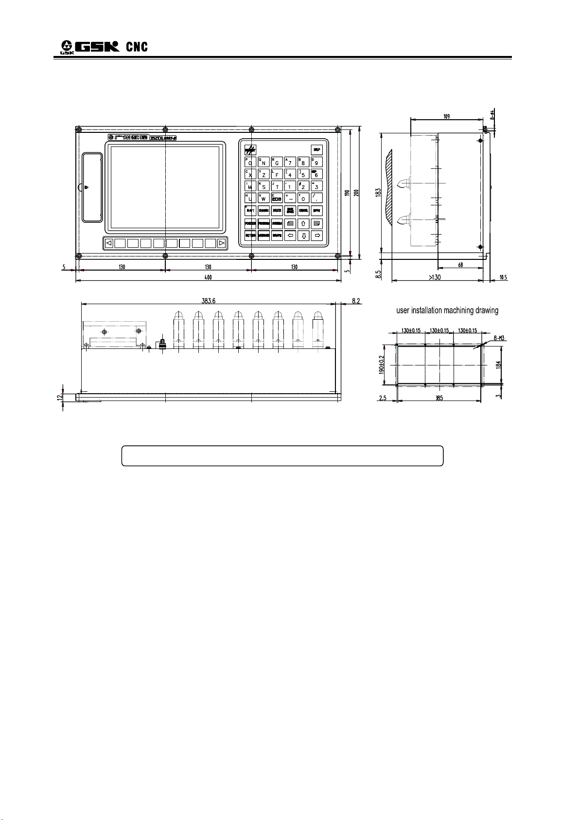
Chapter I Installation Layout
1.1.3 Overall Dimension of GSK988T Operation Panel MPU02A
0
9
0
1
0
2
0
3
0
0
8
0
7
0
6
0
4
50
30
3
Page 15
GSK988T Turning CNC System User Manual (Volume Ⅱ)
1.1.4 Overall Dimension of GSK988T Operation Panel MPU02B
30
4
Page 16

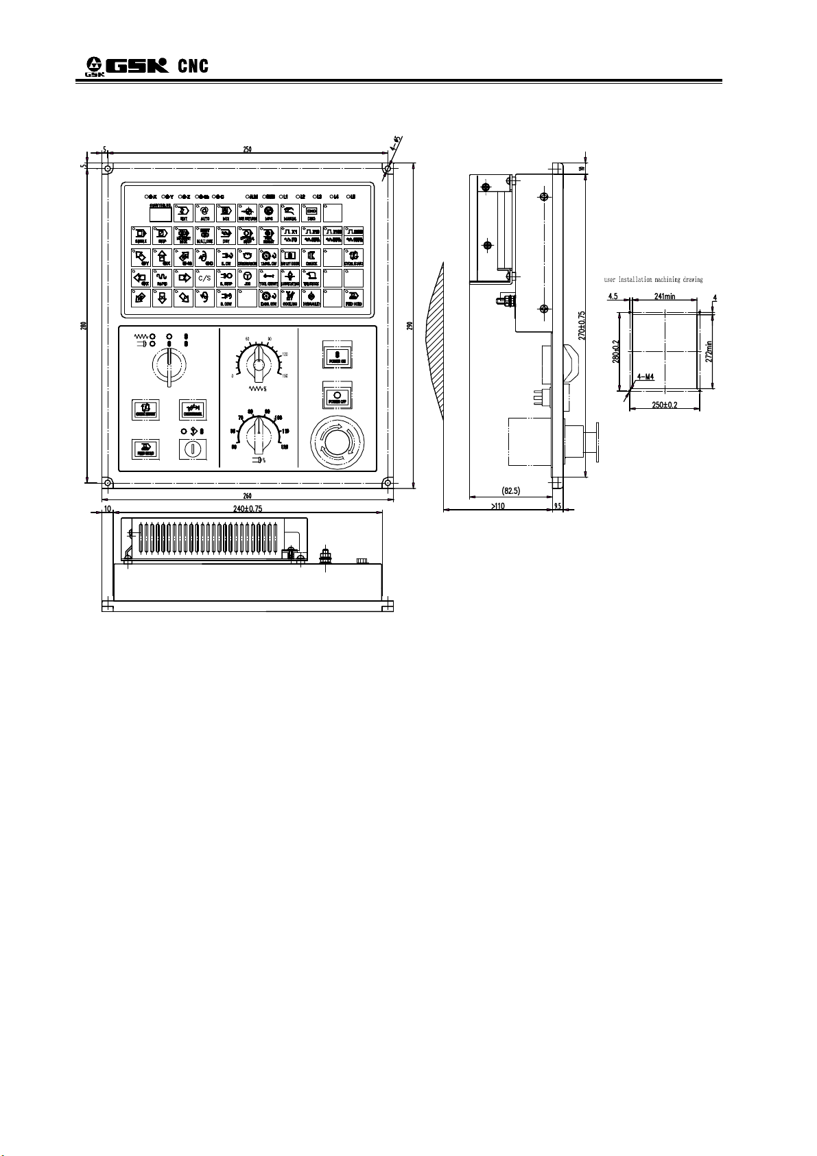
Chapter I Installation Layout
1.1.5 Overall Dimension of GSK988T- H Operation Panel MPU03A
30
5
Page 17

GSK988T Turning CNC System User Manual (Volume Ⅱ)
1.1.6 Overall Dimension of GSK988T-H Operation Panel MPU03B
30
6
Page 18

Chapter I Installation Layout
1.1.7 Overall Dimension of I/O Deconcentrator MCT01
1.1.8 Overall Dimension of I/O Deconcentrator MCT02
7
Page 19

GSK988T Turning CNC System User Manual (Volume Ⅱ)
1.2 Structure of GSK988T Control System
1.2.1 Front /Rear Panel Illustrations
Connect to spindle encoder
ENCODER ENCODER 2
CN21
ST
1 AXIS
CN11
COM WITH
MACHINE PANEL
+24V
0V
-12V
0V
+12V
0V
+5V
+5V
+5V
CN1
MPG
GSKLINK(A)
CN53
CN31CN22
ND RD TH
CN12
3 AXIS 2 AXIS
4 AXIS
CN13 CN14
INPUT OUTPUT
CN54
CN61 CN62
GSKLINK(B)
CN52
ND
2 SPINDLE
CN41
TH
5 AXIS SPINDLE
CN15
Connect to spindle encoder 2
(It can be used as the 2nd MGP)
Used for communication between
CNC and remote I/O unit
Used for communication between
CNC and servo drive uni
Connect to MPG
Connect to the 2nd spindle
Feed axis interface (connect to
the 1~4 axes servo drive unit)
Output interface from CNC
to machine tool
Connect to spindle servo
drive unit/invertor/the 5th
axis servo drive unit
Input interface from
machine tool to CNC
Connect to machine tool panel
8
Power supply interface
Fig. 1-2-1 The layout of GSK988T mainframe rear cover interfaces
Note: These interfaces are compatible with GSK988T-H system. See Fig.1-2-1
Page 20

Chapter I Installation Layout
ENCODER ENCODER 2
CN21
CN22
AXIS 2AXIS 1
MPG
CN31
AXIS 3
GSKLINK(A)
CN53
AXIS 4
CN14CN13CN11 CN12
GSKLINK(B)
CN52
SPINDLE 2
CN41
MACHINE PANEL
CN54
AXIS 5 SPINDLE
CN15
INPUT OUTPUT
+24V
0V
-12V
0V
+12V
0V
+5V
+5V
+5V
CN61CN62
CN1
Fig. 1-2-2 The layout of GSK988T-H mainframe rear cover interfaces
Fig. 1-2-3 The layout of GSK988T front panel interfaces
9
Page 21

GSK988T Turning CNC System User Manual (Volume Ⅱ)
1.2.2 General Connection Diagram
GSK 988T
10
Fig. 1-2-4 GSK988T connection diagram
Page 22

Chapter I Installation Layout
1.3 GSK988T Installation
1.3.1 Conditions of Electric Cabinet Installation
¾ Prevent the entry of dust, coolant and organic solution.
¾ The distance between CNC rear cover and the cabinet should not be less than 20cm.
Ensure that the temperature difference (outside and inside the cabinet) will be less than
10℃ in case of temperature rising in the cabinet.
¾ A radiator fan can be installed inside the cabinet to ensure ventilation.
¾ The display panel should be installed in proper place to avoid the coolant ejection.
¾ The interference of external electrical equipments to the CNC should be taken into
consideration and be reduced to the greatest extent.
1.3.2 System Grounding Requirements
The following grounding systems are for CNC machine tool:
¾ Signal ground
It provides the reference voltage of telecommunication system (0V).
¾ Frame ground
It is used for the sake of safety. The shell of frame unit, panel and the interface cables
shield should be connected together. It can also suppress the internal and external
noise.
¾ System ground
It is used to connect the devices and the frame ground with the ground.
Note 1: The connection between signal and frame ground in the CNC control unit is only made at one
place.
Note 2: Use the AC power line with grounding wire to ensure grounding during power supply.
1.3.3 Interference Prevention Methods
Measures such as shielding electromagnetic radiation, absorbing impulse current and
filtering power noise are taken into CNC design, which, to some extent, protects the CNC to
external interference. To ensure a steady working of CNC, it is necessary to take following
measures during CNC installation:
① Keep CNC far away from the interference source (such as inverter, AC contactor, static
generator, high pressure generator and sectioning for power line, etc.)
② The power to CNC should be supplied via insulation transformer; the machine installed
with CNC should be grounding; the CNC and drive unit should be connected with
independent grounding wire via grounding point.
③ Interference suppression: connect the RC circuits parallelly at two ends of the AC coil;
the RC circuit should be installed to the inductive load as near as possible; fly-wheel
diode should be inversely connected in serial at two ends of the DC coil ; surge absorber
should be connected in parallel at the winding head of AC motor (see Fig. 1-3-1).
11
Page 23

GSK988T Turning CNC System User Manual (Volume Ⅱ)
Fig. 1-3-1
④ The outgoing cable of CNC is twisted shielded cable or shielded cable; the shielding
layer of the cable is single-end earthed at CNC side; the signal line should be as short
as possible.
⑤ To reduce the interference between CNC signal cables and high-voltage cable, the
following principles should be followed when wiring:
Group Cable type Group Cable type
AC power line DC coil (24VDC)
A
C
Wiring Requirements:
¾ The cable should be twisted pair.
¾ Bundle the cables of group A separately from the cables in groups B, C, and the distance
should be no less than 10cm; or, make electromagnetic shielding for the cables in group A.
¾ Bundle the cables of group C separately from the cables in group A, and the distance should
be no less than 10cm; or, make electromagnetic shielding for the cables in group C; the
distance between group C cables and group B cables should be no less than 10cm.
¾ Bundle the cables of group B separately from the cables in group A; or, make
electromagnetic shielding for the cables in group B; cables in group B should be bundled
separately from the group C cables as far as possible.
Cables between CNC and servo
AC coil DC relay (24VDC)
Cables between CNC and high-voltage
AC contactor
drive unit
B
electric cabinet
Cables between CNC and machine tool
12
Page 24

Chapter II Interface Signal Definition and Connection
CHAPTER Ⅱ INTERFACE SIGNAL DEFINITION AND
CONNECTION
2.1 Connection with Drive Unit
2.1.1 Definition of the Drive Interface
1:nCP+
2:nDIR+
3:nPC
4:+24V
5:nALM
6:nSET
7:nEN
Fig. 2-1-1 CN11, CN12, CN13 and
CN14 interfaces (15 pins, D-type
注:n 代表 1、2、3 或 4, 以下相同;
female)
Note: CN1 is the 1st servo axis interface, CN2 is the 2nd one, CN3 the 3rd one, and CN4 the 4th one. Each
controlled axis outputs the corresponding servo axis interface, which is set by parameter NO.1023.
9: nCP-
10:nDIR11:0V
12:+5V
13:+5V
14:0V
15:0V
Signal Description
nCP+、nCP-
nDIR+、nDIR-
nPC Zero point signal
nALM Drive unit alarm signal
nEN Axial enable signal
nSET Pulse inhibition signal
nRDY Servo ready signal
Command pulse signal
Command direction signal
2.1.2 Signal Instruction
(1) Command pulse signal and nCP and command direction signal nDIR
nCP+ and nCP- are command pulse signals, nDIR+ and nDIR- are command direction
signals, the two groups of signals all are difference (AM26LS31) output, the external is suggested
to use AM26LS32 for receiving, refer to the following Fig.2-1-2 about the internal circuit:
Fig. 2-1-2 Internal circuit of nCP and nDIR
(2) Drive unit alarm signal nALM
The drive alarm level is low or high, which is set by 0 bit of parameter 1816; refer to Fig.2-1-3
for the internal circuit.
13
Page 25

GSK988T Turning CNC System User Manual (Volume Ⅱ)
Fig. 2-1-3. Internal circuit of nALM
Input circuit of this type requires that the drive should provide the signal through the methods
in the following Fig. 2-1-4:
Method 1: Method 2:
Fig. 2-1-4. Methods of the drive unit providing signals
(3) Servo ready signal nRDY
nRDY signal is connected to the servo drive unit ready signal. See Fig. 2-1-5.
(4) Axial enable signal nEN
When CNC is running normally, nEN signal output is valid (nEN signal connects with 0V),
and the drive or the emergency stop alarms, CNC switched off, nEN signal outputs (nEn signal
cuts off 0V). About the internal interface circuit, refer to the following Fig. 2-1-6:
Fig. 2-1-5 Internal circuit of nRDY
Fig. 2-1-6. Internal circuit of nEN
(5) Pulse inhibition signal nSET
nSET signal indicates the servo input inhibition. To improve the anti-interference ability
between CNC and the drive, the signal is low-level when CNC outputs the pulse signal, if there
14
Page 26
Chapter II Interface Signal Definition and Connection
isn’t any pulse signals, it is high level; refer to the following Fig. 2-1-7 about the internal interface
circuit:
Fig. 2-1-7 Pulse forbidden signal circuit
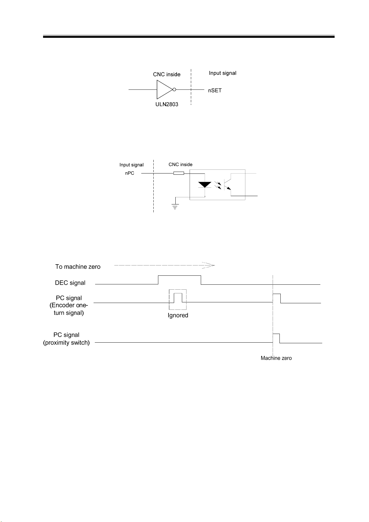
(6) Zero point signal nPC
Take one-rotation signal of motor encoder or proximity switch signal as zero signals. About
the internal connection circuit, refer to Fig. 2-1-8:
Fig. 2-1-8 Zero point signal circuit
① The illogram of PC signals provided by user is shown in Fig. 2-1-9:
Fig. 2-1-9 Signal illogram
Note: During machine zero return, after releasing the deceleration switch, CNC determines the position of
the reference point through detecting PC signal jumping, and the rising edge check and the falling
edge check are both valid.
② Refer to Fig. 2-1-10 for the connection method of taking one NPN-type Hall unit as the
deceleration signal:
15
Page 27

GSK988T Turning CNC System User Manual (Volume Ⅱ)
Fig. 2-1-10 Connection with NPN-type Hall unit
③ Refer to the following Fig. 2-1-11 about the connection method of taking one Hall unit in
PNP type as one deceleration signal:
Fig. 2-1-11 Connection with Hall unit in PNP type
2.1.3 Connection with the Drive Unit Interface
The connection between GSK988T system and GSK DA98B drive unit is shown in the
following figure.
16
Page 28

Chapter II Interface Signal Definition and Connection
Fig. 2-1-12 Connection between GSK988T and DA98B
The connection between GSK988T and GSK DAT2000C drive unit is shown as follows:
Fig. 2-1-13 Connection between GSK988T and DAT2000C drive unit
17
Page 29

GSK988T Turning CNC System User Manual (Volume Ⅱ)
2.2 Connection with the Spindle
The spindle interface of GSK988T is CN15 (the fifth axis · spindle interface). It is equipped
with the function of pulse output and analog voltage output, and can be adopted with the servo
th
spindle drive unit or the common spindle Inverter, or taken as an independent 5
servo axial
interface. Moreover, GSK988T system is also equipped with the 2nd spindle interface CN41 (refer
to following chapters for details), and it can output 0~+10V analog voltage for extending the 2
nd
spindle or the power unit.
2.2.1 The 5th Axis · Spindle Interface Definition
1:SCP+
2:SDIR+
3:GND
4:SALM
5:X5.0(VPO)
6:X5.1(SAR/PAR)
7:SRDY
8:X5.2(ZSP)
9:GND
10:SPC
11:+24V
12:AGND
13:SVC
Fig. 2-2-1 CN15 servo spindle interface (25 cords, D type female)
14:SCP15:SDIR16:GND
17:+24V
18:SSET
19:SEN
20:Y5.0(VP)
21:Y5.1(TAP)
22:Y5.2(SFR)
23:Y5.3(SRV)
24:GND
25:AGND
18
Page 30

Chapter II Interface Signal Definition and Connection
Signal
Definition
SCP+, SCP-
SDIR+,SDIR-
SALM Drive unit alarm signal /
SRDY
SSET
SEN
SPC
SVC
AGND
X5.0 (VPO)
X5.1 (SAR/PAR)
X5.2 (ZSP)
Y5.0 (VP)
Y5.1 (TAP) Address of PLC signal, binary output
Y5.2 (SFR)
Y5.3 (SRV)
+24V
GND
Command pulse signal
Command direction signal
Servo ready signal
Pulse forbidden signal
Axial enable signal
Zero point signal
0~+10V analog voltage output
Analog voltage output ground
Address of PLC signal, binary input
Address of PLC signal, binary input
Address of PLC signal, binary input
Address of PLC signal, binary output
Address of PLC signal, binary output
Address of PLC signal, binary output
+24V
0V (binary input & output signal ground ) /
Explanation
Function Defined by Standard
Spindle speed/position status signal
Spindle position/speed reaching signal
Spindle output at zero speed signal
Spindle speed/position switch signal
Spindle speed loop gain selection
signal 2 (used for tapping)
PLC Address
/
/
/
/
/
/
/
/
Spindle CW signal
Spindle CCW signal
/
2.2.2 Signal Instruction
In the 5th axis • spindle interface, the internal circuits of SCP+, SCP-, SDIR+, SDIR-, SALM,
SRDY, SSET, SEN are consistent with that of the similar signal in the drive interfaces CN11,
CN12, CN13, CN14. Refer to section 2.1.2.
(1) Zero point signal SPC
SPC signal is valid at low level. It is different with the nPC signal in CN11, CN12, CN13,
CN14 interfaces (high-level nPC signal is valid). The internal circuit of SPC is shown in Fig. 2-2-2:
Fig. 2-2-2 Internal circuit of SPC
(2) Signals X5.0, X 5.1, X 5.2, X 5.3, X5.4
Signals X5.0, X 5.1, X 5.2, X 5.3, X 5.4 are the PLC signal addresses; binary input; the
internal circuit is shown in Fig.2-2-3.
19
Page 31

GSK988T Turning CNC System User Manual (Volume Ⅱ)
Fig.2-2-3
Note: In the 5th axis • spindle interface, low-level signals X5.0, X5.1, X5.2, X5.3, X5.4 are valid. The X
address in general input CN61 (X0.0~X0.7, X1.0~X1.7, X2.0~X2.7, X3.0~X3.7) are valid during
high-level input.
(3) Signals Y5.0, Y 5.1, Y 5.2, Y 5.3, Y 5.4
Signals Y5.0, Y 5.1, Y 5.2, Y 5.3, Y 5.4 are the PLC signal addresses; binary output. The
internal circuit is shown in Fig. 2-2-4:
Fig. 2-2-4
2.2.3 Connection with the Servo Spindle Drive Unit
Connection between GSK988T and GSKDAP03C servo spindle drive unit is shown in the
following figure. This connection can also be applied in spindle servo drive unit such as GSK
DAP03/DAY3025C/DAY3025/DAY3100.
20
Page 32

Chapter II Interface Signal Definition and Connection
Fig. 2-2-5 Connection between GSK988T and DAP03C drive unit
2.2.4 Connection with the Spindle Inverter Interface
The 5th axis ·spindle interface (CN15) SVC port outputs 0~+10V voltage, the connection
between GSK988T and the spindle inverter is shown in the following figure:
Fig. 2-2-6 Connection between GSK988T and inverter
21
Page 33

GSK988T Turning CNC System User Manual (Volume Ⅱ)
2.3 Connection with the Spindle Encoder
GSK988T is equipped with two-channel encoder input interfaces (CN21 and CN22), CN21
interface is used as feedback input of spindle speed by default. When multi-spindle control
function is started, select the encoder interface which receives the feedback pulse for the system
control, through the selection signal PC2SLC (G28.7) of spindle encoder in PLC. When the
interface (CN22) of encoder 2 does not connect to the encoder and the selection signal PC2SLC
of the position encoder is not set to 1, CN21 interface is taken as the feedback input of the
spindle speed.
2.3.1 Interface Definition of the Spindle Encoder
8:PAS/HA1
7:*PAS
6:PBS/HB1
5:*PBS
4:PCS
3:*PCS
2:
1:
15:0V
14:0V
13:+5V
12:+5V
11:0V
10:
9:
Fig. 2-3-1 Encoder interface of CN21
and CN22 (15 pins, D-type, male)
Signal Description
*PAS/PAS Encoder phase A pulse
*PBS/PBS Encoder phase B pulse
*PCS/PCS Encoder phase C pulse
The 2
HA1 (Only CN22 is
with the signal)
HB1 (Only CN22 is
with the signal)
(When it’s not used in the 2
spindle encoder, it can be used
The 2
(When it’s not used in the 2
spindle encoder, it can be used
phase A signal
to extend the 2
nd
MPG phase B signal
to extend the 2
nd
MPG
nd
nd
MPG)
MPG.)
nd
nd
2.3.2 Signal Instruction
*PCS/PCS, *PBS/PBS and *PAS/PAS are difference input signals of phase C, B and A
respectively; *PAS/PAS and *PBS/PBS is the orthogonal square wave with difference of 90°, the
maximum signal frequency <1MHz: The quantity of GSK988T encoder pulses is set by parameter
nd
No.3773 (the quantity of the spindle encoder pulses) and No.3803 (the quantity of the 2
spindle
encoder).
2.3.3 Connection with the Spindle Encoder Interface
The connection between GSK988T and the spindle encoder with the twisted pair line is
shown in Fig. 2-3-2, and Changchun Yiguang ZLF-12-102.4BM-C05D encoder is taken as one
example:
22
Page 34

Chapter II Interface Signal Definition and Connection
Changchun
GSK988T(CN21、CN22)
*PC
3
S
Yiguang 1024
encoder
8
ZZ
PCS
4
*PB
S
5
PBS
6
7
8
11
*PA
PAS
0
+5V
S
V
12
Metal cabinet
Fig. 2-3-2 Connection between GSK988T and the encoder
2
6
3
7
5
4
11
B
B
AA
0
V
+5V
2.4 Connection with the 2nd Spindle
988T supports multi-spindle function. Two spindle analog voltage output interfaces include
5th axis ·spindle (CN15) interface and the 2nd spindle (CN41) interface. They are controlled by
nd
PLC signals. The 2
spindle interface can be used to the 2nd inverter spindle or the unit head.
2.4.1 Definition of the 2nd Spindle (Analog Spindle) Interface
5:SVC
4:GND
3:Unused
2:Unused
1:Unused
CN41 analog spindle interface
(9pins, D-type, male)
1
Fig.2-4-1
6
9:Unused
8:Unused
7:Unused
6:Unused
Signal Description
SVC 0~+10V analog voltage output
GND analog voltage output ground
2.4.2 Connection with the 2nd Spindle Inverter Interface
The 2nd spindle interface SVC port outputs 0~10V voltage. The connection is shown in Fig.
2-4-2:
Fig. 2-4-2 Connection between GSK988T and the 2
nd
spindle inverter
23
Page 35

GSK988T Turning CNC System User Manual (Volume Ⅱ)
2.5 Connection with MPG
2.5.1 Definition of MPG Interface
9: X6.3
8: X6.2
7: Unused
6: X6.1
5: X6.0
4: HB3: HB+
2: HA1: HA+
Fig. 2-5-1 CN31 MPG interface
(26 pins, D-type male)
18: +24V
17: +24V
16: +5V
15: +5V
14: +5V
13: 0V
12: 0V
11: 0V
10: 0V
26: X7.0
25: X6.7
24: X6.6
23: X6.5
22: X6.4
21: Unused
20: Unused
19: Unused
Signal Description
HA+, HA- MPG phase A signal input
HB+, HB- MPG phase B signal input
X6.0~X7.0
PLC signal address; binary
input
2.5.2 Signal Instruction
HA+, HA- and HB+, HB- are difference input signals of MPG phase A and B respectively.
X6.0~X7.0 interfaces are input addresses defined by PLC interface, and it can also be used for
axial selection of external MPG box and gear signal input.
Fig. 2-5-2 Inside circul of X6.0~X7.0 signal
2.5.3 Connection with MPG Interface
The typical connection between GSK988T and MPG is shown as the following figure:
24
Page 36

Chapter II Interface Signal Definition and Connection
2.6 Connection with the Machine Panel
Connect between GSK988T system and the machine panel through communication.
2.6.1 Communication Interface Definition
Fig. 2-6-1 Standard machine panel interface CN54
(15 pins, D-type male)
Pin No. Signal IN/OUT Description
1 RXDA IN Receive data difference signal
2 RXDB IN Receive data difference signal
4 TXDA OUT Send data difference signal
5 TXDB OUT Send data difference signal
7 RESET OUT Panel resetting signal
2.7 GSK988T General I/O Interface Definition
2.7.1 Definition of Input & Output Addresses
Table 2-11 Definition of input & output addresses
Interface
CN61 (male)
input
CN61
Pin No.
1 X0.0 1 Y0.0
2 X0.1 2 Y0.1
3 X0.2 3 Y0.2
4 X0.3 4 Y0.3
5 X0.4 5 Y0.4
6 X0.5 6 Y0.5
7 X0.6 7 Y0.6
8 X0.7 8 Y0.7
9 X1.0 9 Y1.0
10 X1.1 10 Y1.1
11 X1.2 11 Y1. 2
12 X1.3 12 Y1.3
13 X1.4 13 Y1.4
14 X1.5 14 Y1.5
15 X1.6 15 Y1.6
16 X1.7 16 Y1.7
29
30
31
32
33
PLC
Address
X2.0
X2.1
X2.2
X2.3
X2.4
Interface
CN62 (female)
output
CN62
Pin No.
29
30
31
32
33
PLC
Address
Y2.0
Y2.1
Y2.2
Y2.3
Y2.4
25
Page 37

GSK988T Turning CNC System User Manual (Volume Ⅱ)
34
35
36
37
38
39
40
41
42
43
44
17
18
19
20
25
26
X2.5
X2.6
X2.7
X3.0
X3.1
X3.2
X3.3
X3.4
X3.5
X3.6
X3.7
X4.0
X4.1
X4.2
X4.3
X4.4
X4.5
34
35
36
37
38
39
40
41
42
43
44
17~19, 26~28
20~25
Y2.5
Y2.6
Y2.7
Y3.0
Y3.1
Y3.2
Y3.3
Y3.4
Y3.5
Y3.6
Y3.7
0V
+24V
27
28
21~24
X4.6
X4.7
0V
2.7.2 Input Signal
Input signal is the one which the machine electric wire or the machine panel transmits to
CNC, and after connecting the input signal and +24V, the input is valid; if they are cut off, the
input is invalid. The input signal of contacts on the machine side should satisfy the following
conditions:
Contact capacity: DC30V, 16mA above;
Leakage current between contacts during opening: Below 1mA;
Voltage drop between contacts during closing: Below 2V (Current 8.5mA, including the cable
potential drop).
There are two methods of external input for input signals: one is switch input with contacts,
the connection is shown in Fig. 2-7-1:
26
Fig. 2-7-1
Page 38

Chapter II Interface Signal Definition and Connection
The other is switch (transistor) input free of contacts; connection is shown in Fig. 2-7-2 and
Fig. 2-7-3.
Fig. 2-7-2 NPN type
Fig. 2-7-3 PNP type
2.7.3 Output Signal
Output signal is used for the drive machine electrical wire side or the relay and the indicator
on the machine panel side. When the output signal connects with 0V, the output function is valid
(Y output signal is 1); cut off 0V, the output function is invalid (Y output signal is 0). The circuit is
shown in the following Fig. 2-7-4:
Fig. 2-7-4. Internal circuit of the output signals
Therefore, the signal has two output statuses: OV output or high resistance. The typical
application is as below:
z Drive light diode
Use ULN2803 to output drive light diode and need the serial connection with one resistance,
27
Page 39

GSK988T Turning CNC System User Manual (Volume Ⅱ)
limit the current from light diode (normally 10mA), which is shown in Fig. 2-7-5:
Fig. 2-7-5: Drive light diode
z Indicator in drive filament type
ULN2803 is used to output the indicator in drive filament type, and externally connect with
one preheated resistance to reduce the current shock during break-over, and the value of the
preheated resistance is based on that the indicator is off, which is shown in Fig. 2-7-6:
Fig. 2-7-6
z Drive inductive loading (such as the relay)
Output the drive inductive loading in ULN2803 type and it requires connecting the fly-wheel
diode close to the circuit, which is to protect the output circuit and reduce the interference, which
is shown in Fig. 2-7-7:
Fig. 2-7-7
2.8 Connection with the Power Supply
GSK988T uses GSK-PB2 power supply box, There are 4 groups of voltage: +5V (3A), +12V
(1A), -12V (0.5A) and +24V (0.5A), and common port COM (0V).
28
Page 40

Chapter II Interface Signal Definition and Connection
2.8.1 Definition of Power Supply Interface
The interfaces of power supply are shown in Fig. 2-8-1 and 2-8-2:
+24V
0V
-12V
0V
+12V
0V
+5V
+5V
+5V
Fig. 2-8-1 power supply interface CN1 Fig. 2-8-2 power supply interface on the panel
2.8.2 Connection between GSK988T and GSK-PB2 Power Supply Box
When GSK988T is dispatched from the factory, GSK-PB2 power supply box and GSK988T
power supply interface has been already connected, so the user just need to connect to 220V AC
power supply. The connection between GSK-PB2 power supply box and GSK988T power supply
interface is shown in Fig. 2-8-3:
Fig. 2-8-3
2.9 Connection with the External Equipment
There are three interfaces on the left side of GSK988T LCD display screen: USB (flash
driver), internet and RS-232 interfaces, which are shown in the following figure. All the three
interfaces can be used for processing the file, two-way transmission between the system Para file
and PLC file and upgrading the system software. Among them, the internet interface can also be
used for remote monitor from PC to 988T system.
29
Page 41

GSK988T Turning CNC System User Manual (Volume Ⅱ)
USB interface
Internet interface
RS-232 interface
Fig. 2-9-1 GSK988T front panel interface
2.9.1 RS-232 Interface Definition
RS-232 communication interface:
1
5: GND
4:
3: TXD
2: RXD
1:
6
9:
8:
7:
6:
Fig. 2-9-2 RS-232 interface
(9 holes, D type female )
GSK988T executes communication through RS232 with PC (GSKComm-M communication
software should be installed). The connection is shown in Fig. 2-9-3:
Pin No. Signal
2 RXD
3 TXD
5 GND
Fig. 2-9-3 Connection between GSK988T and PC
2.9.2 Definition of GSKLINK Bus Interface
GSK988T is with GSKLink interfaces of two routes for connecting with the remote IO units
and the servo drive unit with GSKLink communication function. Among them, CN53 (GSKLINK
serial bus A) is for communication between CNC and the servo drive unit to realize real-time
monitor of servo parameter configuration and servo unit; CN52 (GSKLINK serial bus B) is for
30
Page 42

Chapter II Interface Signal Definition and Connection
communication between CNC and remote IO unit.
1:GND
2:CANn_L
3:
4:GND
1
6
6:
7:CANn_
8:
9:
H
5:
Fig 2-9-4 GSKLink bus interface CN53 and
CN52 (9 holes, D type female)
2.9.2 Network Interface Definition
Network interface (standard):
Pin No. Signal Pin No. Signal
1 TXDLAN+ 9 LINK_LED
2 TXDLAN- 11 LAN_LED
3 RXDLAN+ 10, 12 VDD33
6 RXDLAN- 13, 14 Chassis ground
Signal Description
CANn_L
Low level of data
difference signal
CANn_H High level of data
difference signal
GND Signal ground
2.9.3 USB Interface Definition
Main USB interface (standard):
Pin No. Signal
1
2
3
4
5, 6
VCC(+5V)
USB_DN0
USB_DP0
GND
Chassis ground
31
Page 43

GSK988T Turning CNC System User Manual (Volume Ⅱ)
CHAPTER III MACHINE TOOL DEBUGGING-OPERATION
3.1 Parameter Setting
The modification, backup and recovery of GSK988T system parameters and servo parameters
can only be done under such conditions: higher than 3rd management level; parameter switch is ON
and the system is in MDI mode. The operation of turning ON the parameter switch is shown as
follows:
Enter into System
Setting screen
1.Unlock the
program switch
2. Press SET key
3.Press CNC Setting
4.Press System Setting
5.Move the cursor
to “Parameter Switch”
6.Press to turn ON
the parameter switch
Note 1: After parameters are modified, the modification is valid to some parameters immediately;
some will be valid only after power on again. For details, please refer to chapter 5 Parameter
Instruction.
Note 2: To view or modify the servo parameters in CNC, please ensure the correctness of servo
system connection and servo slave configuration.
3.1.1 System Parameters
Press -> -> to enter into system parameter setting screen.
The system parameters can be set and modified on this screen. The current set parameters can
be backed up, and system default parameter or backup parameters can be recovered.
(1) Bit type parameters setting
Method 1:
① Select the parameter to be modified through keys
32
, , , ; or press
Page 44

Chapter Machine Ⅲ Tool Debugging-operation
softkey and input the parameter number, then press softkey, the cursor
will move too the desired parameter.
② Press key
parameter in the figure below:
to make the selected parameter modifiable. For example, the No.0000
③ Press the numeric keys to input 8 binary values, and then, press
setting. (When the number input values is less than 8, fills the vacated bits with 0.)
④ Select other parameters through keys
Method 2:
①
Select the parameter to be modified through keys
Select the bits to be modified through keys
③ Press repeatedly, to switch the parameter bit between 0 and 1.
④ Move the cursor to complete the setting.
⑤ Select other parameters through keys , , , .
(2) Numeric type parameter setting
① Select the parameter to be modified through keys
softkey and input the parameter number, then press softkey, the cursor will
move to the desired parameter.
, , , .
, , , .
and .
to complete the
, , , ; or press
② Press key
to make the selected parameter modifiable.
33
Page 45

GSK988T Turning CNC System User Manual (Volume Ⅱ)
③ Input the numbers to be set through numeric keys, then press
④ Select other parameters through keys , , , .
(3) Parameters backup and recovery
Before modification, the parameters can be backed up through softkey. When the
modification is erroneous or the parameter does not need to be modified, press
backup parameters or system default parameters can be recovered.
¾ Parameter backup
① Press
②
Press
¾ Parameter recovery:
① Press
② Press
on the parameter screen, will be displayed.
to back up the current set parameters.
, will be displayed.
key to restore the backup parameters; Press to restore the
to complete the setting.
softkey, the
system default parameters; press to exit from the parameter screen.
3.1.2 Servo Parameters
(1) Modification and save
When the GSKLink communication is in normal state, on system screen, press
, to enter into servo parameter screen.
->
34
Page 46

Chapter Machine Ⅲ Tool Debugging-operation
Servo parameters can be viewed, modified, saved, backed up and restored through servo
parameter screen on the CNC side.
Axes switching: Press
parameters.
Parameter modification: Press key
parameter value directly, then press
Parameter saving: after the modification, press
parameter remains the same after servo is turned ON again.
Parameter backup: Press
to back up the file.
Parameter recovery: Press , the following dialogue box will pop up, the press
to restore the backup file.
, or to switch the displayed servo
and input the parameter value, or, input the
to complete the modification.
to save the parameter. The saved
, the following dialogue box will pop up, then press
Select effective parameter: if the parameters are modified on the servo, after power-on, the
system will issue prompt No.5030 “*the servo parameter in current parameter file of axis servo is
inconsistent with the read servo parameter.” Switch to the servo parameter screen this time, see Fig.
3-1-6 , then press
, see Fig. 3-1-7.
Fig.3-1-6
35
Page 47

GSK988T Turning CNC System User Manual (Volume Ⅱ)
Fig. 3-1-7
Press
read from the servo; press
(2) Restore motor default parameter
a. Refer to appendix B.1 to find the index value in the current software version of drive unit
b. Modify servo parameter PA1 to make it equal to the searched motor index value.
c. After modifying PA1, the system automatically update the default parameter
to validate the servo parameters in CNC; press to validate the parameters
to return to the screen shown in Fig. 3-1-6.
which is connected to the motor according to the motor type given on the motor
nameplate.
corresponding to the motor. The parameter value is valid immediately after modification.
36
Fig. 3-1-8
Page 48

Chapter Machine Ⅲ Tool Debugging-operation
3.2 Instruction of PC Communication Software GSKComm-M
This section is a simple instruction for the usage of the GSKComm-M during machine
tool debugging. For the details, please refer to the GSKComm-M Instructions on the CD.
GSKComm-M is a communication management software especially provided for the machine
tool builders. The GSKComm-M screen is shown as follows. It can realize the following functions:
upload and download of files between PC and CNC, DNC communication, CNC parameter editing,
part program management and editing, viewing tool compensation data and screw pitch error
compensation data, ladder diagram editing, etc. It is convenient, efficient and reliable.
3.2.1 Preparation for GSKComm-M
(1) RS-232 series port connection
¾ Connection between PC and CNC
When both PC and CNC are power-off, the communication cable should be connected as
follows: DB9 male is plugged into the RS-232 communication interface on the CNC; DB9 female
is plugged into the 9 pins serial ports on the PC (COM0 or COM1).
¾ Baudrate setting in CNC
The baudrate is set by parameter No.0123. When data transmission is processed between
CNC and PC, the setting value should not be less than 4800. (ex-factory value:115200)
¾ Baudrate setting in PC
After the communication software is executed, left-click
the menu and select “Communication->Communication Setup”,
shown in right figure.
Setting: select the serial port communication.
Port selection: select ports used for communication
(COM1, COM2, COM3, COM4)
Baudrate: Select the baudrate
(4800, 9600, 19200, 18400, 57600, 115200) (unit: bps)
(2) Network connection
¾ Connection between PC and CNC:
Connect the network port of GSK988T to the PC or router with normal network cable.
37
Page 49

GSK988T Turning CNC System User Manual (Volume Ⅱ)
¾ IP setting on CNC:
Press -> -> , to enter into IP setting page to set the IP address and
gateway.
¾ IP setting on PC:
After the communication software runs, left-click the menu,
and select “Communication->Communication Setup”,
shown in right figure.
Communication setting: Select network communication.
Network setting: Fill in the IP set in CNC.
(3) Authority setting
During upload and download using GSKComm, corresponding authority should be set in
advance, otherwise, the operation will fail.
Data to be
downloaded
PLC files 2 level
parameters 3 level Parameter switch is ON
Part programs 3 level Program switch is ON
Macro variables 4 level Program switch is ON
Tool compensation
data
Pitch error
compensation data
Tool life files 5 level
CNC least
authority level
4 level
5 level Parameter switch is ON
Remark
3.2.2 File Download (PC→CNC)
Through GSKComm, files in the PC can be transferred to CNC altogether or one by one.
(1) Add files
First, press the type of file to be added (for example, system file, part program file or ladder
diagram file)
Then, press
(shown in the left figure), select the desired file (hold down “shift” key to select more files), then click
“Open” to complete the action.
or right-click, select “Add Files”, a dialog box for adding file will pop up
38
Page 50

Chapter Machine Ⅲ Tool Debugging-operation
(2) Add multiple files
First, select the project to be transferred; then, click
“Send to CNC”, the following dialog box will pop up. (Shown in the right figure above)
In this dialog box, click the left options to select the files to be transferred. Arrow “->” points to
the file name saved in CNC, double-click it, you can change the file name.
Click “Start sending” you can transfer the selected file (with the saved file name) into CNC.
(3) Download single file
Select the file to be downloaded, then click
file and select “Send to CNC”, a dialog box will pop up. You can change
the file name to be saved in the CNC, and then click “OK” to transfer
the file.
, or right-click the
or right-click the project and select
3.2.3 Upload File (CNC→PC)
First, select a project, then, click , or select menu "Communication->Receive Files from
CNC”, a dialog box will pop up, (shown in the left figure below). Select the file to be uploaded, then
39
Page 51

GSK988T Turning CNC System User Manual (Volume Ⅱ)
click “Receive”, a “Browse File” dialog box pops up (shown in the right figure below).
Select the file folder in which the uploaded file to be saved, and click “OK” to upload the selected file.
3.3 Usage of U Disk
The U disk function in GSK988T supports the bi-directional transmission of files involving
machining program, PLC program, parameters, tool compensation data and pitch error compensation
data. It can be operated on three screens: file management screen, program screen and ladder
diagram screen.
3.3.1 File Management Screen
When U disk is already inserted in the USB port, press → to enter into file
management screen.
Under this screen, bi-directional transfer of system files (system parameters, tool compensation
data, pitch error compensation data etc.), ladder diagrams and part programs can be executed. The
procedure is shown as follows:
40
Page 52

Chapter Machine Ⅲ Tool Debugging-operation
Press
Press
to switch between the system content and U disk content.
softkey to copy the selected program into local directory or U disk directory.
3.3.2 Program Screen
The operation of U disk directory is the same as in the local directory. In
this section, we only introduce the program transfer in U disk. For details,
please refer to GSK988T User Manual.
When the system USB port is inserted with U disk, press
(left figure below), press
into U disk directory screen, operations to the programs in U disk directory such as load, open, copy,
paste, create, save as, delete, rename, search, etc, can be performed.
, the extended softkeys will be displayed. Then, press to enter
to enter into program directory
41
Page 53

GSK988T Turning CNC System User Manual (Volume Ⅱ)
prog
¾ Program bi-directional transmission
① Press
② Move the cursor to the program to be copied through
Then, press
Press
to view the extended softkeys (the right figure above),
to copy the selected program into local directory or U disk directory.
and to switch between the local directory and U disk directory.
and ,
③ When the copied program already exists, a dialog box pops up (see the right figure). Press
“Yes” softkey to cover the existed program; or press “No”, a dialog box
pops up, then
input the program name for saving; press “Cancel” to cancel the operation.
Note 1: When transmission is made from the U disk directory to local directory, the machining
programs can be read only when it is stored in the root directory “NCPROG” file in the U
disk.
Note 2: When transmission is made from local directory to the U disk directory, if the “NCPROG”
file does not exist in the U disk, the file will be created automatically, and the machining
rams will be output to the files.
3.3.3 PLC Screen
When the USB port is inserted a U disk, press on the ladder diagram screen, the
screen is shown in Fig. 3-3-4 (Local directory screen). Press
to switch to the U disk directory
screen, shown in Fig. 3-3-5.
42
Fig. 3-3-4
Page 54

Chapter Machine Ⅲ Tool Debugging-operation
Fig. 3-3-5
Programs in the U disk directory can be copied to local directory through softkey
versa.
Take the U disk for example, the procedures are shown as follows:
① Press softkey
② Select the ladder diagram programs to be copied through
to enter into U disk directory;
and , then, press
to copy it to the local directory.
Note 1: When PLC transmission is made from the U disk directory to local directory, the PLC
programs can be read only when it is stored in the root directory “LDFILE” file in the U
disk.
Note 2: When PLC transmission is made from local directory to the U disk directory, if the
“LDFILE” file does not exist in the U disk, the file will be created automatically, and the PLC
programs will be output to the files.
3.4 PLC Operation
, vice
Press function key and then press softkey to enter into PLC screen. This screen
includes pages such as version information, monitor, PLC data, PLC state, program directory. Press
corresponding softkeys, you can view the desired content.
After entering the PLC screen, the contents of
is displayed. The version page includes
the information about the PLC version, current running PLC program and the running state, etc.
43
Page 55

GSK988T Turning CNC System User Manual (Volume Ⅱ)
3.4.1 PLC Execution and Stop
On PLC screen, press softkey , then press → , the following screen is
displayed:
On this page, you can select PLC program through
running, stop, save, create, delete and backup can be performed.
¾ Execution of PLC programs
and , then press to start running.
44
Select the PLC program through
Note: The current running PLC program is marked with .
and , then operations such as edit,
Page 56

Chapter Machine Ⅲ Tool Debugging-operation
¾ Stop PLC program execution
Move the cursor to the current running program through
the system will be in no PLC running state.
and , then press ,
3.4.2 PLC Monitoring and Diagnosis
(1) Monitor the PLC program state
On the PLC screen, press softkey
current running PLC program.
to enter to the monitoring display screen for the
You can view the state of current contact, coil conducting ON/OFF and the current value of timer
and counter. When the contact and coil conduction is ON, it is indicated by green color; if not, the
45
Page 57

GSK988T Turning CNC System User Manual (Volume Ⅱ)
color is the background color of the screen. For example: means the contact X0.5 is
conducted,
means the coil Y25.2 is not conducted.
¾ View blocks
On monitoring page, there are four softkeys for monitoring four blocks:
, . Each of them corresponds to a block and the corresponding PLC will be
displayed on the screen.
Note 1: Softkeys for windows 1~4 are shortcut keys which enable quick view of the
corresponding blocks.
Note 2: The blocks corresponding to windows 1~4 can be changed, but the change will not be
effective after power-off. The default block after power-on is the first four blocks in the
PLC programs.
¾ Select block
① Select the screen as needed.
② Press softkey
, the following figure is displayed:
, ,
Press③ keys
④ Press softkey
softkey
to cancel the selection and return to the previous menu.
, , , to select the desired window.
to complete the selection, then, return to the previous menu; press
¾ Search for parameters, commands and network
Select the window in which the command, parameter or network to be searched, i.e. press
, , , to display the corresponding blocks of PLC program,
then, search for the command, parameter or network.
46
Page 58

Chapter Machine Ⅲ Tool Debugging-operation
② Press softkey
③ Press softkeys
command, network on the corresponding screen, and move the cursor to the corresponding position.
to enter to search page, shown as follows:
, , respectively you can search for the parameters,
④ Press
(2) PLC I/O state diagnosis
On PLC screen, press
following figure.
, to move the cursor to the first line and last line of the block.
and to enter to PLC state display page, as shown in the
¾ View the state of signals
Press softkey
softkey
, the state of signals R, A, K will be displayed.
, the state of signals X, Y, F, G will be displayed on the screen; press
47
Page 59

GSK988T Turning CNC System User Manual (Volume Ⅱ)
Press
Press
signals.
or to switch between softkeys X, Y, F, G signal and R, A, K signal.
, , , to view the information about X, Y, F,G signals or R, A, K
3.4.3 PLC Data Viewing and Setting
On PLC screen, press to enter into PLC data state page. It includes the setting of K, D,
DT, DC parameters.
(1) K parameter setting
On PLC data page, press
figure above:
Parameter setting method:
① Press keys
bit to be modified; or press softkey
and move the cursor to the parameter. The meaning of the status bit is displayed at the
bottom of the screen.
② Press
of the selected K parameter status bit.
③ Press
(2) D parameter setting
, , , , , , you can select the parameter statues
repeatedly in K variable status bit to switch between 0 and 1, modify the status
, , , to move the cursor to complete the modification.
softkey to enter into parameter K setting page, shown in the
to input the K variable to be selected, then press
On PLC data page, press
the following figure.
48
to enter to the D parameter setting display page, shown in
Page 60

Parameter setting method:
Chapter Machine Ⅲ Tool Debugging-operation
① Press keys
modified; or press softkey
move the cursor to the parameter. The meaning of the status bit is displayed at the bottom of the
screen.
② Press
③ Input the modified value, and press
(3) DT parameter setting
On PLC data page, press
the following figure.
, , , , , , you can select the D parameter to be
to input the D parameter to be selected, then press and
to enable the selected D parameter to be modifiable.
key again to finalize the modification.
to enter to the DT parameter setting display page, shown in
Parameter setting method: the same as D parameter setting
49
Page 61

GSK988T Turning CNC System User Manual (Volume Ⅱ)
(4) DC parameter setting
On PLC data page, press
the following figure.
Parameter setting method: the same as D parameter setting
to enter to the DT parameter setting display page, shown in
3.4.4 PLC On-line Modification
On PLC screen, press → → to enter into PLC program directory page, press
and to select the program to be edit, then press softkey to enter into edit page.
You can edit the ladder diagram, symbol table, information display table, initialized data table.
50
Page 62

Chapter Machine Ⅲ Tool Debugging-operation
(1) View and edit PLC
On the page shown in the above figure, press to enter into PLC display and editing
pages. Shown as follows:
In this figure, the position where the cursor locates is indicated with dashed frame, and the
background color of the network area is darker.
Press
displayed and the block name will be displayed on the upper area of the window.
① Select blocks to the windows
Press
you can select a block to be displayed on the corresponding window.
Press
and return. At this time, the address of corresponding block is shown on the screen. For example,
indicates that the window 1 corresponds to the Level 1 block, when is pressed, the
content of Level 1 block is displayed on the screen.
② Create a new block
Press
, , , respectively, the corresponding blocks will be
, , , according the block to be modified, and then, press
, , , to select the block, then press to complete the action
, , or to select a window on which a block is needed to
be created, then, press
③ Edit program
Select a window to be modified, then press
3-4-14), press
to display the extended keys.
and enter the block name, press to complete the action.
to enter into edit program page (see Fig.
51
Page 63

GSK988T Turning CNC System User Manual (Volume Ⅱ)
Fig. 3-4-14
Fig. 3-4-15
A. Press , , , to move the cursor to the line to be modified, and press
, keys to move the cursor to the position to be edited.
B. Press
C. Press
to insert a network in front of the network where the cursor locates.
to insert a line behind the line where the cursor locates.
For example:
● Press
Move the cursor to the “Type” selection box at this time, then, press
, the following figure is displayed.
, , ,
to switch between the normally-open contact and normally-closed contact.
52
Page 64

Chapter Machine Ⅲ Tool Debugging-operation
Press
softkey or “Input” key to complete the action.
● Press softkey
to switch to the “Add/Symb” edit box, and enter the address/symbol, then press
, the following operation is the same as softkey.
● Press softkey
, the following figure is displayed:
Press
figure above, press softkey or press , the following figure is displayed:
, to select the function command to be inserted, for example, ADDB in the
53
Page 65

GSK988T Turning CNC System User Manual (Volume Ⅱ)
Press
data, and press to confirm the modification, after all the editing is done, press softkey
to complete the action.
● The operation of other function commands is the same as described above.
You can delete, copy, paste and edit all the components, lines and network at this time. You can
cancel the last step or re-do the step.
● Press softkey
and enter relevant parameters, command, or network. Move the cursor to the position
where the searched parameter (or command, network) locates, then press
move the cursor to the head of a block or end of a block.
● In a similar way, press
● In a similar way, press
or in the edit box to select the parameter to be edited, then enter address or
to switch to the search page, then you can press , , or
, or
to delete component, line or network.
to copy component, line or network. After the copy is complete,
press key
.
● Press
● Press
(2) View and set symbol table
On PLC edit page, press
54
, to move the cursor to the desired network, line or component , then press
to undo last operation. You can cancel up to 20 steps of operation.
to redo the cancellation.
to enter into symbol table display page:
Page 66

Chapter Machine Ⅲ Tool Debugging-operation
① Press softkeys
symbols to be displayed on the window. The window name and corresponding symbols table name is
shown on the upper area of the screen.
Press softkey to select a symbol table for each window.
Press
there is an empty window, the created symbol table will be displayed on the empty window
preferentially.
Press
displayed as well.
② Press
to create a new symbol table and it is displayed on the current window (Note: if
, the block symbol table is displayed and the corresponding address table is
, the symbol table is displayed, shown as follows:
, , , respectively, you can select the
55
Page 67

GSK988T Turning CNC System User Manual (Volume Ⅱ)
Notes for parameter addresses X, Y, DC, DT, T, R are displayed in the symbol table.
Press
Press softkey
Press
Press
address.
Press to insert a null line below the line where the cursor locates.
Press to delete the line where the cursor locates.
③ The operation after press
④ Modify and edit the symbol table (the block symbol table cannot be modified here)
Select the symbol table to be modified, then press
to select the symbol (or address, annotation) to be modified, press
or annotation, then press
(3) View and Modify the message table
, , , , , to select and view all parameter addresses.
to delete the selected symbol table.
to show the extended softkeys.
and enter the parameter address to be searched, locate the cursor to the
, is the same as .
, , , , ,
and input symbol, address
again to complete the modification.
On edit page, press
In this information display table, PLC alarm information address A, corresponding information
number and content are shown. Press
information.
① Modification of information number and content:
to enter to message table, shown as follows:
, , , , , to check these
Press
modified, then press
56
, , , , , to select the information number or content to be
and input the desired information number or content, press again
Page 68

Chapter Machine Ⅲ Tool Debugging-operation
to complete the modification.
② Search for address and information number:
Press
enter to start searching, then locate the cursor to the searched address or information number.
(4) View and set initialized data table
On edit page, press softkey
or , enter the address or information number to be searched, press
to enter to initialized data table display page:
① K parameter setting
Press to select the window 1 whose corresponding K parameter is shown in the above
figure.
Press
modified, the explanation for the bit in K parameter is displayed on the bottom area of the screen.
Press
② Initialized data
Press
, , , , , to select a bit in the K parameter to be set or
repeatedly, you can set the bit to 0 or 1.
to enter the initData table display page corresponding to window 2.
57
Page 69

GSK988T Turning CNC System User Manual (Volume Ⅱ)
③ Data table modification and edit:
Select the desired page by pressing
the address or address value to be modified, the background of the selected value will turn to blue;
press
key again to confirm the modification.
Note: The operation for modifying and editing the initialized data table is the same as the viewing and
and input values through numerical keys (press backspace key to delete), then press
setting of symbol table. For details, please refer to the “3.4.3 (2)
or ; press , , , to select
View and set symbol table”.
3.4.5 PLC Program Transmission
PLC program transmission is subject to authority above the 2nd level.
There are two method of PLC program transmission:
1. Transmit with GSKComm-M. For details, please refer to section 3.2 in this chapter.
2. Transmit PLC program one by one on PLC screen through U disk, or, make bulk transmission
on file management screen. For details, please refer to section 3.3 in this chapter.
3.5 CNC Diagnosis
Press to enter to information screen, then press to enter to diagnosis page,
press
58
to enter to CNC diagnosis page.
Page 70

Chapter Machine Ⅲ Tool Debugging-operation
On the system diagnosis page, contents such as keyboard diagnosis, state diagnosis, and
auxiliary function parameter are included. They can be viewed through
, . You can press to lock to the current screen in case of mis-operation.
On CNC diagnosis display page, there are two lines at the bottom of the screen displaying the
diagnosis details: the first line shows the diagnosis number; the second line shows the explanation of
a bit in the parameter where the cursor locates.
The diagnosis information and corresponding number is shown as follows:
¾ System keyboard diagnosis information (number: 0-7)
It can diagnose all the keys on the system keyboard. Each key is in either pressed or
released state. It is used to diagnose whether the keyboard is in good condition.
¾ Feed axis diagnosis information (number:10-29)
It includes the input/output state of servo drive unit connected with the feed axis, the pulse sent
from feed axis to FPGA, the pulse sent from FPGA to servo drive unit, and the accumulative errors of
the feed axis pulse (the difference between the FPGA received and sent pulse). It is used to diagnose
whether the feed axis is in good working condition.
¾ Pulse encoder diagnosis information (number:30~33)
It includes the rotation direction of the two-channel pulse encoder, Z signal state, A,B phase
signal state and the current counting pulse value. It is used to diagnose whether the pulse encoder is
in good working condition.
¾ MPG diagnosis information (number: 40-43)
It includes the rotation direction of the two-channel MPG, A, B phase signal state and current
counting pulse value. It is used to diagnose whether the encoder is in good working condition.
¾ Spindle diagnosis information (number: 50~52)
It includes the state of two-channel spindle alarm signal, tapping signal, enable signal and ready
signal.
¾ Machine tool panel diagnosis information (number: 60-62)
It includes the accumulative errors number, consecutive errors number and repeated number of
the machine tool panel. It is used to diagnose whether the machine tool panel is in good working
, , , ,
59
Page 71

GSK988T Turning CNC System User Manual (Volume Ⅱ)
condition.
¾ Edit keyboard diagnosis information (number: 63-65)
It includes the accumulative errors number, consecutive errors number and repeated number of
the edit keyboard. It is used to diagnose whether the edit keyboard is in good working condition.
3.6 Servo Diagnosis
On system screen, press to enter to diagnosis page, then press to enter to
servo diagnosis page.
GSK988T servo diagnosis module provides the following functions:
It performs real-time monitoring to system controlled axes through servo communication
feedback data, so the operator can know about the working state of some devices such as servo,
motor etc.
(1) When the servo is in position control mode, the information displayed includes the
command pulses received by the servo, the feedback pulses obtained from the motor
encoder, actual rotation speed of the motor, servo internal current, detected temperature
in the servo.
(2) When the servo is in speed control mode, the displayed information includes the specified
rotation speed received by the servo, actual rotation speed obtained from the motor,
command pulses received by the servo, servo internal current, detected temperature in the
servo ( spindle encoder value is displayed).
(3) The I/O sate when servo is connected with system.
Explanations for various data items on servo diagnosis screen:
: Current selected axis name
: The number of the slave connected to the axis
: The connection state of servo communication link layer
: The servo control mode
: The position pulses received from the system (in position control mode)
60
: The speed command value received from the system (in speed control mode)
Page 72

Chapter Machine Ⅲ Tool Debugging-operation
: The position pulses feedbacked by the servo
: The actual rotation speed of the motor
: The current value of spindle encoder (in spindle or C axis control mode)
: The servo working current value at present
: The detected temperature of the servo inside
it to reset the communication link. If the connection still cannot be done, turn on the power of servo
and system again.
: The servo input point value
: The servo output point value
: Details of the servo input and output points where the cursor
Axis switching: Press
among X, Z, S axis
: When some axes are not connected or the servo communication is erroneous, press
located
, , to switch the displayed servo parameter
61
Page 73

GSK988T Turning CNC System User Manual (Volume Ⅱ)
CHAPTER IV MACHINE DEBUGGING-FUNCTIONS
4.1 Emergency Stop and Hardware Limit
GSK988T is equipped with the software limit function; for safety, it is suggested to adopt the
hardware limit function at the same time. Install the limit switches in positive and negative directions
on axes; the connection is shown in the following figure:
Fig. 4-1-1
In
the correctness of the displayed alarm and the validity of the overtravel release button;
when it overruns or the emergency stop button is pressed, CNC alarms “emergency stop”. The
alarm can be cleared through pressing the
shield PLC emergency stop parameter which makes the switch invalid, and then press the resetting
key to clear the emergency stop limit alarm, and the axis moves toward the worktable in the reverse
direction and is off from the limit switch.
parameters
Standard
parameters
or mode, slowly move each axis to verify the validity of the overtravel limit switch,
and the axis moves in the reverse direction, or
Relevant Parameter
CNC
PLC
Parameter
No.
3003 #7
K0010 #7
Bit Meaning Remark
ESP emergency stop alarm signal (X0.5)
0: Emergency stop alarm occurs when the
input signal is 0 (low-level signal)
1:Emergency stop alarm occurs when the
input signal is 1 (high-level signal)
External emergency stop alarm signal (X0.5)
0: Emergency stop alarm occurs when the
signal is low-level
1:Emergency stop alarm occurs when
signal is high-level
These two
parameters
should be set
consistently.
62
Page 74

Chapter IV Machine Debugging-Functions
4.2 Basic Axis Parameters Setting
4.2.1 Axis Property
(1) Axis name
The controlled axis number of 988T is 2, the extended controlled axis number is 5 (including Cs
axis), and the linkage controlled axis number is 3.
Relevant Parameter
No. Meaning Remark
8130 Total controlled axis
This parameter value cannot
1010 CNC controlled axis number
1020 Name of each axis
1022 Axis properties in basic coordinates
Servo axis number of each axis The set axis number should
1023
(2) Axis unit
After the above parameters are set, you can set the axis names, input/output unit (metric or inch)
and incremental system as requirement.
Relevant Parameters
No. Bit Meaning
0000 #2
1001 #0
1004 #1
1006 #3
3401 #0
(3) Axis type
During machining, you can set the axis as linear axis or rotary axis according to the machining
requirement.
Input unit
0: metric 1: inch
The least movement unit of the linear axis:
0: metric (metric machine) 1: inch (inch machine)
Set the least input increment and least command increment
0: 0.001mm 1: 0.0001mm
Set the movement amount of each axis
0: by radius 1: by diameter
For the addresses which decimal points can be used, when the decimal
point is ignored, the setting is as follows:
0: as the minimum setting unit 1: as mm, inch, s
Relevant Parameter
be greater than parameter
No.8130
The axis names cannot be
the same
correspond to the axis
number of the rear cover
interface.
No. Bit Meaning
Whether the least input increment of rotary axis is 10 times of the
1004 #6
1006 #1, #0 00: Linear axis 01: rotary axis (A Type) 11: rotary axis (B type)
least command increment:
0: No 1: Yes
63
Page 75

GSK988T Turning CNC System User Manual (Volume Ⅱ)
1008 #0
1008 #1
Whether the circle display function of rotary axis is valid:
0: invalid 1: valid
The rotation direction of absolute command is :
0: the direction closer to the object 1: specified by command value symbol
Relative coordinate is :
1008 #2
0: does not cycle by the movement amount per rotation
1: cycles by the movement amount per rotation
1260 Movement amount per rotation of each rotary axis
4.2.2 GSKLink Communication Setting of Axis and Servo
When GSKLink communication between feed and spindle servo drive unit is to be executed, the
servo slave number and communication baudrate need to be set.
Note 1: The slave number corresponding to the servo communication cannot be
repeated. The baudrate of servo should be consistent with the system
communication baudrate; otherwise, the communication cannot be set up.
Note 2: The parameters and slave number and baudrate in the servo should be set
before the servo is connected to the GSKLink, and should be modified manually
in the drive unit (valid after power-on again).
Relevant Parameter
Type No. Bit Meaning Remark
System servo communication
GSK
988T
System
CNC
parameter
DAT
2000C
Series
Servo
DAP03C
DAY3025C
9000 #0
9010
function is :
0: invalid 1: valid
System servo communication
baudrate
Slave number corresponding to
9011
the servo communication of
each axis
Slave number of analog
9012
spindle communication
(SIDS1)
PA58
PA59
GSKLink communication servo
slave number
GSKLink communication
baudrate
PA61 Drive unit type 101: 2050C; 102: 2075C
PA19
PA20
GSKLink communication servo
slave number
GSKLink communication
baudrate
Be consistent with the servo baudrate
The slave number cannot be repeated.
Corresponds to the CNC parameter
No. 9011
Be consistent with the CNC parameter
No. 9010
Corresponds to the slave number set
by CNC parameter No. 9012, 9013
Be consistent with the baudrate set by
CNC parameter 9010
64
Page 76

Chapter IV Machine Debugging-Functions
4.3 Servo Related Setting
4.3.1 CNC Servo Parameter Setting
After the connection between system and servo is done, and the power is on, you can set the
high-level or low-level servo alarm, encoder type, pulse output type, pulse output direction of each
axis and axis movement direction. The procedure is as follows:
① According to the alarm logic level of servo drive unit set corresponding alarm level of servo
axis through parameter NO.1816#0 (ISAx).
② Select the pulse output method of current axis through parameter No.1811#0 (ABPx).
GSK988T supports two methods of pulse command output, one is + direction pulse output; the other
is orthogonal two phases (AB phase) pulse output. The parameter should be set correctly.
③ According to the encoder type of the servo motor set whether absolute encoder is used on
servo through parameter No. 1815#5 (APCx).
④ According to the transmission ratio of the machine set correct gear ratio CMR/DMR (through
parameter No. 1816 and No. 1820) to make the movement distance be consistent with the specified
value (for details, see follow-up sections).
⑤ When the machine movement direction is inconsistent with the movement command,
inverse the output movement direction of servo axis command by setting parameter No. 1811#2
(PODx).
⑥ When the detection direction of absolute encoder is opposite to the actual direction, adjust it
through parameter No.1815#0 (APRx). (This detection method is: when the reference point is set,
specified axis moves along + direction +U, and +U is displayed in the machine coordinate system,
turn on the power again; if –U is displayed in the machine coordinate system, then, the detection
direction of absolute encoder is opposite to the actual direction.)
Note 1: In AUTO or MANUAL mode, when the specified axis direction is opposite to the
actual feeding direction, modify parameter No. 1811#0.
Note 2: In manual mode, when the manual feed direction is opposite to the actual feeding
direction (correct in AUTO or EDIT mode), modify PLC data parameter K8.0~K8.4.
No. Bit
1811 #0
1811 #2
GSK
988T
1815 #0
System
parameter
1815 #5
1816 #0
PLC data
parameter
K8.0~K8.4
Relevant Parameter
Meaning
Pulse output type:
0 : pulse + direction 1: AB phase pulse
Pulse output direction:
0: Not reversed 1: reversed
When absolute encoder is used, the direction of position
detector:
0: Not reversed 1: reversed
Position detector is:
0: absolute position detector 1: not absolute position detector
Servo alarm signal level:
0: high-level alarm 1: low-level alarm
Manual movement direction of each axis is:
0: not reversed 1: reversed
65
Page 77

GSK988T Turning CNC System User Manual (Volume Ⅱ)
4.4 Gear Ratio Adjustment
Electronic gear ratio enables the move distances of machine tool slide be consistent with
the specified distance (move distance of the machine coordinate). If the axis is set in radius
system (radius or diameter programming is set by parameter No.1006#3), the actual move distance
of the machine equals to the move distance displayed on the machine coordinate system; if the axis
is set in diameter system, the actual move distance of the machine is the double of the move distance
displayed on the machine coordinate system.
Please note that the electronic gear ratio is related to both the setting of CNC gear ratio and
servo drive unit gear ratio.
Relevant Parameters
No. Bit
0000 #2
1004 #1
1006
1006 #3
1816
1820 Set the command multiplying ratio of each axis
#1、#0
#6、#5、#4
Input unit:
0: metric 1: inch
Least input increment and least command increment:
0: ISB system 1: ISC system
Linear axis or rotary axis
00: linear axis 01: rotary axis (A type) 11 : rotary axis (B type)
Movement amount of each axis is
0: specified by radius 1: specified by diameter
Set the detect multiplying ratio of each axis
Meaning
Incremental System
IS-B IS-C
Metric
machine
Inch
machine
Input
Metric
Inch
Metric
Inch
Rotary axis 0.001deg 0.001deg 0.0001deg 0.0001deg
Radius/
Diameter
Diameter 0.001mm 0.0005mm 0.0001mm 0.00005mm
Radius 0.001mm 0.001mm 0.0001mm 0.0001mm
Diameter 0.0001 inch 0.0005mm 0.00001 inch 0.00005mm
Radius 0.0001 inch 0.001mm 0.00001 inch 0.0001mm
Diameter 0.001mm 0.00005 inch 0.0001mm 0.000005 inch
Radius 0.001mm 0.0001 inch 0.0001mm 0.00001 inch
Diameter 0.0001 inch 0.00005 inch 0.00001 inch 0.000005 inch
Radius 0.0001 inch 0.0001 inch 0.00001 inch 0.00001 inch
Least setting
increment
Least
command
increment
Least setting
increment
Least command
increment
66
Page 78

4.4.1 Gear Ratio Calculation
Formula
Chapter IV Machine Debugging-Functions
increment command Least ratio Gear ××=
revoltion per pulses encoder
Lead
Note: Least command increment is the minimum unit of command from CNC to machine tool,
and the minimum increment of tool movement.
Pulse/rev = Encoder line number (absolute encoder)
= 4 × Encoder line number (incremental encoder)
ZM :Teeth number of lead screw gear
Z
M
Z
D
ZD :Teeth number of motor gear
Example:
When a machine is equipped with GSK988T and DAT2050C, and the ISC system is applied,
the X axis is programmed in diameter system, the lead is 6mm, Z axis is programmed in radius
system, the lead is 8mm; the motor is connected with X, Z axis lead screw directly (Z
17
17-bit absolute encoder is applied (the encoder line number is 2
corresponding gear ratio of X, Z axis is as follows:
X axis:
Least command increment: 0.00005mm (ISC system, programmed in diameter)
increment commandLeast ratioGear
, i.e. 131072), the calculation of
revoltionper pulsesencoder
××=
Lead
2048
00005.0
131072
6
Z axis:
Least command increment: 0.0001mm (ISC system, programmed in radius)
1
=××=
1875
1
increment commandLeast ratioGear
revoltionper pulsesencoder
××=
Lead
1024
0001.0
131072
8
1
=××=
625
1
Z
Z
Z
Z
M:ZD
M
D
M
D
=1:1);
4.4.2 Gear Ratio Setting
Parameter Setting of Gear Ratio
ratio Gear:CNC
=
No.1820):(CMR ratio gmultiplyin Command
No.1816):(DMR ratio gmultiplyin Detect
ratio Gear:Servo
=
When the numerator is greater than the dominator in CNC electronic gear ratio (CMR/DMR), the
CNC permitted maximum speed will be decreased; when the numerator is smaller than the dominator,
the CNC position accuracy will be decreased. To ensure the target accuracy and speed, when digital
servo with electronic gear ratio function is matched, it is advised to set the CNC electronic gear ratio
(PA12) ratio gmultiplyin command pulse Position
(PA13) ratio divisionfrequency command pulse Position
67
Page 79

GSK988T Turning CNC System User Manual (Volume Ⅱ)
to 1:1, and set the calculated electronic gear ratio into digital servo.
Example: (the gear ratio is the one in the example of Gear Ratio Calculation)
X axis
CNC gear ratio setting
CNC electronic gear ratio is set as 1:1, i.e. CMR/DMR=1:1
Setting value of CMR (Parameter No. 1820) is 2.
Setting value of DMR (Parameter No.1816)(DM3x:DM2x:DM1x) is 001.
Servo gear ratio setting
The servo gear ratio is set as 2048 / 1875.
Setting value of PA12 is 2048.
Setting value of PA13 is 1875.
Z axis
CNC gear ratio setting
CNC electronic gear ratio is set as 1:1, i.e. CMR/DMR=1:1
Setting value of CMR (Parameter No. 1820) is 2.
Setting value of DMR (Parameter No.1816)(DM3x:DM2x:DM1x) is 001.
Servo gear ratio setting
The servo gear ratio is set as 1024 / 625.
Setting value of PA12 is 1024.
Setting value of PA13 is 625.
4.5 Acceleration/Deceleration Characteristic Adjustment
As the acceleration/deceleration time constant increases, the acceleration/deceleration process
slows down, the impact to machine tool decreases, and the machining efficiency decreases; and vise
versa.
When the time constant is the same, the higher the start/end speed of acceleration/deceleration
is, the greater the impact will be, so are the machining efficiency; and visa versa.
The principle of acceleration/deceleration characteristics adjustment is: to properly reduce the
acceleration/deceleration time constant and increase the start/end speed of acceleration/deceleration
to improve processing efficiency in the condition that the drive unit won’t issue an alarm, the motor
can work without the loss of steps and no obvious impact occurs to the machine tool. If the
acceleration/deceleration time constant is too small or the start/end speed is set too high, it can easily
lead to drive unit alarm, motor step loss or machine tool vibration.
篇
Note: when parameter No.1601#4=0, at the intersection point of cutting feed paths, the feedrate
should be decreased to the start speed of the acceleration/deceleration, then, increased to
the specified speed of the adjacent block. Accurate position of intersection point can be
achieved in this way, but it may lower down the machining efficiency.
When parameter No.1601#4=1, two adjacent cutting paths perform smooth transition in
acceleration/deceleration method directly. The feedrate does not necessarily decrease to
the start speed when the previous path ends. An arc transition is formed at the intersection
point (inaccurate position). This kind of transition way allows great surface smoothness
and higher machining efficiency.
68
Page 80

Chapter IV Machine Debugging-Functions
Relevant Parameter
No. Bit Meaning
1420
1421
1422
1423
1424
1601 #4
1610 #0
1610 #4
1620 Constant T during linear acceleration/deceleration of each axis
1622 Acceleration/deceleration time constant of cutting feedrate after interpolation
1623 Exponential acceleration/deceleration FL speed of cutting feedrate
1624
Rapid traverse rate of each axis
The minimum speed of rapid traverse override
Maximum cutting feedrate of all axes
Manual feedrate of each axis
Manual rapid traverse rate of each axis
During rapid traverse, the blocks are:
0: not overlapped (accurate) 1: overlapped (smooth transition)
The acceleration/deceleration of cutting feedrate (including dry run feeding) is:
0: exponential type 1: linear type after interpolation
The acceleration/deceleration of manual feeding is :
0: exponential type 1: linear type or bell-shaped type after interpolation
Acceleration/deceleration time constant of manual feedrate after interpolation
1625 Exponential acceleration/deceleration FL speed of manual feedrate
1626 Acceleration/deceleration time constant during thread cutting cycle
1627 Exponential acceleration/deceleration FL speed during thread cutting cycle
4.6 Reference Point and Software Limit
GSK988T supports three kinds of method to set machine zero point (also called reference point):
reference point setting without dogs, reference point setting with dogs and absolute encoder
reference point setting.
Reference Point Setting System Parameter Setting
absolute encoder
reference point setting
reference point setting
without dogs
reference point setting with
dogs
Parameter No.1815#5 (APCx) is set to 1
Parameter No.1815#5 (APCx)is set to 0
Parameter No.1002#1 (DLZ) is set to 1 or parameter No.1005#1
( DLZx) is set to 0 (either one of them is set to 1)
Parameter No.1815#5 ( APCx) is set to 0
Parameter No.1002#1 DLZ is set to 0 and parameter No.1005#1
DLZx is set to 0.
Note 1: When absolute encoder is used, after a reference point is set, it will be saved
automatically after power-off, so it is not necessary to set the reference point the
next time.
Note 2: When reference point is set with/without dog, the setting should be executed
every time after power-on.
69
Page 81

GSK988T Turning CNC System User Manual (Volume Ⅱ)
Relevant Parameter
No. Bit Meaning
When the reference point is not set, in AUTO (MEM, DNC OR
1005 #0
MDI) mode, if movement commands other than G28 is
specified, the system will
0: issue an alarm 1: not issue an alarm
1006 #5
Set reference point return direction of each axis
0: positive direction 1: negative direction
After the manual reference point return is done, the local
GSK988T
System
Parameter
PLC Data
Parameter
1201 #2
1240
1241
1242
1243
1425
Set the FL speed after deceleration during reference point
K12.2
coordinate system is:
0: not cancelled 1: cancelled
Set the coordinate value of the 1
st
reference point in machine
coordinate system
Set the coordinate value of the 2
ndt
reference point in machine
coordinate system
Set the coordinate value of the 3
rd
reference point in machine
coordinate system
Set the coordinate value of the 4
th
reference point in machine
coordinate system
return
Whether the direction keys of zero-return operation is
automatically locked:
0: No 1: Yes
4.6.1 Reference Point of Absolute Encoder Setting
When the machine is equipped with the absolute position encoder and its reference point return
function is valid, it requires setting the absolute position encoder reference point while the system
doesn’t set the reference point or readjust the reference point. After setting the reference point, the
system automatically saves the reference point position after power-off, therefore, it doesn’t require
setting the reference point position, again when it powers on in the next time.
The steps of setting the reference point of absolute encoder are shows as follows:
1. In mode of or mode, the axis carriage is moved to the reference point to be set.
2. The system parameter APZx (NO.1815#4)is set as 0, cut off power supply, and power on,
again, the system alarms.
3. Press
4. Press the switches
point return is performed.
on the panel.
related to the reference points, then the reference
70
Page 82

Chapter IV Machine Debugging-Functions
5.,The reference point return finishing indicator (operational panel indicator)
is on, the reference point return finishes, the system saves the
current encoder position, automatically sets the parameter APZ x as 1.
Relevant Parameter
No. Bit Meaning
When absolute encoder is used, the direction of position detector
1815 #0
is:
0: not reversed 1: reversed
When absolute encoder is used, the machine position and the
1815 #4
position of absolute position detector is
0: inconsistent 1: consistent
Position detector:
1815 #5
0: uses absolute position detector 1: does not use absolute position
detector
4.6.2 Reference Point Setting with Dog
When the reference point return without dogs function is set invalid (i.e. the reference point
return with dogs is valid), reference point return can be performed when the machine is installed
deceleration switch. After the tool returns to the reference point, LED indicator lights up, and
coordinate system is set automatically.
The procedure of setting the reference point free of block is shown as follows:
1. Confirm that the overtravel limit switch is valid.
2. Press
3. To reduce zero-return speed, adjust the rapid traverse override
to switch the working mode to reference point return mode.
to the low
gear.
4. Press the corresponding axis icon on
, the system will read axis and the
direction selection signal, then, reference point return is executed.
5. When the carriage moves to the deceleration point at the rapid traverse rate, and the
deceleration signal DECx is valid (the valid level of a signal is set by parameter No. 3009#5 DECx),
the speed will decrease to 0, then, the carriage keeps moving toward the reference point at the speed
set by parameter No1425.
6. When the tool leaves the position of deceleration switch, set the deceleration signal DECx to 1,
and the system detects the one-rotation signal nPC.
7. After the first nPC signal is detected, set the signals ZPx (reference point return finish signal)
and ZRFx (reference point setting signal) to 1, the reference point return indicator
lights up, reference point return is done.
71
Page 83

GSK988T Turning CNC System User Manual (Volume Ⅱ)
y
Note: Usually, the machine zero return dog is installed at the maximum stroke point. The effective
stroke should be over 25mm to ensure enough deceleration distance and the accuracy of
zero return. The higher the machine zero return speed is, the longer the zero return
collision block will be. Otherwise, the carriage will go through the collision block due to
CNC acceleration/deceleration or machine inertial, thus, affects the accuracy of zero return.
In addition, make sure that during the process of zero return the carriage will not be
intervened b
other parts of the machine tool, for the sake of security.
The connection method of AC servo motor is shown in the following figure. Stroke switch and
servo motor one-rotation signal are used.
Direction of mechanical
zero return
Limit switch
Dog installed in the
mechanical sliding
board
Connect to +24V
Connect to DECn signal
Fig 4-2
When machine zero return is performed after the deceleration switch is released, it should be
noted that the encoder one-rotation signal should not be at the critical point, and be reached after
half-revolution of the motor. This method is to improve the machine zero point return accuracy. The
dog position can be tuned to reduce the error of zero point return.
4.6.3 Reference Point Setting without Dog
When the system sets reference point without dog function valid, the machine can perform
reference point return without the installation of deceleration switch. After reference point return is
done, the LED indicator lights up and the coordinate system is set automatically.
1. Axis moves along the reference point return direction, and stops close to the reference point,
rather than surpasses it.
2. Press
3. Select corresponding feeding axis and direction on
direction signal Jx to 1, reference point return is executed.
4. The tools moves towards the reference point along the direction set by parameter No. 1006#5
at the speed set by parameter No. 1425.
5. After the first PC signal is detected, set ZPx (reference point return end signal) and ZRFx
(reference point setting signal) to 1, the LED indicator
reference point return is done.
and set the reference point selection signal ZRN to 1 manually;
, and set the axis and
lights up and
72
Page 84

Chapter IV Machine Debugging-Functions
A: the position before the execution of reference point return without dog
B: the position after the reference point return is executed along the negative direction, i.e. the
position where the first PC signal is generated after the A point moves along the negative direction.
C: the position after the reference point return is executed along the negative direction, i.e. the
position where the first PC signal is generated after the A point moves along the negative direction.
Relevant Parameters
No. Bit Meaning
1002 #1
1002 #3
1005 #1
1300 #6
The function of reference point return without dog is
0: invalid 1: valid (for all axes)
The G28 command when reference point is not set:
0: reference point return with dog 1: P/S alarm occurs
The function of reference point setting without dog is:
0: invalid 1: valid
Whether the first stroke check is performed before manual reference
point return after LZR power-on:
0: Yes 1: No
4.6.4 Setting of Stored Stroke Check
There are three stored stroke check are provided in GSK988T system: stored stroke check 1,
stored stroke 2 and stored stroke 3. Tool cannot enter the areas specified by them.
Stored stroke limi t 2
(inner side is forbidden
area)
Stored stroke limit 3
Stored stroke limit 2 (Outer side
is forbidden area)
Stored strok e limit 3
:Tool forbidden area
Stored stroke check 1:
Parameters (No.1320, 1321 or No. 1326, 1327) set the boundary. Outside the area of the set
limits is a forbidden area. The machine tool builder usually sets this area to maximum stroke.
73
Page 85

GSK988T Turning CNC System User Manual (Volume Ⅱ)
Stored stroke check 2: (G22 G23)
Parameters (No.1322, 1323) or commands set the boundaries. Inside or outside the area of the
limit can be set as the forbidden area. Parameter No. 1300#0 selects either inside or outside as the
forbidden area. In case of program command a G22 command forbids the tool to enter the forbidden
area, and a G23 command permits the tool to enter the forbidden area. Each of G22 and G23 should
be command independently of another command in a block.
Stored stroke check 3:
Parameters No. 1324, No.1325 set the boundary. The inside area of the 3 limits is forbidden
area.
Note:If the two points for specifying a forbidden area are identical, all areas are handled as
forbidden areas for stroke check 1.
If two points for specifying a forbidden area are identical, all areas are handled as
movable areas for stored stroke check 2, 3.
Alarm displaying time:
Parameter No.1300#7 (BFA) selects whether an alarm is displayed immediately before the tool
enters the forbidden area or immediate after the tool has entered the forbidden area.
Releasing the alarm:
If the tool enters a forbidden area and an alarm is generated, the tool can be moved only in the
backward direction. To cancel the alarm, move the tool backward until it is outside the forbidden area
and reset the system. When the alarm is cancelled, the tool can be moved both backward and
forward.
Relevant Parameter
No. Bit Meaning
1300 #0
1300 #2
1300 #5
Parameters (No.1322, 1323) set the forbidden area for stored stroke check 2 to:
0: inside area 1: outside area
The signal EXLM (stored stroke check switch signal) is :
0: invalid 1: valid
Stroke check 3 releasing signal RLSOT 3 is:
0: invalid 1: valid
Whether the first stroke check is performed before manual reference point return
1300 #6
after power-on:
0: Yes 1: No
The alarm is issued:
1300 #7
1310 #0
1310 #1
0: before the tool enters the forbidden area
1: after the tool enters the forbidden area
Whether stored stroke check 2 is performed on each axis:
0: no 1: yes
Whether stored stroke check 3 is performed on each axis:
0: no 1: yes
1320 Coordinates (PC1) of stored stroke check 1 positive boundary
1321 Coordinates (NC1) of stored stroke check 1 negative boundary
1322 Coordinates (PC2) of stored stroke check 2 positive boundary
1323 Coordinates (NC2) of stored stroke check 2 negative boundary
1324 Coordinates (PC3) of stored stroke check 3 positive boundary
1325 Coordinates (NC3) of stored stroke check 3 negative boundary
1326 Coordinates II (PC12) of stored stroke check 1 positive boundary
1327 Coordinates II (NC12) of stored stroke check 1 negative boundary
74
Page 86

Chapter IV Machine Debugging-Functions
4.7 Pitch Error Compensation
If the pitch error compensation value is defined, the pitch error compensation of each axis can be
compensated based on the detection units of each axis.
Set the pitch error compensation data for each compensation position, and its compensation
position is set based on the space between each axis. The compensation origin is the reference
position of the tool return.
When the pitch error compensation is performed, the following parameters must be set:
Parameter 3620: The position number of the compensation at the reference point of each axis.
Parameter 3621: The minimum position number of each axis pitch error compensation
Parameter 3622: The maximum position number of each axis pitch error compensation
Parameter 3623: The magnification of pitch error compensation
Parameter 3624: The interval of each compensation position.
Compensation Position Number 21 22 23 24 25 26 27
Set Compensation Value -3 +1 +1 +1 +2 -1 -3
Define the compensation position: To set the compensation position for each axis, specify the
positive or negative direction for compensation based on the reference point. If the machine stroke
exceeds the specified range in positive or negative direction, the screw pitch error compensation
does not work.
Compensation position number: In screw pitch error compensation setting screen, there are
1024 compensation positions (0~1023) can be used. The parameter can be used to assign position
number to each axis. Set compensation position number (parameter No.3620), minimum position
number (parameter No. 3621) and maximum position number (parameter No. 3622) of each axis.
For example:
1. Linear axis
Machine stroke
Interval of the screw pitch error compensation positions:50mm
Compensation position number of the reference point: 70
After the above definition is finished, the furthest compensation position number in negative
direction is as below:
:-
400mm~+800mm
75
Page 87

GSK988T Turning CNC System User Manual (Volume Ⅱ)
The compensation position number of the reference point – (machine stroke in negative
direction/space between compensation positions) = 70-400/50+1=63
The furthest compensation position number in positive direction is as below:
Compensation position number of the reference point + (machine stroke in positive direction/
space between compensation positions) =70+800/50=86
The corresponding relation between the machine and the compensation point position number is
shown as follows:
Parameter Setting Value
3620: Parameter point compensation number 70
3621: Minimum compensation position number 63
3622: Maximum compensation position number 86
3623: Compensation magnification 1
3624: Space between the screw pitch error compensation
positions
2. Rotary axis
Movement value/ revolution: 360°
Space between the screw pitch error compensation positions: 45°
Compensation position number of the reference point: 80
After defining the above parameter, the furthest compensation position number in negative
direction of the rotary axis is the compensation position number of the reference point.
The furthest compensation position number in positive direction is as follows:
The compensation position number of the reference point + (movement value of each revolution/
space between compensation positions) = 80+360/45=88
The corresponding relation between the machine coordinate and the compensation position
number is as follows:
The parameter is set as follows:
Parameter Setting value
3620: Compensation number of the reference point 80
3621: Minimum compensation position number 80
3622: Maximum compensation position number 88
3623: Compensation magnification 1
3624: Space between screw pitch error compensation positions 45000
50000
76
Page 88

Chapter IV Machine Debugging-Functions
For the rotary axis, there may result in the position offset if the sum of the compensation value of
positions 81~88 is not 0. The sum is the accumulation of screw pitch error compensation value of
each revolution. Moreover, at the compensation positions 80 and 88, the same compensation value
must be set.
For example:
No. of Compensation
Position
Set Compensation value +1 -2 +1 +3 -1 -1 -3 +2 +1
Set pitch error compensation value
80 81 82 83 84 85 86 87 88
¾ In system window, press
to enter into pitch error compensation window, shown as
follows:
You can view and set corresponding pitch error compensation value in this window.
¾ Press
¾ Press
, or move the cursor through , , , to select the
value to be set; or, press
to search for the pitch error compensation number, and
move the cursor to the value to be modified.
, the selected compensation can be modified, input the desired value, then press
to complete the modification.
Note: The compensation value and interval of compensation point are related to the
programming method (diameter programming/radius programming affects the least
command increment). When the axis movement is programmed in diameter, the parameter
value should be set in diameter; when the axis movement is programmed in radius, the
parameter value should be set in radius. The unit should be detection unit.
77
Page 89

GSK988T Turning CNC System User Manual (Volume Ⅱ)
Relevant Parameter
No. Bit Meaning
3620 Pitch error compensation number of reference points
3621
3622
3623 Pitch error compensation magnification
3624 Intervals of compensation points
3628 #4~#0
Pitch error compensation number of the farthest ends in negative
direction
Pitch error compensation number of the farthest ends in positive
direction
Setting value of pitch error compensation pulse frequency (in the form
of BCD code)
4.8 Backlash Compensation
When the machine tool moves backward inverse momentum loss will occur due to the error of
transmission mechanism, thus affects the machining accuracy. To reduce such error, backlash
compensation function is provided in this system.
The backlash compensation value is related to the programming method (diameter
programming/radius programming affects the least command increment). When the axis movement is
programmed in diameter, the parameter value should be set in diameter; when the axis movement is
programmed in radius, the parameter value should be set in radius. The unit should be detection unit.
Detection Unit = Least command increment/command multiplication (CMR)
The backlash compensation should be performed in a proper way to improve the machining
accuracy. It is advised to use dialgauge, micrometer or laser detector rather than MPG or step
method to measure the backlash. The methods are shown as follows:
The setting method of backlash compensation during cutting feed
Programming:
O0001;
N10 G01 W10 F800;
N20 W15;
N30 W1;
N40 W-1;
N50 M30.
Set the backlash compensation value to 0 before measuring
Run a single block and find the measuring benchmark 1 after twice locations, record the current
data, then, move further for 1mm and move backward for 1mm to benchmark 2, read the current data.
Backlash compensation value=| data at benchmark 1- data at benchmark 2| ; then, convert the
78
Page 90

Chapter IV Machine Debugging-Functions
calculated data to detection unit and input the CNC data parameter No. 1851.
Data 1: the dialgauge data read at benchmark 1
Data 2: the dialgauge data read at benchmark 2
Detection unit= Least command increment/CMR
For example:
When IS-B system is set (parameter No.1004#1 ISC is set to 1) and the metric system is
selected (parameter No.1001#0 INM is set to 0), if parameter No. 1820 (used to set the command
multiplication) is set to 2, then, the system command multiplication CMR=1.
X axis: detection unit=least command increment/CMR=0.00005mm/1=0.00005mm
Z axis: detection unit=least command increment/CMR=0.0001mm/1=0.0001mm
If the backlash compensation value of X axis detected by dialgauge is 0.0150mm, the parameter
No. 0851 is set to 300; If the backlash compensation value of Z axis detected by dialgauge is
0.0300mm, the parameter No. 0851 is set to 300;
To improve the compensation accuracy, the backlash compensation value can also be set to
rapid traverse and cutting feed. First, set parameter No.1800#4 (RBK) to 1, (cutting feed and rapid
traverse will be performed independently), then, set the backlash compensation value to rapid
traverse through parameter No.1852.
For example,
If the detected backlash compensation during cutting feed is A, and the detected backlash
compensation during rapid traverse is B, according to different feeding method and move direction,
the compensation value is shown in the following table:
Feeding method
Move direction
The same
direction
Opposite
direction
1. a= (A-B)/2
2. The positive or negative of the compensation value determines the move direction. (P80)
Cutting feed
to cutting feed
0 0 ±a ± (-a)
±A ±B ± (B+a) ± (B+a)
Rapid traverse
to rapid
traverse
Rapid traverse
to cutting feed
Cutting feed to
rapid traverse
The setting steps of backlash compensation parameters are shown as follows:
① Whether the backlash compensation is performed respectively during cutting feed and rapid
traverse determines the setting of parameter No.1800#4 (RBK).
0: not performed 1: performed
79
Page 91

GSK988T Turning CNC System User Manual (Volume Ⅱ)
② Measure the backlash compensation value in the above method, and save the results in
parameter No. 1851 and No. 1852 (when parameter No. 1800#4 RBK is set to 1). Note that the
parameter unit should be detection unit.
③ After the backlash compensation value is set, set the backlash compensation output method
according to parameter No. 1800#7 (BDEC), 0: fixed pulse frequency output 1: output
according to acceleration/deceleration characteristics. No. 1800#4.
④ When the parameter No. 1800#7 (BDEC) is set to 0 (fixed pulse frequency output), parameter No.
1800#6 (BD8) sets the output pulse frequency.
0: the set frequency 1: 1/8 of the set frequency.
The set frequency for compensation is set by parameter No. 1853.
⑤ When parameter No. 1800#7 (BDEC) is set to 1 (according to acceleration/deceleration
characteristic output), the valid time constant can be set by parameter No. 2071.
Relevant Parameter
No. Bit Meaning
Whether backlash compensation is performed respectively during
1800 #4
1800 #6
1800 #7
1851 Backlash compensation value
1852 Backlash compensation value during rapid traverse
1853 #0~#4 Setting value of backlash compensation pulse frequency
2071
cutting feed and rapid traverse
0: No 1: Yes
Output pulse frequency for backlash compensation is
0: the set frequency by parameter No. 1853
1: 1/8 of the set frequency.
Backlash compensation method
0: fixed pulse frequency output (set by parameter No. 1853 and
No.1800#6)
1: output according to acceleration/deceleration characteristic
Valid time constant of backlash compensation
acceleration/deceleration
4.9 Spindle Function Adjustment
4.9.1 Spindle Encoder
GSK988T has two-channel encoder input interfaces (CN21 and CN22). CN21 interface is used
for feedback input of spindle speed by default. The selection signal PC2SLC (G28.7) of spindle
encoder in PLC selects the interface through which the feedback pulse is obtained and used for
system control. When encoder interface 2 (CN22) is not connected to a encoder and the selection
signal PC2SLC of position encoder is not set to 1, CN21 is always selected for the feedback input of
spindle speed.
To read the actual spindle speed, relevant parameters and signals should be set correctly.
80
Page 92

Chapter IV Machine Debugging-Functions
Relevant Parameter
No. Bit
3706
3707
3773 Spindle encoder line number (CNT)
3803 The 2nd spindle encoder line number (CNT2)
#1、#0
#1、#0
Gear ratio between spindle encoder and position encoder
00:1 01:2 10:4 11:8
Gear ratio between spindle encoder and the 2
00:1 01:2 10:4 11:8
Meaning
nd
position encoder
4.9.2 Spindle Speed Analog Voltage Control
Spindle speed analog voltage control can be set through CNC parameters. The interface outputs
0~10V analog voltage to control spindle servo drive unit or Inverter. For the 0V~+10V output control,
the CNC calculates the spindle speed through S command and send M code to PLC to determine
the spindle output direction.
Although the S command is for spindle speed, its actual control object is spindle motor.
Therefore, the spindle motor speed and gear are related. In this system, the gear selection signal
(GR1, GR2) determines the current gear on the machine; CNC outputs the spindle speed
corresponding to the gear.
The spindle speed control procedure is shown as follows:
CNC side
S command M command
Machine side
Gear control
G96 G97
Surface speed
S(m/min)
X axis current value
Relevant parameter
When the actual spindle speed is inconsistent with the programmed one, adjust it through
parameter No. 3730, No. 3731. There are two adjust methods according to spindle encoder
connection.
1.The spindle encoder is not used:
Constant surface speed
Motor speed changing
D-A convert
Spindle speed
S(r/min)
Gear selection
GR1 GR2
Spindle motor
Servo spindle
speed control
M
① Set the parameter No. 3730 to 1000 (gain adjustment data of spindle speed analog output) and
parameter No. 3731 to 0 (compensation value of spindle speed analog output offset voltage)
81
Page 93

GSK988T Turning CNC System User Manual (Volume Ⅱ)
before adjustment. Disconnect the CNC and spindle after power-off, and turn on the power again,
then, specify a frequently-used M code (M41-M44) at spindle gear (the default first gear after
power-on).
② In MDI mode, specify S code at the highest speed of current gear. For example, after the first gear
is selected, specify the highest speed of the first gear (parameter No. 3741) and press cycle start
button.
③ Measure the output voltage SVC according to the interface definition in the above section.
④ Set the values in the following formula for parameter No. 3730
value setting
10V
1000
×=
(V) voltage Measured
⑤ After the parameter is set, specify the speed analog output value of the first gear as the spindle
speed of maximum voltage (parameter No. 3741), ensure that the output voltage is 10V.
⑥ Specify S0 in MDI mode.
⑦ Measure the output voltage SVC.
Set the values in the following formula for parameter No. 3731
value setting
=
×
(V) voltage Offset8191-
12.5
Then, specify S0 again and ensure the voltage is 0V.
2.The spindle encoder is used:
① Set the parameter No. 3730 to 1000 (spindle speed analog output gain adjust data) and
parameter No. 3731 to 0 (compensation value of spindle speed analog output offset voltage)
before adjustment. Connect the CNC and spindle after power-off, and turn on the power again,
then, specify a frequently-used M code (M41-M44) at spindle gear (the default first gear after
power-on).
② In MDI mode, specify S code at the highest speed of current gear. For example, after the first
gear is selected, specify the highest speed of the first gear (parameter No. 3741) and press
cycle start button.
③ The actual speed is displayed in position screen, and it should be almost the same with the
specified speed. If the value is too much different from the specified one, please check whether
the encoder parameter setting is correct.
④ Set the values in the following formula for parameter No. 3730
value setting ×=
3741 No. parameter of value Setting
1000
speed rotation Actual
⑤ After the parameter is set, specify the speed analog output value of the first gear as the spindle
speed of maximum voltage (parameter No. 3741), ensure that the actual speed is the value set
by parameter No. 3741.
⑥ Specify S0 in MDI mode.
⑦ Record the actual speed in position screen.
⑧ Input the record actual speed in parameter No. 3731
⑨ Specify command S0 again after the parameter is set, then, ensure that the output speed is 0.
82
Page 94

Chapter IV Machine Debugging-Functions
Relevant Parameter
No. Bit Meaning
3031 Set the permitted digits in S code
When spindle function is used (spindle analog output or spindle serial
3705 #4
3708 #0
3709 #0
3730 Gain adjust data of spindle speed analog output
3731 Compensation value of spindle speed analog output offset voltage
3740 The delay time of spindle speed arrival signal
3741 The maximum spindle speed at gear 1
3742 The maximum spindle speed at gear 2
3743 The maximum spindle speed at gear 3
3744 The maximum spindle speed at gear 4
3772 Upper limit spindle speed (the first spindle)
output), for S command:
0: S code and SF are not output 1: S code and SF are output
Whether check spindle speed arrival signal:
0: No 1: Yes
Sampling frequency for average spindle speed
0: 4 times (usually set to 0) 1: 1 time
4.9.3 Double-Spindle Control
GSK988T has two spindle interfaces for servo spindle control and analog spindle control
respectively. The servo spindle, as the first spindle, can perform contour control in machining; it also
can be used as analog spindle. The analog spindle, as the second spindle, provides the spindle
speed control function.
Before the spindle function is used, the following setting should be made according the actual
machine tool (see section 4.9.2 for relevant setting of the first spindle):
1. Set parameter No. 8133#3 (MSP) to determine whether multi-spindle function (the second
spindle) is used. When the parameter is set to 0, only the first spindle (i.e. servo spindle) is used.
2. Set the maximum speed of two spindles respectively at corresponding gears (the first spindle
has 4 gears, the second spindle has 2 gears); parameter No. 3811, 3812 set the maximum
speed of the second spindle at the 2 gears.
3. Set the upper limit speed of two spindles (the actual speed cannot exceed the upper limit);
parameter No. 3802 sets the upper limit speed of the second spindle.
4. To read the actual speed, parameters related to spindle encoder should be set as follows:
a. the encoder line number: set by parameter No. 3803 (the second spindle)
b. the gear ratio of encoder: set by parameter No. 3707#0, No. 3707#1)
Relevant Parameter
No. Bit
3802 The upper limit speed of the second spindle
3811 Maximum speed of the second spindle at gear 1
3812 Maximum speed of the second spindle at gear 2
8133 #3
Whether the multi-spindle function is used:
0: No 1: Yes
Meaning
83
Page 95

GSK988T Turning CNC system User Manual (Volume Ⅱ)
CHAPTER V PARAMETER INSTRUCTION
This chapter mainly introduces CNC state and data parameters through setting different
parameters to realize the different requirements of function. The parameter data mainly includes the
following four types:
Data Types Range
(1) Bit
(2) Bit axis
(3) Word
(4) Word axis
For the (3) and (4) types, the exact data range is determined by specified parameters.
Each parameter should include the following information:
『Modification Authority』: System authority (1
management authority (3rd level), Operation authority (4th level), Limited authority (5th level)
『Way of Validating』: Become valid immediately or after power-on
8 digits, 0 or 1
-99 999 999~+99 999 999
st
level), Machine authority (2nd level), Equipment
『Value Range』: In interval, by enumerating or special judgment)
『Default Setting』: 8 digits in binary system, or 32-digit integral value
『Parameter Type』: Bit, bit axis, word, word axis
Note 1: The 『Value Range』of bit type parameters is 0 or 1.
Note 2: When 『Way of Validating』 is not stated, the parameter will become valid
immediately.
Note 3: When 『Parameter Type』 is not stated, the parameter is of bit type or word type.
(1) Bit (axis) type:
Parameter
#7 #6 #5 #4 #3 #2 #1 #0
number
0000 ABCx
『Modification Authority』: System authority
『Way of Validating』: After power-on
『Default Setting』: 0000 0000
#0 ABCx The introduction of the parameter bit (axis) type is:
0: Allowed
1: Forbidden
(2) Word (axis) type:
1000 Parameter name
『Modification Authority』: Equipment management authority
『Way of Validating』: After power-on
『Value Range』: 0~999
Explanation information of parameter in word (axis) type
84
Page 96

Chapter V Parameter Instruction
5.1 Parameters of System Setting
#7 #6 #5 #4 #3 #2 #1 #0
0000 SEQ INI
『Modification Authority』: Equipment management authority
『Default Setting』: 0000 0000
#2 INI Input unit
0: Metric system
1: Inch system
#5 SEQ whether insert the sequence number automatically
0: No
1: Yes
Note: In EDIT or MDI mode, sequence number can be inserted automatically. The
incremental value of sequence number is set in parameter.
5.2 Parameters of the Interfaces of Input and Output
0123 Baud rate of serial port (BPS)
『Modification Authority』:Equipment management
『Value Range』: 4800, 9600, 19200, 38400, 57600, 115200
『Default Setting』: 115200
#7 #6 #5 #4 #3 #2 #1 #0
0138 OWN
『Modification Authority』: Equipment management authority
『Default Setting』: 0000 0000
#6 OWN When NC data or the programs are input or output, whether the covered file
information is displayed:
0: Yes
1: No
5.3 Parameters of Axis Control/Setting Unit
#7 #6 #5 #4 #3 #2 #1 #0
1001 INM
『Way of Validating』: After power-on
『Default Setting』: 0000 0000
#0 INM The least movement increment of linear axis is in:
0: Metric system (metric machine)
1: Inch system (inch machine)
#7 #6 #5 #4 #3 #2 #1 #0
1002 AZR DLZ
『Default Setting』: 0000 0000
#1 DLZ Whether reference setting without dog is valid:
85
Page 97

GSK988T Turning CNC system User Manual (Volume Ⅱ)
0: Invalid
1: Valid (for all axes)
Note: When DLZ is 0, parameter 1005#1 (DLZx) can set valid/invalid for each axis.
#3 AZR G28 command when the reference point is not set:
0: Reference point return with deceleration dog, the same as manual reference point return.
1: P/S alarm occurs
Note: The function of reference point return without dog (when parameter 1002#1
(DLZ) is 1 or parameter 1005#1 (DLZx) is 1) is not related to the setting of AZR. If
G28 is executed before reference point setting, P/S alarm is issued.
#7 #6 #5 #4 #3 #2 #1 #0
1004 RPR ISC
『Way of Validating』: After power-on
『Default Setting』: 0000 0000
#1 ISC Set the least input increment and least command increment
ISC Least input unit, least command increment Abbreviation
0 0.001mm, 0.001deg or 0.0001inch IS-B
1 0.0001mm, 0.0001deg or 0.00001inch IS-C
#6 RPR Whether set the minimum input unit of the rotary axis as 10 times of the
minimum command increment
0: Not set it as 10 times
1: Set as it 10 times
#7 #6 #5 #4 #3 #2 #1 #0
1005 HJZx DLZx ZRNx
『Parameter Type』: Bit axis
『Default Setting』: 0000 1000
#0 ZRNx Whether the system alarms if the other traverse commands are specified
except G28 before setting the reference point in auto running (MEM, DNC or MDI).
0: Alarm
1: Not alarm
#1 DLZx Whether setting the reference point free of the link stopper is valid.
0: Invalid
1: Valid
Note: Parameter DLZ (No.1002#1) is valid when it is “0”. When DLZ (No.1002#1) is
“1”, there is no connection with the parameter, and setting the reference
point free of the link stopper is valid for all axes.
#3 HJZx After the reference point is set, manually return to the reference point.
0: Use the deceleration link stopper to return to the reference point
1: No connection with the deceleration link stopper, rapidly position in the reference point.
86
Page 98

Chapter V Parameter Instruction
#7 #6 #5 #4 #3 #2 #1 #0
1006 ZMIx DIAx ROSx ROTx
『Way of Validating』: After power-on
『Parameter Type』: Bit axis
『Default Setting』: 0000 0000
#0, #1 ROTx, ROSx set linear axis or rotary axis
ROSx ROTx Content
Linear axis
0 0
0 1
1 0 Invalid setting
1 1
#3 DIAx sets the traverse amount of each axis
0: specified by the radius
1: specified by the diameter
#5 ZMIx sets the direction of each axis reference point return
0: positive direction
1: negative direction
#7 #6 #5 #4 #3 #2 #1 #0
1008 RRLx RABx ROAx
『Way of Validating』: After power-on
Metric/inch conversion
All coordinate values are of the linear axis type.
The stored pitch error compensation is of the linear axis type.
Rotary axis (type A)
No metric/inch conversion
The machine coordinate value displays in 0~360° cycle.
The stored pitch error compensation is of the rotary axis type.
Automatically return to the reference point at the direction of the reference
point return (G28 and G30), the traverse amount can not exceed one turn.
Rotary axis (type B)
No metric/inch conversion
The machine coordinate value, the relative coordinate value and the
absolute coordinate value are in the linear axis, which can't display in cycle
of 0~360°.
The stored pitch error compensation is of the linear axis type.
The cycle function and the indexing function of the rotary axis can not be
used at the same time.
『Parameter Type』: Bit axis
『Default Setting』: 0000 0000
#0 ROAx sets whether the cycle display function of the rotary axis valid.
0: Invalid
1: Valid
Note: ROAx is just valid for the rotary axis and parameter ROTx (No.1006#0) must be 1.
87
Page 99

GSK988T Turning CNC system User Manual (Volume Ⅱ)
#1 RABx sets the rotation direction of the axis during the absolute command.
0: Rotation direction close to the target
1: Direction specified by the command value coder
Note: RABx is valid only when parameter ROAx is 1.
#2 RRLx Relative coordinate
0: Not cycle as the movement amount of each turn
1: Cycle as the movement amount of each turn
Note1: RRLx is valid only when ROAx is 1.
Note2: The movement amount of each turn is set by parameter No.1260.
1010 Quantity of CNC controlled axes (CCA)
『Way of Validating』: After power-on
『Data Range』:0~total number
Set the total number of axes which is directly controlled by CNC, the other can be controlled by PLC.
#7 #6 #5 #4 #3 #2 #1 #0
1015 DWT WIC
『Modification Authority』: Equipment management authority
『Default Setting』: 0000 0000
#6 WIC The offset measured value of the work piece origin is directly input
0: Only valid for the selected work piece coordinate system
1: Valid for all coordinate systems
#7 DWT When the pause time is specified by P, the data units are
0: IS-B is 1ms, IS-C is 0.1ms.
1: 1 ms
1020 Programming name of each axis (CAN)
『Parameter Type』: Word axis
『Value Range』: 88(X), 89(Y), 90(Z), 65(A), 66(B), 67(C)
Set the axial name of each controlled axis.
Note: The same axial name can not be set. The address used by the 2nd miscellaneous
function can not be taken as the axial name.
1022 The property of each axis in the basic coordinate system
『Way of Validating』: After power-on
『Parameter Type』: Word axis
『Value Range』: 0~7
To ensure the planes of the arc interpolation, the tool offset and the tool nose radius, etc.
G17: X-Y plane
G18: Z-X plane
G19: Y-Z plane
Set each controlled axis as one of three basic axes---X, Y and Z axes in the basic
coordinate system, or the parallel axis which is paralleled with these axes. Only one axis of
88
Page 100

Chapter V Parameter Instruction
the basic three axes can be set: X, Y and Z; the parallel axes can be set as two more axes
(which is paralleled with the basic axis).
Setting value Meaning
0 They are neither basic three axes nor the parallel axes,
1 X axis of the basic three axes
2 Y axis of the basic three axes
3 Z axis of the basic three axes
5 Parallel axis of X axis
6 Parallel axis of Y axis
7 Parallel axis of Z axis
1023 Servo axis number of each axis (NSA)
『Way of Validating』: After power-on
『Value Range』: 1~quantity of controlled axes
『Parameter Type』: Word axis
th
Set each controlled axis as the corresponding N
control axial number and that of the servo axial number are same. The so-called controlled axis
number is to set parameter in the axis or the serial number of the signal in the axis. When the spindle
is taken as the controlled axis, it is set as 5.
servo axis. Generally, the setting value of the
5.4 Parameters of the Coordinate System
#7 #6 #5 #4 #3 #2 #1 #0
1201 WZR ZCL
『Modification Authority』: Equipment management authority
『Default Setting』: 0000 0000
#2 ZCL After manually return to reference point, the part coordinate system
0: Not cancel
1: Cancel
#7 WZR Work piece coordinate system during resetting
0: Not return to G54
1: Return to G54
#7 #6 #5 #4 #3 #2 #1 #0
1202 RLC G50 EWS EWD
『Modification Authority』: Equipment management authority
『Default Setting』: 0000 0000
#0 EWD The movement direction of the coordinate system caused by the external work
piece origin offset amount
0: It is same as the direction specified by the external work piece origin offset amount.
1: It is opposite to the direction specified by the external work piece origin offset amount.
#1 EWS The work piece coordinate system movement amount and the external work
piece zero point offset amount
0: Saved in each memorizer
1: Saved in one memorizer (the work piece coordinate system movement amount is same as
89
 Loading...