


Service Manual
|
|
|
|
|
|
|
|
|
|
|
|
|
|
|
|
|
|
|
|
|
|
|
|
HiFi |
|
|
|
Grundig Service |
|
V 21 |
|||||||||||||||||||||
|
|
|
|
|
|||||||||||||||||||||
|
|
|
Hotline Deutschland... |
|
|
|
|||||||||||||||||||
|
|
Technik: |
...Mo.-Fr. 8.00-16.30 Uhr |
|
|
|
|
|
|||||||||||||||||
|
|
|
|
|
|
|
|
|
|
|
|
|
|
|
|
|
|
|
|
|
|
|
|
|
|
|
|
TV/SAT |
0180/52318-41 |
|
|
|
|
|
|
|
|
|
|
|
|
|
|
|
|
|
|
|
|
|
|
|
|
VCR/LiveCam |
0180/52318-42 |
|
|
|
|
|
|
|
|
|
|
|
|
|
|
|
|
|
|
|
|
|
|
|
|
HiFi/Audio |
0180/52318-43 |
|
|
|
|
|
|
|
|
|
|
|
|
|
|
|
|
|
|
|
|
|
|
|
|
Car Audio |
0180/52318-44 |
|
|
|
|
|
|
|
|
|
|
|
|
|
|
|
|
|
|
|
|
|
|
|
|
Telekommunikation |
0180/52318-45 |
|
|
|
|
|
|
|
|
|
|
|
|
|
|
|
|
|
|
|
|
|
|
|
|
Fax: |
0180/52318-51 |
|
|
|
|
|
|
|
|
|
|
|
|
|
|
|
|
|
|
|
|
|
|
|
|
Ersatzteil-Bestellannahme: |
|
|
|
|
|
|
|
|
|
|
|
|
|
|
|
|
|
|
|
|
|
|
|
|
|
Telefon: |
0180/52318-40 |
|
|
|
|
|
|
|
|
|
|
|
|
|
|
|
|
|
|
|
|
|
|
|
|
Fax: |
0180/52318-50 |
|
|
|
|
|
|
|
|
|
|
|
|
|
|
|
|
|
|
|
|
|
|
|
|
|
|
|
|
|
|
|
|
|
|
|
|
|
|
|
|
|
|
|
|
|
|
|
|
|
|
|
|
|
|
|
|
|
|
|
|
|
|
|
|
|
|
|
|
|
|
|
|
|
|
|
|
|
|
|
|
|
|
|
|
|
|
|
|
|
|
|
|
|
|
|
|
|
|
|
|
|
|
|
|
|
|
|
|
|
|
|
|
|
|
|
|
|
|
|
|
|
|
|
|
|
|
|
|
|
|
|
|
|
|
|
|
|
|
|
|
|
|
|
|
|
|
|
|
|
|
|
|
|
|
|
|
|
|
|
|
|
|
|
|
|
|
|
|
|
|
|
|
|
|
|
|
|
|
SAT/TV |
VOLUME |
TUNER |
|
|
|
|
|
|
|
CD |
|
TAPE |
|
|
|
|
|
|
|
PHONO |
|
VCR |
|
|
|
|
|
|
|
POWER |
|
|
|
BALANCE |
|
BASS |
|
TREBLE |
|
|
HIFI STEREO DISCRETE AMPLIFIER V21 |
|
|
|
|
|
|
|
|
HEADPHONES |
|
LOUDNESS |
DEFEAT |
LEFT |
RIGHT |
– |
+ |
– |
+ |
|
Zusätzlich erforderliche |
|
Unterlagen für den Komplettservice |
|
Additionally required |
|
Service Manuals for the Complete Service |
Service |
Service |
Manual |
Manual |
V 21 |
Sicherheit |
|
Safety |
Sach-Nr./Part No. |
Sach-Nr./Part No. |
72010-755.45 |
72010-800.00 |
Btx * 32700 #
Sachnummer
Part Number 72010-755.45
Änderungen vorbehalten Subject to alteration
Printed in Germany VK233 0997

Allgemeiner Teil / General Section |
V 21 |
Es gelten die Vorschriften und Sicherheitshinweise gemäß dem Service Manual "Sicherheit", Sach-Nummer 72010-800.00, sowie zusätzlich die eventuell abweichenden, landesspezifischen Vorschriften!
The regulations and safety instructions shall be valid as provided by the "Safety" Service Manual, part number 72010-800.00, as well as the respective national deviations.
D Inhaltsverzeichnis |
|
GB Table of Contents |
|
|
Seite |
|
Page |
Allgemeiner Teil ............................ |
1 - 2 … 1 - 6 |
General Section ............................. |
1 - 2 … 1 - 7 |
Meßgeräte / Meßmittel .............................................................. |
1 - 2 |
Test Equipment / Aids ............................................................... |
1 - 2 |
Technische Daten ..................................................................... |
1 - 2 |
Specifications ............................................................................ |
1 - 2 |
Ausbauhinweise ........................................................................ |
1 - 3 |
Disassembly Instructions .......................................................... |
1 - 3 |
Bedienhinweise ......................................................................... |
1 - 5 |
Operating Hints ......................................................................... |
1 - 6 |
Abgleich ...................................................... |
2 - 1 |
Adjustment Procedures ............................. |
2 - 1 |
Platinenabbildungen |
|
Layout of the PCBs |
|
und Schaltpläne .......................... |
3 - 1 … 3 - 10 |
and Circuit Diagrams .................. |
3 - 1 … 3 - 10 |
Verdrahtungsplan ...................................................................... |
3 - 1 |
Wiring Diagram ......................................................................... |
3 - 1 |
Bauteilhinweise ......................................................................... |
3 - 6 |
Note of Components ................................................................. |
3 - 6 |
Schaltplan ................................................................................. |
3 - 3 |
Circuit Diagram ......................................................................... |
3 - 3 |
Druckplattenabbildungen .......................................................... |
3 - 7 |
Layout of PCBs ......................................................................... |
3 - 7 |
Ersatzteilliste und |
|
Spare Parts List and |
|
Explosionszeichnung ................... |
4 - 1 … 4 - 2 |
Exploded View ............................... |
4 - 1 … 4 - 2 |
Allgemeiner Teil
Meßgeräte / Meßmittel
Digitalvoltmeter
Beachten Sie bitte das GRUNDIG Meßtechnik-Programm, das Sie unter folgender Adresse erhalten:
GRUNDIG Instruments
Testund Meßsysteme GmbH
Würzburger Str. 150, D-90766 Fürth/Bay
Tel. 0911/703-4118, Fax 0911/703-4130
General Section
Test Equipment / Aids
Digital voltmeter
Please note the Grundig Catalog "Test and Measuring Equipment" obtainable from:
GRUNDIG Instruments
Testund Meßsysteme GmbH
Würzburger Str. 150, D-90766 Fürth/Bay
Tel. 0911/703-4118, Fax 0911/703-4130
Technische Daten |
|
Specifications |
|
Ausgangsleistung (acc. DIN 45500) |
|
Output power (acc. DIN 45500) |
|
Musikleistung 4W .............................................................. |
2 x 95W |
Music 4W .......................................................................... |
2 x 95W |
Sinusleistung 4W .............................................................. |
2 x 50W |
Nominal 4W ...................................................................... |
2 x 50W |
Sinusleistung 8W .............................................................. |
2 x 40W |
Nominal 8W ...................................................................... |
2 x 40W |
Eingangsempfindlichkeit/Impedanz |
180mV / 47kW |
Input sensitivity / impedance |
180mV / 47kW |
Line in ..................................................................... |
Line in ..................................................................... |
||
Phono MM .............................................................. |
1,8mV / 4,7kW |
Phono MM .............................................................. |
1.8mV / 4.7kW |
Klirrfaktor Sinusleistung -1dB, 8W, 1kHz .............................. |
£ 0,01% |
Distortion Nom. -1dB, 8W, 1kHz ........................................... |
£ 0.01% |
Geräuschspannungsabstand ................................................. |
³ 94dB |
Signal-to-noise ratio ............................................................... |
³ 94dB |
Leistungsbandbreite ............................................ |
< 10Hz … > 70kHz |
Power bandwidth ................................................ |
< 10Hz … > 70kHz |
Übertragungsbereich |
|
Frequency response |
|
Line in (-3dB) ................................................... |
< 10Hz … > 90kHz |
Line in (-3dB) ................................................... |
< 10Hz … > 90kHz |
Phono MM ............................................................. |
20Hz … 30kHz |
Phono MM ............................................................. |
20Hz … 30kHz |
Stereo crosstalk 10kHz .......................................................... |
> 60dB |
Stereo crosstalk 10kHz .......................................................... |
> 60dB |
Dämpfungsfaktor 8W, 1kHz ........................................................ |
³ 50 |
Damping factor 8W, 1kHz ........................................................... |
³ 50 |
Spannungsversorgung |
|
Power supply |
|
Betriebsspannung ............................................................... |
230V~ |
Voltage ................................................................................ |
230V~ |
Frequenz .......................................................................... |
50/60Hz |
Frequency ........................................................................ |
50/60Hz |
max. Leistungsaufnahme .................................................. |
< 250W |
Max. power consumption .................................................. |
< 250W |
Leistungsaufnahme in Standby .......................................... |
ca. 1W |
Standby power consumption ....................................... |
approx. 1W |
Abmessungen und Gewicht |
|
Dimensions & weight |
|
B x H x T ........................................................ |
435 x 125 x 300mm |
W x H x D ....................................................... |
435 x 125 x 300mm |
Gewicht .............................................................................. |
ca. 7kg |
Weight ......................................................................... |
approx. 7kg |
1 - 2 |
GRUNDIG Service |
V 21 |
Allgemeiner Teil / General Section |
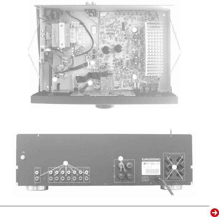
Ausbauhinweise
1.Öffnen des Gehäuses
-Die 4 Schrauben A (Fig. 1) und die 2 Schrauben B (Fig. 2) herausschrauben.
-Den Deckel abheben.
2.Ausbau der Frontplatte
-Schraube C(Fig. 3) herausschrauben.
-Die Rastung Dder Netztaste ausrasten (Fig. 1).
-Die 2 Füße E(Fig. 3) abschrauben.
-Die 3 Rastnasen F(Fig. 3) ausrasten.
-Beim Zusammenbau auf richtigen Sitz des Steckverbinders G (Fig. 1) achten.
3.Ausbau der Hauptplatte
-Frontplatte ausbauen (Pkt. 2).
-Die 5 Schrauben H (Fig. 1) und die 7 Schrauben J (Fig. 2) herausschrauben.
-Die Platte herausheben, dabei Steckverbinder nach Bedarf öffnen.
4.Ausbau der Trafoplatte
-Die Rastung Dder Netztaste ausrasten (Fig. 1).
-Die 4 Schrauben K (Fig. 2) und die 5 Schrauben L (Fig. 3) herausschrauben.
-Trafoplatte mit AC-Outlet-Platte herausheben, Steckverbinder nach Bedarf öffnen.
Disassembly Instructions
1.Opening the Cabinet
-Undo the 4 srews A (Fig. 1) and the 2 screws B (Fig. 2).
-Remove the top of the cabinet.
2.Removing the Front Panel
-Undo screw C(Fig. 3).
-Disengage the mains button D (Fig. 1).
-Undo 2 feet E(Fig. 3).
-Disengage the 3 catches F (Fig. 1).
-When mounting the board, look for the correct position of connector
G (Fig. 1).
3.Removing the Main Board
-Remove the Front Panel (para 2).
-Undo the 5 screws H (Fig. 1) and the 7 screws J(Fig. 2).
-The main board can now be removed. Open connectors if necessary.
4.Removing the Power Supply Board
-Disengage the mains button D (Fig. 1).
-Undo the 4 screws K (Fig. 2) and the 5 screws L(Fig. 3).
-Remove Power Supply Board together with the AC Outlet Board, open connectors if necessary
H
A A H
D H
G
Fig. 1
B B
J
J
K
Fig. 2
GRUNDIG Service |
1 - 3 |

Allgemeiner Teil / General Section |
V 21 |
5. Ausbau der Potiplatte (Fig. 4)
-Lautstärkeknopf abziehen.
-Die Mutter M losschrauben.
-Die Potiplatte kann jetzt nach innen herausgezogen werden. Bei
Bedarf die Kabel Nablöten.
5.Disassembling of the Potentiometer Board (Fig. 4)
-Pull off the volume knob.
-Disengage the nut M.
-The PCB can now be removed. If necessary unsolder the wires N.
L
E F E
C
Fig. 3
6.Zerlegen der Frontplatte (Fig. 5)
-Frontplatte ausbauen (Pkt. 2).
-Potiplatte ausbauen (Pkt. 5).
-Die 9 Schrauben O (Fig. 5) herausschrauben.
-Die Leiterplatte P kann jetzt abgenommen werden.
M
N
Fig. 4
6.Disassembling of the Front Panel (Fig. 5)
-Remove the Front Board (para 2).
-Remove the potentiometer board (para 5).
-Undo 9 screws O(Fig. 5).
-The PCB Pcan now be removed.
 O
O
 O
O
P
Fig. 5
7.Ausbau der Eingangswahltasten (Fig. 6)
-Frontplatte zerlegen (Pkt. 6).
-Rastnase Rausrasten und die Taste herausnehmen.
7.Disassemble the Input Selection Buttons (Fig. 6)
-Disassemble the front panel (para 6).
-Disengage the catch Rand pull out the button.
R
Fig. 6
1 - 4 |
GRUNDIG Service |
 Loading...