


 Loading...
|
HiFi |
|
|
|
|
|
|
|
|
|
|
|
|
|
|
|
|
|
|
|
|
|
Service Manual |
|
|||
|
U M S 4 1 0 1 S T E R E O M I C R O H I F I S Y S T E M |
+ V O L U M E – |
C D |
R E C O R D |
T U N E R / R A D I O |
TA P E / A U X |
TAPE MODE |
O N / O F F |
Zusätzlich erforderliche Unterlagen für den Komplettservice
Additionally required Service Documents for the Complete Service
Service
Manual
Sicherheit
Safety
Materialnr./Part No.
720108000000
Materialnummer/Part Number 720107718000
Änderungen vorbehalten/Subject to alteration • Printed in Germany • WÜ H-S44 • 0102 • 8002/8012, 8005/8015, 8006/8016 http://www.grundig.com
CIRFLEXX
UMS 4100
GLL0150
CIRFLEXX
UMS 4101
GLL0350
Grundig Service
|
Hotline Deutschland… |
|
…Mo.-Fr. 8.00-18.00 Uhr |
||
Technik: |
|
|
TV |
0180/52318-41 |
|
TV |
0180/52318-49 |
|
SAT |
0180/52318-48 |
|
VCR/LiveCam |
0180/52318-42 |
|
HiFi/Audio |
0180/52318-43 |
|
Car Audio |
0180/52318-44 |
|
Telekommunikation |
0180/52318-45 |
|
Fax: |
0180/52318-51 |
|
Planatron (8.00-22.00 Uhr) 0180/52318-99 |
||
Ersatzteil-Verkauf: |
Mo.-Fr. 8.00-19.00 Uhr |
|
Telefon: |
0180/52318-40 |
|
Fax: |
0180/52318-50 |
|
Kundendienst/Werkstätten: Mo.-Fr. 8.00-18.00 Uhr |
||
Telefon: |
0180/52318-52 |
|
Fax: |
0180/52318-46 |
|
gebührenpflichtig

Allgemeiner Teil / General Section |
UMS 4100, UMS 4101 |
Es gelten die Vorschriften und Sicherheitshinweise gemäß dem Service Manual "Sicherheit", Materialnummer 720108000000, sowie zusätzlich die eventuell abweichenden, landesspezifischen Vorschriften!
The regulations and safety instructions shall be valid as provided by the "Safety" Service Manual, part number 720108000000, as well as the respective national deviations!
Inhaltsverzeichnis
|
Seite |
Allgemeiner Teil ........................... |
1 - 2 … 1 - 11 |
Messgeräte / Messmittel ............................................................ |
1 - 2 |
Technische Daten ...................................................................... |
1 - 3 |
Servicehinweise ......................................................................... |
1 - 3 |
Ausbauhinweise ......................................................................... |
1 - 4 |
Bedienhinweise .......................................................................... |
1 - 8 |
Abgleichvorschriften ...................... |
2 - 1 ... 2 - 2 |
Platinenabbildungen |
|
und Schaltpläne ........................... |
3 - 1 … 3 - 23 |
Blockschaltplan .......................................................................... |
3 - 1 |
Verdrahtungsplan ....................................................................... |
3 - 2 |
Schaltpläne: |
|
Verstärkerteil .......................................................................... |
3 - 6 |
Rundfunkteil ........................................................................... |
3 - 8 |
CDund Prozessorteil .......................................................... |
3 - 14 |
Cassettenteil (nur UMS 4101) .............................................. |
3 - 16 |
Netzteil ................................................................................. |
3 - 19 |
Display-Platte ....................................................................... |
3 - 20 |
Bedien-Platten UMS 4100 .................................................... |
3 - 22 |
Bedien-Platten UMS 4101 .................................................... |
3 - 23 |
Platinenabbildungen: |
|
Verstärkerteil .......................................................................... |
3 - 4 |
Rundfunkteil ......................................................................... |
3 - 10 |
CDund Prozessorteil .......................................................... |
3 - 12 |
Cassettenteil (nur UMS 4101) .............................................. |
3 - 18 |
Netzteil ................................................................................. |
3 - 19 |
Display-Platte ....................................................................... |
3 - 21 |
Bedien-Platten UMS 4100 .................................................... |
3 - 22 |
Bedien-Platten UMS 4101 .................................................... |
3 - 23 |
Explosionszeichnungen und |
|
Ersatzteillisten ................................ |
4 - 1 … 4 - 8 |
Explosionszeichnung UMS 4100 ............................................... |
4 - 1 |
Ersatzteilliste UMS 4100 ............................................................ |
4 - 5 |
Explosionszeichnung UMS 4101 ............................................... |
4 - 3 |
Ersatzteilliste UMS 4101 ............................................................ |
4 - 7 |
Table of Contents
|
Page |
General Section ............................ |
1 - 2 … 1 - 15 |
Measuring Instruments / Equipment .......................................... |
1 - 2 |
Technical Data ........................................................................... |
1 - 3 |
Service Hints .............................................................................. |
1 - 3 |
Disassembly Instructions ........................................................... |
1 - 4 |
Operating Hints ........................................................................ |
1 - 12 |
Adjustment Procedures.................. |
2 - 3 ... 2 - 4 |
Layout of PCBs |
|
and Circuit Diagrams ................... |
3 - 1 … 3 - 23 |
Block Diagram ............................................................................ |
3 - 1 |
Wiring Diagram .......................................................................... |
3 - 2 |
Circuit Diagrams: |
|
Amplifier Part .......................................................................... |
3 - 6 |
Tuner Part .............................................................................. |
3 - 8 |
CD and Processor Part ........................................................ |
3 - 14 |
Cassette Part (only UMS 4101) ........................................... |
3 - 16 |
Mains Unit ............................................................................ |
3 - 19 |
Display PCB ......................................................................... |
3 - 20 |
Keyboards UMS 4100 .......................................................... |
3 - 22 |
Keyboards UMS 4101 .......................................................... |
3 - 23 |
Layout of the PCBs: |
|
Amplifier Part .......................................................................... |
3 - 4 |
Tuner Part ............................................................................ |
3 - 10 |
CD and Processor Part ........................................................ |
3 - 12 |
Cassette Part (only UMS 4101) ........................................... |
3 - 18 |
Mains Unit ............................................................................ |
3 - 19 |
Display PCB ......................................................................... |
3 - 21 |
Keyboards UMS 4100 .......................................................... |
3 - 22 |
Keyboards UMS 4101 .......................................................... |
3 - 23 |
Exploded Views and |
|
Spare Parts Lists ............................ |
4 - 1 … 4 - 8 |
Exploded View UMS 4100 ......................................................... |
4 - 1 |
Spare Parts List UMS 4100 ....................................................... |
4 - 5 |
Exploded View UMS 4101 ......................................................... |
4 - 3 |
Spare Parts List UMS 4101 ....................................................... |
4 - 7 |
Allgemeiner Teil |
General Section |
Messgeräte / Messmittel
Frequenzzähler |
Mess-Sender |
Wobbelsender |
Oszilloskop |
Digitalvoltmeter |
Klirrfaktormessgerät |
Testcassette 3150Hz/10kHz (z.B. 448)
Beachten Sie bitte das GRUNDIG Messtechnik-Programm, das Sie unter folgender Adresse erhalten:
Measuring Instruments / Equipment
Frequency counter |
Signal generator |
Sweep generator |
Oscilloscope |
Digital voltmeter |
Distortion meter |
Test cassette 3150Hz/10kHz (e.g. 448)
Please note the GRUNDIG Catalog "Test and Measuring Equipment" obtainable from:
GRUNDIG AG Geschäftsbereich Instruments Testund Mess-Systeme
Würzburger Str. 150
D 90766 Fürth/Bay
Tel. 0911/703-4540
Fax 0911/703-4130
eMail: instruments@grundig.com Internet: http://www.grundig-instruments.de
1 - 2 |
GRUNDIG Service |

UMS 4100, UMS 4101 |
Allgemeiner Teil / General Section |
Technische Daten
Verstärkerteil |
|
|
|
Ausgangsleistung: |
|
|
|
Sinusleistung ........................................................................ |
|
|
2 x 12W |
Musikleistung ....................................................................... |
|
|
2 x 20W |
Eingangsempfindlichkeit/Impedanz |
............................. 500mV/22kΩ |
||
Empfangsteil |
|
|
|
Empfangsbereich FM ............................................. |
|
87,5 ... |
108,0MHz |
Empfangsbereich MW .............................................. |
|
522 ... |
1620kHz |
CD Teil |
|
|
|
Frequenzgang ............................................................ |
|
20Hz ... 20kHz |
|
Geräuschspannungsabstand (wtd.) |
........................................ |
>90dB |
|
Cassettenteil (nur UMS 4101) |
|
|
|
Tonträger ....................... |
Compact-Cassette nach DIN 45516 (IECI) |
||
Frequenzbereich ..................................................... |
... |
40Hz |
14,0kHz |
Spurlage ....................................................... |
|
Viertelspur international |
|
Geräuschspannungsabstand (wtd.) .......................................... |
|
55dB |
|
Gleichlaufschwankungen (WRMS) ....................................... |
|
±0,15% |
|
Spannungsversorgung |
|
|
|
Betriebsspannung ................................................................... |
|
|
230V~ |
Netzfrequenz ........................................................................ |
|
|
50/60Hz |
max. Leistungsaufnahme ........................................................... |
|
|
75W |
Leistungsaufnahme in Standby .................................................. |
|
<2W |
|
Abmessungen und Gewicht |
|
|
|
Abmessungen UMS4101 ................... |
|
B x H x T 170 x 245 x 230mm |
|
Gewicht UMS4101 .................................................................... |
|
|
3,9kg |
Abmessungen UMS4100 ................... |
|
B x H x T 175 x 245 x 230mm |
|
Gewicht UMS4100 .................................................................... |
|
|
3,1kg |
Abmessungen Lautsprecher .............. |
B x H x T 130 x 240 x 160mm |
||
Gewicht pro Lautsprecher ......................................................... |
|
1,3kg |
|
Technical Data
Amplifier unit |
|
|
Output: |
|
|
Sinusoidal power .................................................................. |
|
2 x 12W |
Music signal power .............................................................. |
|
2 x 20W |
Input sensitivity/impedance .......................................... |
500mV/22kΩ |
|
Receiver unit |
|
|
Reception range FM ............................................. |
87.5 ... |
108.0MHz |
Reception range MW ............................................... |
522 ... |
1620kHz |
CD unit |
|
|
Frequency response .................................................. |
20Hz ... 20kHz |
|
Noise voltage ratio ........................................................ |
(wtd.) >90dB |
|
Cassette unit (UMS 4101 only) |
|
|
Sound recording medium ............................................ |
Compact tape |
|
|
according to DIN 45516 (IECI) |
|
Frequency range ..................................................... |
40Hz ... |
14.0kHz |
Tracking position ...................................... |
International quarter-track |
|
Noise voltage ratio (wtd.) .......................................................... |
|
55dB |
Wow and flutter (WRMS) ...................................................... |
|
±0.15% |
Power supply |
|
|
Operating voltage .................................................................... |
|
230V~ |
Mains frequency ................................................................... |
|
50/60Hz |
Max. power consumption ........................................................... |
|
75W |
Power consumption in stand-by mode ....................................... |
<2W |
|
Dimensions and weight |
|
|
Dimensions of UMS4101 .................. |
W x H x L 170 x 245 x 230mm |
|
Weight of UMS4101 .................................................................. |
|
3.9kg |
Dimensions of UMS4100 .................. |
W x H x L 175 x 245 x 230mm |
|
Weight of UMS4100 .................................................................. |
|
3.1kg |
Dimensions of speakers .................... |
W x H x L 130 x 240 x 160mm |
|
Weight per speaker ................................................................... |
|
1.3kg |
Servicehinweise
Vor Öffnen des Gehäuses Netzstecker ziehen.
Cassettenteil
Überprüfen Sie vor Beginn der Service-Arbeiten, ob die Magnetköpfe, die Tonwelle und die Gummiandruckrolle frei von Bandabrieb sind.
Zum Reinigen dieser Teile verwenden Sie ein mit Spiritus oder Reinigungsbenzin getränktes Wattestäbchen; dadurch verbessert sich der Aufnahmeund Wiedergabepegel, sowie der Bandlauf.
Nach dem Ersatz von Magnetköpfen oder sonstiger Bauteile müssen die technischen Daten des Gerätes anhand der im Service Manual vorgegebenen Messwerte überprüft bzw. eingestellt werden.
Leitungsverlegung
Bevor Sie die Leitungen und insbesondere die Masseleitungen lösen, muss die Leitungsverlegung zu den einzelnen Baugruppen beachtet werden.
Nach erfolgter Reparatur ist es notwendig, die Leitungsführung wieder in den werkseitigen Zustand zu versetzen um evtl. spätere Ausfälle oder Störungen zu vermeiden.
Service Hints
Disconnect the mains plug before opening the set.
Cassette Section
Before commencing service work, ensure that the magnetic heads, the capstan and the pinch roller are free from particles produced by tape abrasion. The recording and playback levels and the tape run can be improved by cleaning these parts with a cotton-wool tip soaked in spirit or cleaning benzine.
If the heads or other components have been replaced, the technical data of the recorder must be checked or adjusted according to the values specified in the Service Manual.
Wiring
Before disconnecting any leads and especially the earth connecting leads observe the way they are routed to the individual assemblies. On completion of the repairs the leads must be laid out as originally fitted at the factory to avoid later failures or disturbances.
GRUNDIG Service |
1 - 3 |
Allgemeiner Teil / General Section |
UMS 4100, UMS 4101 |
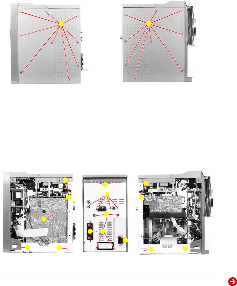
Ausbauhinweise
Bevor Sie Leitungen lösen, muss die Leitungsverlegung beachtet werden. Nach erfolgter Reparatur ist es notwendig, die Leitungsführung in den werkseitigen Zustand zu versetzen.
1.Gehäuseseitenteile
-18 Schrauben A (Fig. 1, 2) herausdrehen.
-Gehäuseseitenteile nach hinten schieben und abnehmen.
Disassembly Instructions
Before disconnecting any leads observe the way they are routed. On completion of the repairs the leads must be laid out as originally fitted at the factory.
1.Cabinet Sides
-Undo 18 screws B (Fig. 1, 2).
-Move the sides to the rear and remove.
A |
A |
Fig. 1
2.Gehäuserückwand
-Gehäuseseitenteile abnehmen (Punkt 1).
-7 Schrauben B (Fig. 4) herausdrehen.
-2 Schrauben C (Fig. 4) herausdrehen.
-6 Schrauben D (Fig. 3, 4, 5) herausdrehen.
-2 Schrauben E (Fig. 4) herausdrehen.
-2 Masseleitungen F (Fig. 3, 5) abziehen.
-Gehäuseoberteil mit Cassettenteil hinten anheben, 2 Rastnasen G
(Fig. 4) ausrasten und Gehäuserückwand abnehmen.
3.Gehäuseoberteil mit Cassettenteil
-Gehäuserückwand abnehmen (Punkt 2).
-Gehäuseoberteil mit Cassettenteil hinten anheben, an der Frontblende aushängen und abnehmen.
-Bei Bedarf Steckverbindungen lösen.
Fig. 2
2.Cabinet Rear
-Remove the Sides (point 1).
-Undo 7 screws B (Fig. 4).
-Undo 2 screws C (Fig. 4).
-Undo 6 screws D (Fig. 3, 4, 5).
-Undo 2 screws E (Fig. 4).
-Unplug 2 ground connectors F (Fig. 3, 5).
-Lift the Cabinet top together with the Cassette Part at the rear, disengage hooks G (Fig. 4) and remove the cabinet rear.
3.Cabinet Top together with the Cassette Part
-Remove the cabinet rear (point 2).
-Lift the Cabinet top together with the Cassette Part at the rear, disengage at the front and remove.
-When necessary unplug the connections.
F |
f
V |
W D
Fig. 3
C |
B |
G |
B |
D |
Fig. 4
F |
f
E |
D W
Fig. 5
1 - 4 |
GRUNDIG Service |
UMS 4100, UMS 4101 |
Allgemeiner Teil / General Section |
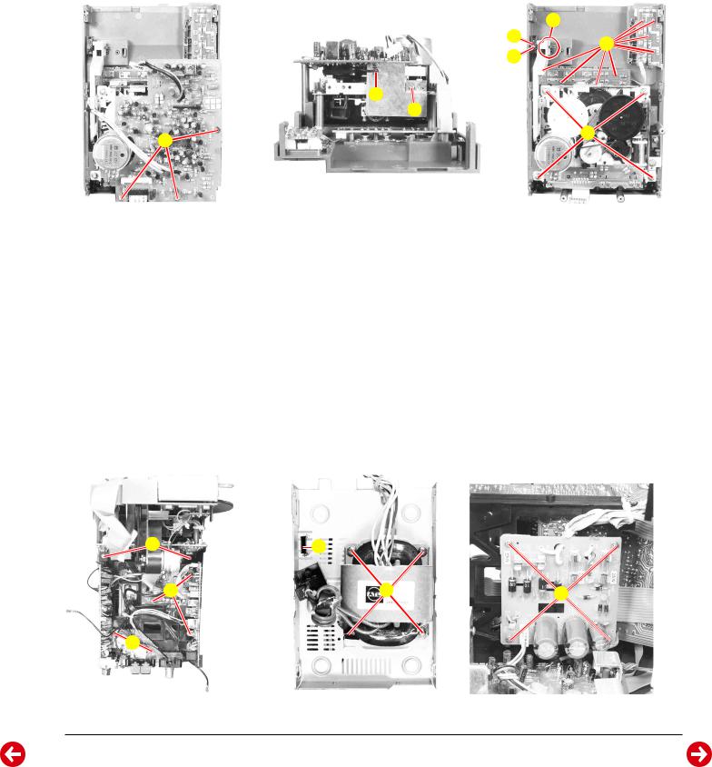
4.Leiterplatte Cassettenteil
-Gehäuseoberteil mit Cassettenteil abnehmen (Punkt 3).
-3 Schrauben H (Fig. 6) herausdrehen.
-Schraube I (Fig. 7) herausdrehen.
-Masseleitung J (Fig. 7) bei Bedarf ablöten.
-Bei Bedarf Steckverbindungen lösen.
5.Cassettenlaufwerk
-Leiterplatte Cassettenteil abnehmen (Punkt 4).
-Schraube K(Fig. 8) herausdrehen und Führung L (Fig. 8) abnehmen.
-4 Schrauben M (Fig. 8) herausdrehen.
-Schieber N (Fig. 8) aushängen.
6.Bedienplatten Gehäuseoberteil
-Gehäuseoberteil mit Cassettenteil abnehmen (Punkt 3).
-9 Schrauben O (Fig. 8) herausdrehen.
4.Cassette PCB
-Remove the cabinet top together with the cassette part (point 3).
-Undo 3 screws H (Fig. 6).
-Undo screw I (Fig. 7).
-When necessary unsolder ground connection J (Fig. 7).
-When necessary unplug the connections.
5.Cassette Mechanism
-Remove the Cassette PCB (point 4).
-Undo screw K (Fig. 8) and remove guide L (Fig. 8).
-Undo 4 screws M (Fig. 8).
-Unhook slider N (Fig. 8).
6.Operating PCBs of Cabinet Top
-Remove the cabinet top together with the cassette part (point 3).
-Undo 9 screws O (Fig. 8).
J |
I |
H |
N |
L |
O |
|
K |
||
|
M |
Fig. 6 |
Fig. 7 |
7.Leiterplatte FM-Tuner/Antennen-Buchsen
-Gehäuseoberteil mit Cassettenteil abnehmen (Punkt 3).
-2 Schrauben P (Fig. 9) herausdrehen.
-Bei Bedarf Steckverbindungen lösen.
8.Leiterplatten AM/ZF und PLL
-Gehäuseoberteil mit Cassettenteil abnehmen (Punkt 3).
-3 Schrauben Q (Fig. 9) herausdrehen.
-Bei Bedarf Steckverbindungen lösen.
9.Montagerahmen mit Leiterplatten
-Gehäuseoberteil mit Cassettenteil abnehmen (Punkt 3).
-2 Schrauben R (Fig. 9) herausdrehen.
-Bei Bedarf Steckverbindungen lösen.
-Beim Einbau darauf achten, dass die Hauptplatte in die Führung S (Fig. 10) eingreift.
Fig. 8
7.FM Tuner/Antenna Sockets PCB
-Remove the cabinet top together with the cassette part (point 3).
-Undo 2 screws P (Fig. 9).
-When necessary unplug the connections.
8.AM/IF and PLL PCBs
-Remove the cabinet top together with the cassette part (point 3).
-Undo 3 screws Q (Fig. 9).
-When necessary unplug the connections.
9.Mounting Frame with PCBs
-Remove the cabinet top together with the cassette part (point 3).
-Undo 2 screws R (Fig. 9).
-When necessary unplug the connections.
-When reassembling take care, that the main PCB engages with its guide S (Fig. 10).
R |
Q |
P
Fig. 9
S
U T
Fig. 10 |
Fig. 11 |
GRUNDIG Service |
1 - 5 |
Allgemeiner Teil / General Section |
UMS 4100, UMS 4101 |
10.Leiterplatte Netzteil
-Montagerahmen lösen (Punkt 9).
-4 Schrauben T (Fig. 11) herausdrehen.
-Bei Bedarf Steckverbindungen lösen.
11.Transformator
-Montagerahmen lösen (Punkt 9).
-4 Schrauben U (Fig. 10) herausdrehen.
-Bei Bedarf Leitungen zur Netzteilplatte ablöten.
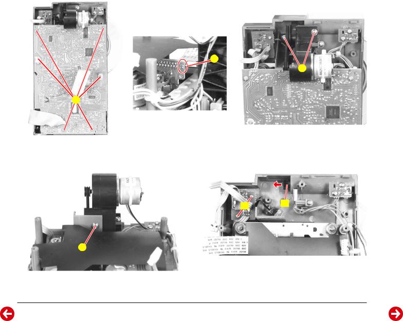
12.Verstärkerplatte
-Montagerahmen lösen (Punkt 9).
-2 Schrauben V (Fig. 3) herausdrehen.
-Bei Bedarf Steckverbindungen lösen.
13.Front mit CD-Teil
-Montagerahmen lösen (Punkt 9).
-2 Rastungen W (Fig. 3, 5) lösen.
-Bei Bedarf Steckverbindungen lösen.
14.CD-Leiterplatte
-Front mit CD-Teil abnehmen (Punkt 13).
-6 Schrauben X (Fig. 12) herausdrehen.
-Vor abziehen des Flexprints zum CD-Laufwerk Sicherheitslötstelle Y (Fig. 13) schließen.
-Bei Bedarf Steckverbindungen lösen.
15.Antrieb CD-Tür
-CD-Leiterplatte ausbauen (Punkt 14).
-3 Schrauben Z (Fig. 14, 15) herausdrehen.
-Antrieb aushängen und abnehmen.
-CD-Tür-Achse A (Fig. 16) in Pfeilrichtung abziehen.
10.Mains Unit PCB
-Loosen the mounting frame (point 9).
-Undo 4 screws T (Fig. 11).
-When necessary unplug the connections.
11.Transformer
-Loosen the mounting frame (point 9).
-Undo 4 screws U (Fig. 10).
-When necessary unsolder the wires to the mains unit.
12.Amplifier PCB
-Loosen the mounting frame (point 9).
-Undo 2 screws V (Fig. 3).
-When necessary unplug the connections.
13.Front together with the CD Part
-Loosen the mounting frame (point 9).
-Disengage 2 hooks W (Fig. 3, 5).
-When necessary unplug the connections.
14.CD PCB
-Remove the front together with the CD part (point 13).
-Undo 6 screws X (Fig. 12).
-Short circuit the safety solder pads Y(Fig. 13) before disconnecting the flexprint to the CD mechanism.
-When necessary unplug the connections.
15.CD Door Drive
-Remove the CD PCB (point 14).
-Undo 3 screws Z (Fig. 14, 15).
-Unhook the drive and remove.
-Pull out the CD door axle A (Fig. 16) in direction of the arrow.
Y |
Z |
X |
Fig. 12 |
Fig. 13 |
Fig. 14 |
E A
Z |
Fig. 15 |
Fig. 16 |
1 - 6 |
GRUNDIG Service |
UMS 4100, UMS 4101 |
Allgemeiner Teil / General Section |
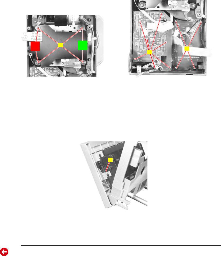
16.CD-Laufwerk
-CD-Leiterplatte ausbauen (Punkt 14).
-4 Schrauben B (Fig. 17) herausdrehen.
-Bei Bedarf Steckverbindungen lösen.
-Beim Einbau die Farbe der Gummidämpfer beachten!
17.Bedienplatte Frontseite
-CD-Leiterplatte ausbauen (Punkt 14).
-7 Schrauben C (Fig. 18) herausdrehen.
18.Displayplatte
-CD-Leiterplatte ausbauen (Punkt 14).
-4 Schrauben D (Fig. 18) herausdrehen.
rot |
B |
grün |
|
green |
|||
red |
|
Fig. 17
19.IR-Empfänger-Leiterplatte
-Gehäuseoberteil mit Cassettenteil abnehmen (Punkt 3).
-2 Schrauben E (Fig. 16) herausdrehen.
20.Cassettenfachblende
Für den Azimut-Abgleich des Cassettenlaufwerks muss die Cassettenfachblende abgenommen werden.
-2 Rastungen F (Fig. 19) ausrasten.
-Cassettenfachblende nach oben abziehen.
16.CD Mechanism
-Remove the CD PCB (point 14).
-Undo 4 screws B (Fig. 17).
-When necessary unplug the connections.
-When reassembling pay attention to the different colors of the damper!
17.Operating PCB Front
-Remove the CD PCB (point 14).
-Undo 7 screws C (Fig. 18).
18.Displayplatte
-Remove the CD PCB (point 14).
-Undo 4 screws D (Fig. 18).
D
C
Fig. 18
19.IR Receiver PCB
-Remove the cabinet top together with the cassette part (point 3).
-Undo 2 screws E (Fig. 16).
20.Cassette Compartment Cover
Do do the azimuth adjustment of the cassette mechanism the cassette compartment cover must be removed.
-Disengage 2 hooks F (Fig. 19).
-Pull up the cassette compartment cover to the top.
F
Fig. 19
GRUNDIG Service |
1 - 7 |
Allgemeiner Teil / General Section |
UMS 4100, UMS 4101 |
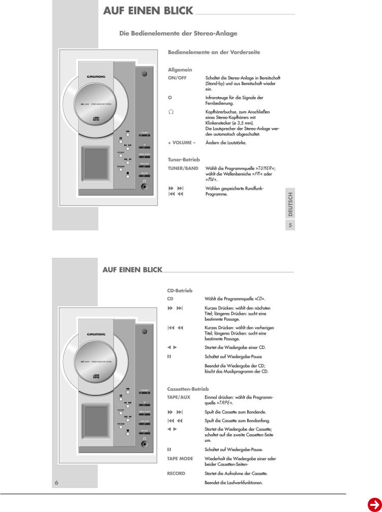
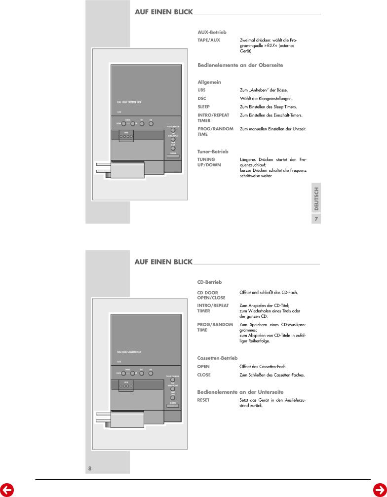
Bedienhinweise
Dieses Kapitel enthält Auszüge aus der Bedienungsanleitung. Weitergehende Informationen entnehmen Sie bitte der gerätespezifischen Bedienungsanleitung, deren Materialnummer Sie in der entsprechenden Ersatzteilliste finden.
1 - 8 |
GRUNDIG Service |
UMS 4100, UMS 4101 |
Allgemeiner Teil / General Section |
GRUNDIG Service |
1 - 9 |

Allgemeiner Teil / General Section |
UMS 4100, UMS 4101 |
1 - 10 |
GRUNDIG Service |
UMS 4100, UMS 4101 |
Allgemeiner Teil / General Section |
GRUNDIG Service |
1 - 11 |
Allgemeiner Teil / General Section |
UMS 4100, UMS 4101 |
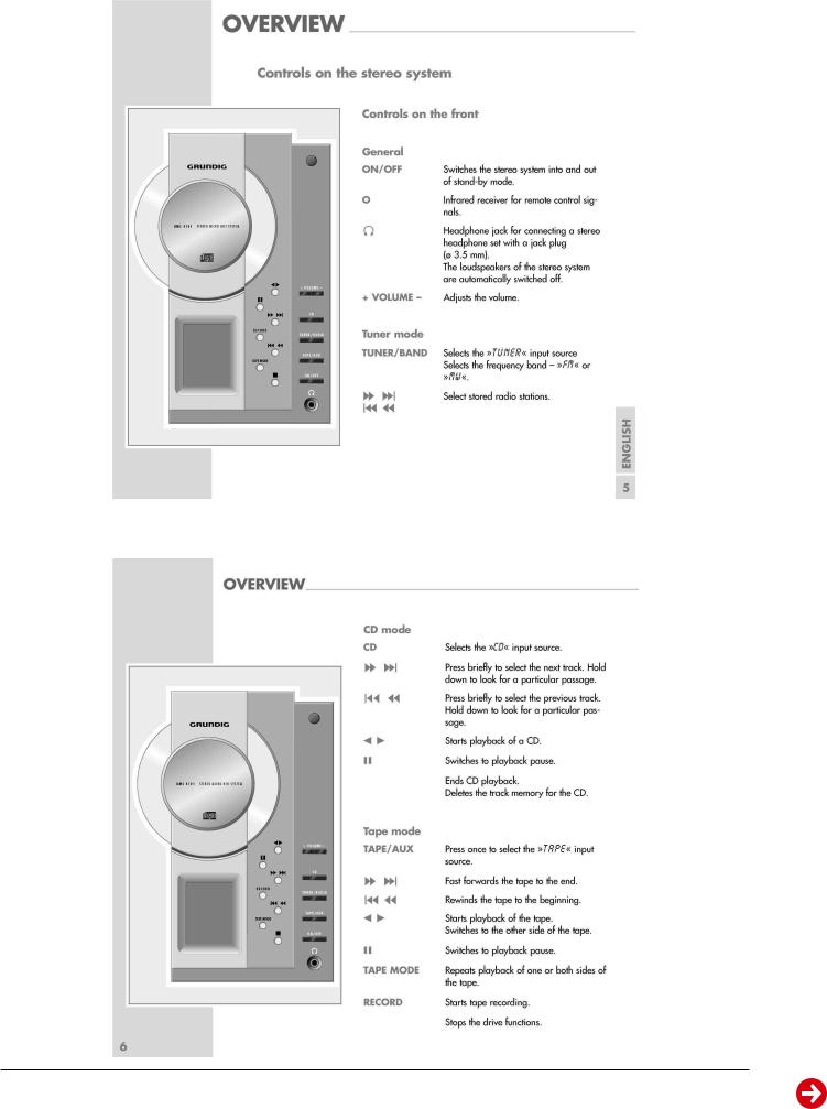
Operating Hints
This chapter contains excerpts from the operating instructions. For further particulars please refer to the appropriate user instructions the part number of which is indicated in the relevant spare parts list.
1 - 12 |
GRUNDIG Service |
Loading...