


|
Document 464652 |
|
Model Vektor®-MH, Vektor®-MD |
® |
and Vektor®-MS |
|
Laboratory Exhaust System |
Installation, Operation and Maintenance Manual
Please read and save these instructions for future reference. Read carefully before attempting to assemble, install, operate or maintain the product described. Protect yourself and others by observing all safety information. Failure to comply with instructions could result in personal injury and/or property damage!
Vektor-MH, Vektor-MD, and Vektor-MS
Table of Contents
General Safety Information . . . . . . . . . . . . . . . . . . . . . .1 Receiving / Unpacking / Handling / Storage . . . . . 2-3
General Information
Unit and System Identification. . . . . . . . . . . . . . . . . .3 Pre-Installation Information . . . . . . . . . . . . . . . . . . . .3 Electrical Disconnects / Moving Parts / Guards . . . .3 Air Pressure and Suction . . . . . . . . . . . . . . . . . . . . . .3 System Components. . . . . . . . . . . . . . . . . . . . . . . . . 4-5 Roof Curb and Mounting Details . . . . . . . . . . . . . . . . .5
Bypass Air Plenum
Rigging, Lifting and Installation . . . . . . . . . . . . . . . 6-7 Fan Housing
Rigging, Lifting and Installation . . . . . . . . . . . . . . . 6-7 Nozzle, Windband, Silencer, Weatherhood . . . . . . . .8 Duct Connections - Side Inlet . . . . . . . . . . . . . . . . . . .9 Bottom Inlet . . . . . . . . . . . . . . . . .9 Plenum Drainage Piping / Trap Detail . . . . . . . . . . . . . .9
Bypass Air Plenum - Isolation Damper and
Actuator Mounting . . . . . . . . . . . . . . . . . . . . . . . . . .10 Field Coating Touch-Up . . . . . . . . . . . . . . . . . . . . . . .10 Electrical Connections . . . . . . . . . . . . . . . . . . . . . . . .11 Start-Up. . . . . . . . . . . . . . . . . . . . . . . . . . . . . . . . . . . .12 Vibration . . . . . . . . . . . . . . . . . . . . . . . . . . . . . . . . . . .13 Routine Maintenance
Fan / V-Belt Drive / Motors / Bearings / Nozzle 14-15 V-Belt Drive Installation . . . . . . . . . . . . . . . . . . . . . . . .15 Bearing Replacement - Belt or Direct Drive . . . . . 16-17 Jib Crane Assembly (Optional) . . . . . . . . . . . . . . . . . .17 Motor Change-Out Procedure . . . . . . . . . . . . . . . . . .18 High Strength Metal Disc Coupling. . . . . . . . . . . . . . .18 Troubleshooting. . . . . . . . . . . . . . . . . . . . . . . . . . . . . .19 Nozzle Parts and Assembly . . . . . . . . . . . . . Backcover Our Commitment. . . . . . . . . . . . . . . . . . . . . . Backcover
®
General Safety Information
Only qualified personnel should install this fan system. Personnel should have a clear understanding of these instructions and should be aware of general safety precautions. Improper installation can result in electric shock, possible injury due to coming in contact with moving parts, as well as other potential hazards. Other considerations may be required if high winds or seismic activity are present. If more information is needed, contact a licensed professional engineer before moving forward.
1.Follow all local electrical and safety codes, as well as the National Electrical Code (NEC), the National Fire Protection Agency (NFPA), where applicable. Follow the Canadian Electrical Code (CEC) in Canada.
2.The rotation of the wheel is critical. It must be free to rotate without striking or rubbing any stationary objects.
3.Motor must be securely and adequately grounded.
4.Do not spin fan wheel faster than maximum cataloged fan rpm. Adjustments to fan speed significantly effects motor load. If the fan RPM is changed, the motor current should be checked to make sure it is not exceeding the motor nameplate amps.
5.Do not allow the power cable to kink or come in contact with oil, grease, hot surfaces or chemicals. Replace cord immediately if damaged.
6.Verify that the power source is compatible with the equipment.
7.Never open access doors to a duct while the fan is running.
DANGER
Always disconnect power before working on or near a fan. Lock and tag the disconnect switch or breaker to prevent accidental power up.
CAUTION
When servicing the fan, motor may be hot enough to cause pain or injury. Allow motor to cool before servicing.
CAUTION
Precaution should be taken in explosive atmospheres.
Laboratory Exhaust Systems 1

Receiving
Greenheck model Vektor-MH, Vektor-MD and Vektor-MS fans are thoroughly inspected, test run at the factory, and shipped on a skid or packaged to minimize damage during shipment. The transportation carrier has the responsibility of delivering all items in their original condition as received from Greenheck. The individual receiving the equipment is responsible for inspecting the unit for obvious or hidden damage and recording any damage on the bill of lading before acceptance of the equipment. All claims (if necessary) shall be filed with the final carrier.
Unpacking
Verify that all required parts and the correct quantity of each item have been received, including accessory kit containing gasketing, etc. If any items are missing,
report shortages to your local representative to arrange for obtaining missing parts. Sometimes it is not possible that all items for the unit be shipped together due to availability of transportation and truck space. Confirmation of shipment(s) must be limited to only items on the bill of lading.
Handling
The Vektor-MH, Vektor-MD and Vektor-MS laboratory exhaust system is shipped in subassembly sections for easy rigging and installation. Depending on the fan size, the sections can include: Blower Assembly, Stack Extension, and Discharge Nozzle.
The Vektor-MH, Vektor-MD and Vektor-MS are designed to be self-supporting and standing (without the use
of guy wires) when assembled per the instructions provided within this manual. If additional components are supplied, contact factory or reference submittal
if additional supports or guy wires are required. All subassembly sections have lifting lugs as shown.
Storage
Fans are protected against damage during shipment. If the unit cannot be installed and operated immediately, precautions need to be taken to prevent deterioration of the unit during storage. The user assumes responsibility of the fan and accessories while in storage. The manufacturer will not be responsible for damage during storage. These suggestions are provided solely as a convenience to the user.
INDOOR - The ideal environment for the storage of fans and accessories is indoors, above grade, in a low humidity atmosphere which is sealed to prevent the entry of blowing dust, rain, or snow. Temperatures should be evenly maintained between 30° and 110°F. (-1°C and 43°C). Wide temperature swings may cause condensation and “sweating” of metal parts. All accessories must be stored indoors in a clean, dry atmosphere.
Remove any accumulations of dirt, water, ice or snow and wipe dry before moving to indoor storage. To avoid “sweating” of metal parts allow cold parts to reach room temperature. To dry parts and packages use a portable electric heater to get rid of any moisture build up. Leave coverings loose to permit air circulation and to allow for periodic inspection.
The unit should be stored at least 3½ in. (89 mm) off the floor on wooden blocks covered with moisture proof paper or polyethylene sheathing. Aisles between parts and along all walls should be provided to permit air circulation and space for inspection.
OUTDOOR - Fans designed for outdoor applications may be stored outdoors, if absolutely necessary. Roads or aisles for portable cranes and hauling equipment are needed.
The fan should be placed on a level surface to prevent water from leaking into the fan. The fan should be elevated on an adequate number of wooden blocks so that it is above water and snow levels and has enough blocking to prevent it from settling into soft ground. Locate parts far enough apart to permit air circulation, sunlight, and space for periodic inspection. To minimize water accumulation, place all fan parts on blocking supports so that rain water will run off.
Do not cover parts with plastic film or tarps as these cause condensation of moisture from the air passing through heating and cooling cycles.
Fan wheels should be blocked to prevent spinning caused by strong winds.
Inspection and Maintenance during Storage
While in storage, inspect fans once per month. Keep a record of inspection and maintenance performed; see backcover.
If moisture or dirt accumulations are found on parts, the source should be located and eliminated. At each inspection, rotate the wheel by hand ten to fifteen revolutions to distribute lubricant on motor and bearings. Bearings should be lubricated at three month intervavls. The quantity of grease should be per the lubrication label.
If paint deterioration begins, consideration should be given to touch-up or repainting. Fans with special
coatings may require special techniques for touch-up or repair.
Machined parts coated with rust preventive coating should be restored to good condition promptly if signs of rust occur. Immediately remove the original rust preventive coating with petroleum solvent and clean with lint-free cloths. Polish any remaining rust from surface with crocus cloth or fine emery paper and oil. Do not destroy the continuity of the surfaces. Wipe clean thoroughly with Tectyl® 506 (Ashland Inc.) or the equivalent. For hard to reach internal surfaces or for occasional use, consider using Tectyl® 511M Rust Preventive or WD-40® or the equivalent.
2 Laboratory Exhaust Systems
®
REMOVING FROM STORAGE
As fans are removed from storage to be installed in their final location, they should be protected and maintained in a similar fashion, until the fan equipment goes into operation.
Prior to assembly and installation of the Vektor fan and system components, inspect the fan assembly to make sure it is in working order.
1.Check all fasteners, set screws on the fan, wheel, bearings, drive, motor base and accessories for tightness.
2.Rotate the fan wheel(s) by hand and assure no parts are rubbing. Access to the wheel is obtained through a bolted panel located on the side of the fan housing.
3.Ensure proper wheel settings for radial gap and alignment (see page 18).
General Information
To ensure a successful installation, the instructions in this manual should be read and adhered to. Failure to comply with proper installation procedures may void the warranty.
Unit and System Identification Tags
Each fan has a permanently affixed manufacturer’s engraved metal nameplate containing the model number and individual serial number.
The tag shown is 
 an example of an


 identification nameplate


 on the fan. The


 information provides
 general details about
 the fan, as well as containing specific information unique to the unit. When contacting your Greenheck representative with future needs or questions, please have the information on this label available. Tags are mounted in an area which is clearly visible, usually on the side of the fan cabinet.
Vektor fan systems may arrive in component pieces due to shipping restrictions. Individual components of a system have matching identification tags which should be used to identify and assemble the complete system. Assembling systems with different identification tags can cause reductions in the fan(s) performance.
Prior to fully assembling and installing the VektorMH, Vektor-MD or Vektor-MS fans, inspect bypass air
plenums and the fan assembly to make sure they are in working order.
Pre-Installation Information
Before installation, it is important to be certain the mounting surface will bear the operating weight of the unit. For proper unit operation, it is also important that it be operated in a completely level position.
For further details on safety practices involving industrial and commercial fans, please refer to AMCA Publication 410.
®
Electrical Disconnects
All fan motors should have disconnects located in close visual proximity to turn off electrical service. Service disconnects shall be locked-out when maintenance is being performed.
Moving Parts
All moving parts must have guards to protect personnel. Refer to local codes for requirements as to the number, type and design. Fully secure fan wheel before performing any maintenance. The fan wheel may start “free wheeling” even if all electrical power has been disconnected. Before the initial start-up or any restart, check the following items to make sure that they are installed and secure.
•Do not spin fan wheel faster than the maximum cataloged fan rpm.
•Adjustments to fan speed significantly affects motor load. If the fan RPM is changed, the motor current should be checked to make sure it is not exceeding the motor nameplate amps.
Guards (Motor Cover, Weatherhoods,
Actuator Cover)
Do not operate fans without proper protective devices in place. Failure to do so may result in serious bodily injury and property damage. Check local codes to ensure compliance for all protective devices.
Plenum Access Doors
Before opening access doors, ensure the fan wheel has stopped moving and that the wheel has been secured from being able to rotate. Do not operate fan without access door in its fully closed position.
Air Pressure and Suction
In addition to the usual hazards associated with rotating machinery, fans also create a dangerous suction at the inlet. Special caution needs to be used when moving around a fan, whether it is in operation or not. Before start-up, make sure the inlet area is clear of personnel and loose objects.
Laboratory Exhaust Systems 3
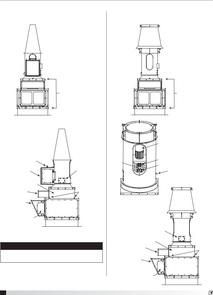
System Components
Vektor-MH Assembly View - Belt Drive
Belt and direct drive units share similar system components and assembly configuration.
 Nozzle
 Blower Housing
Bypass Air Plenum
 Roof Curb or
Structural Support
Motor Cover
Lifting Lug
Motor Cover/Access |
Blower Housing |
|
Access Door |
Isolation Damper |
|
Isolation Damper |
Panel Lifting |
Actuator Cover |
Lugs |
Weatherhood |
Access Panel |
with Birdscreen |
|
|
Bolted / Gasketed |
|
(all sides) |
Bypass Damper |
|
Actuator Access Door |
|
NOTE
Actual component pieces may vary from these images. Refer to your project submittal drawing.
Vektor-MD Assembly View - Direct Drive
Belt and direct drive units share similar system components and assembly configuration.
 Windband
 Nozzle
 Blower Housing
Bypass Air Plenum
 Roof Curb or
Structural Support
|
Motor |
Fan |
Flex Coupling |
Shaft |
Shaft Bearing |
|
|
|
Drain |
Direct Drive
Blower Housing |
Access Door |
Isolation Damper |
Isolation Damper |
Panel |
Actuator Cover |
Lifting |
|
Lugs |
Weatherhood |
|
with Birdscreen |
Access Panel |
|
Bolted / Gasketed |
|
(all sides) |
Bypass Damper |
|
Actuator Access Door |
|
4 Laboratory Exhaust Systems
®

Vektor-MS Assembly View - Direct Drive
Belt and direct drive units share similar system components and assembly configuration.
 SAVVE Nozzle
 Blower Housing
Bypass Air Plenum
 Roof Curb or
Structural Support
Blower Housing
Access Door
Isolation Damper |
|
|
Isolation Damper |
Panel |
|
Actuator Cover |
Lifting |
|
|
Lugs |
|
Weatherhood |
Access Panel |
|
with Birdscreen |
||
Bolted / Gasketed |
||
|
||
|
(all sides) |
|
Bypass Damper |
|
|
Actuator Access Door |
|
Roof Curb and Mounting Details
®
NOTE
Steel, concrete or wood roof support is per structural engineer and in accordance with load requirements and applicable building codes.
Refer to stand-alone Vektor Roof Curb Assembly Instruction found on greenheck.com within the Laboratory Exhaust section. Chose applicable product model.
The figures illustrates three common methods used to install Vektor systems. Methods used to attach a Vektor unit are dependent on local codes, roof construction design and roof construction materials. Consult an architect or structural engineer for proper means of attachment.
Steel
Greenheck Roof Curb
Continuous weld or stitch weld. Minimum 6 inch (152.4 mm) stitch weld by 3.25 inch (82.5 mm) spacing minimum.
Minimum 6 inch (152.4 mm) weld on each corner. OR
Install 5/16 inch (7.9375 mm) 24 Dril-Flex® Self-Drilling Tapping Screws. 3/16 inch (4.7625 mm) minimum thread
engagement into A36 steel, centered in flange. 
 4.5 inch (114.3 mm) spacing

 5/8 inch (15.875 mm) minimum edge distance
ALL HARDWARE BY OTHERS
STEEL STRUCTURAL SUPPORT (BY OTHERS, SEE NOTE ABOVE)
Concrete
Greenheck Roof Curb
Install 3/8 inch (9.525 mm) SS power wedge bolts
2.5 inch (63.5 mm) maximum spacing from curb corners
4.5 inch (114.3 mm) maximum bolt spacing
3.5 inch (88.9 mm) minimum embedment
4.5 inch (114.3 mm) minimum edge distance centered in flange
ALL HARDWARE BY OTHERS
|
CONCRETE STRUCTURAL SUPPORT |
|
(BY OTHERS, SEE NOTE ABOVE) |
Wood |
Greenheck Roof Curb |
Install 3/8 inch (9.525 mm) SS lag or thru-bolt with 1 inch (25.4 mm) O.D. washer
2.5 inch (63.5 mm) maximum spacing from curb corners
4.5 inch (114.3 mm) maximum bolt spacing
3.5 inch (88.9 mm) minimum tread engagement,
not including tapered tip
2 inch (50.8 mm) minimum edge distance, centered in flange
Pre-drill holes 40-60% of lag diameter
ALL HARDWARE BY OTHERS |
WOODEN STRUCTURAL SUPPORT |
(BY OTHERS, SEE NOTE ABOVE) |
Laboratory Exhaust Systems 5

Bypass Air Plenum - Rigging,
Lifting and Installation
Prior to lifting any components, verify the weights on the project submittal drawings for each component or contact factory. Do not lift weights beyond the capacities of the on-site lifting equipment. Proper
handling of the equipment is critical to avoid damage to the unit.
Prior to setting the bypass air plenum (BAP), secure 1/4-inch thick by 3/4-inch wide EPDM gasket (provided) around the perimeter of the roof curb top edge, if mounting on a roof curb.
Bypass Air Plenum - Rigging and Lifting
Each section |
|
|
will have four |
|
|
(4) lifting points. |
|
|
All lifting points |
Lifting Points |
Lifting Points |
must be used |
|
|
when lifting. |
|
|
Spreader bars |
|
|
of sufficient |
|
|
length need to be used to |
|
|
prevent damage to BAP walls and |
|
|
components mounted to the BAP. |
|
|
1.Always use all lifting lugs provided by manufacturer. Lifting lugs are located around the perimeter of each section.
2.A spreader bar must be used when lifting each section to distribute the weight evenly and to prevent the unit from being over-torqued. Avoid unnecessary jarring or rough handling.
Chains
Spreader Bar
Bypass Air Plenum Installation
Bypass air plenums (BAP) are delivered fully assembled unless shipping restrictions require multiple sections.
If delivered in sections, all materials required to join plenum sections together are provided.
Bypass air plenums are modular in construction and can be disassembled to provide allowances for lower on-site lifting capacities. Plenum sections are joined using stainless steel fasteners. These are removed to separate sections for lifting purposes. Save hardware as these will be required to join the BAP sections together again.
If moving separate sections onto a roof curb or support structure, each section should be joined to its mating section after moving into position and before lifting any additional section(s) into position.
Steps for joining multiple BAP sections together:
1.Lift / place first BAP section making sure that mounting holes are positioned with curb mounting holes or to structure BAP will be secured.
2.Attached provided gasket to plenum section using the pattern shown in the image.
3.Ensure bolts are removed from both mating sections to being joined together. Plenum will ship with hardware in one section’s bolt holes or were removed to disassemble BAP to reduce lifting load.
4.Lift / place next section into position using similar lifting procedure.
5.Align holes between two mating sections.
6.Use fasteners (provided) to join the two sections together, this will involve utilizing the nutserts in each section on the inside perimeter. The fasteners are tightened until the sections are pulled together and the gasket material is compressed.
7.Caulk joint (provided) on the top and two sides between sections for enhanced water protection.
8.Repeat steps 1 – 7 until all plenum sections are lifted and joined together.
Any side panels removed to gain access to the interior of the plenum should be reattached.
Two fan bypass air plenum shown. Plenums may be single sections or up to six in length
3.Care must be taken to keep the unit in the upright position during rigging.
4.Care must be taken to not damage the watertight seams in the unit casing.
5.Avoid damage to the curb and curb gasketing when rigging onto a curb.
6.Only use trained professional riggers when moving equipment.
Plenum Section
Gasket Material |
each plenum section |
Bolt Holes |
6 Laboratory Exhaust Systems
®
 Loading...