


MSAC
Document 476373
Model MSAC
®
Motor Starter Advanced Control
with
smartstart
Installation, Operation and Maintenance Manual
Please read and save these instructions for future reference. Read carefully before attempting to assemble,
install, operate or maintain the product described. Protect yourself and others by observing all safety
information. Failure to comply with instructions could result in personal injury and/or property damage!
Table of Contents
Installation
Mounting ..................................2
Wiring ....................................2
Low Voltage Wiring ..........................2
Torque Table ...............................2
Wiring Schematic ............................2
Program Switches ...........................2
Protective Features ..........................3
Electronic Overload Operation .................3
Operation ..................................3
Keypad Interface. . . . . . . . . . . . . . . . . . . . . . . . . . . . 3
Operation Modes ...........................3
LED Status Indicators ........................3
I/O Descriptions .............................4
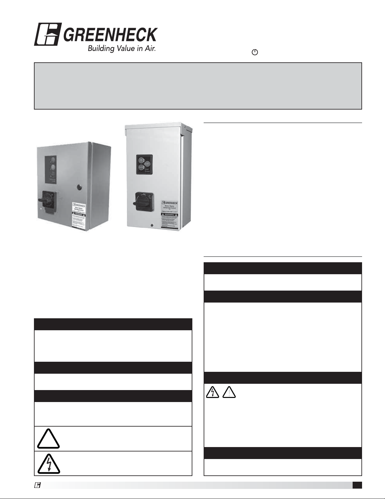
NEMA 4X
304 Stainless Steel
Enclosure
NEMA 3R
16ga. Steel Enclosure
Our Commitment ............................4
Safety Instructions
™
Precautions and Warnings
To prevent injury and property damage, follow these
instructions. Failure to adhere to installation/operation
procedures and all applicable codes may result in
hazards as indicated by warning codes outlined below:
DANGER
Indicates an imminently hazardous situation which,
if not avoided, will result in death or serious injury.
This signal word is to limited to the most extreme
situations.
WARNING
Indicates a potentially hazardous situation which, if
not avoided, could result in death or serious injury.
CAUTION
Indicates a potentially hazardous situation which, if
not avoided, may result in minor or moderate injury. It
may also be used to alert against unsafe practices.
This is the safety alert symbol. Read and
!
follow instructions carefully to avoid a
!
dangerous situation.
This symbol alerts the user to the presence
of “dangerous voltage” inside the product
that might cause harm or electrical shock.
DANGER
Equipment can start automatically. Lockout/tagout
before servicing.
CAUTION
As with all electrical products, read manual
thoroughly. Only qualified, expert personnel should
perform maintenance and installation. Contact the
nearest authorized service facility for examination,
repair, or adjustment. Do not disassemble or repair
unit unless described in this manual; death or
injury to electrical shock or fire hazard may result.
Specifications and manual data subject to change.
Consult factory for additional information.
DANGER
HAZARDOUS VOLTAGE
!
• Disconnect and lock out all power before installing
or servicing equipment.
• This equipment may require locking out multiple
power sources prior to service.
• Install and wire in accordance with all applicable
local and national electrical and construction codes.
WARNING
FAILURE TO FOLLOW THESE INSTRUCTIONS
MAY RESULT IN DEATH OR SERIOUS INJURY.
®
Motor Starter Advanced Control
1
Installation
Wiring Schematics
Mounting
Mount the starter on a vertical surface, with the line
terminals facing up. Install using 1/4-inch diameter
hardware suitable for the mounting surface.
WARNING
• To maintain overcurrent and short circuit protection,
the manufacturer’s instructions for selecting current
elements and setting the instantaneous-trip circuit
breaker must be followed.
• Tripping of the instantaneous-trip circuit breaker
is an indication that a fault current has been
interrupted. Current-carrying components of the
magnetic motor controller should be examined and
replaced if damaged to reduce the risk of fire or
electric shock.
• Do not locate starter in an environment subject to
flammable gases, dusts or materials. Contact arcing
can induce explosion or fire.
• Locate starter in a location appropriate to enclosure
ratings and operational ratings. (e.g. NEMA-1 should
only be located in a dry, protected environment).
• Do not allow any metal shavings or debris from
installation to enter enclosure.
Wiring
Wire main power input and motor leads to the
appropriate terminals tightened to specified torques
indicated in the torque table. Use only copper
conductors rated at least 60°C for applications less
than 100A and at least 75°C ≥ 100A. Maintain proper
clearances and verify that no possibility of an electrical
short exists between the power conductors or
enclosure. Ensure that wires are not under stress and
all insulation is intact. Verify voltage input matches label
and the control power is tapped per schematic.
Low Voltage Wiring
Automation system control wiring should be run in
a separate conduit. The control terminals accept
26~14AWG wire torqued to 3.5 in-lb.
Torque Table
NEMA
Size
00 15.6 18 20
0 15.6 18 20
1 15.6 18 20
Input (lb-in) Output (lb-in)
Standard Combination Motor Leads
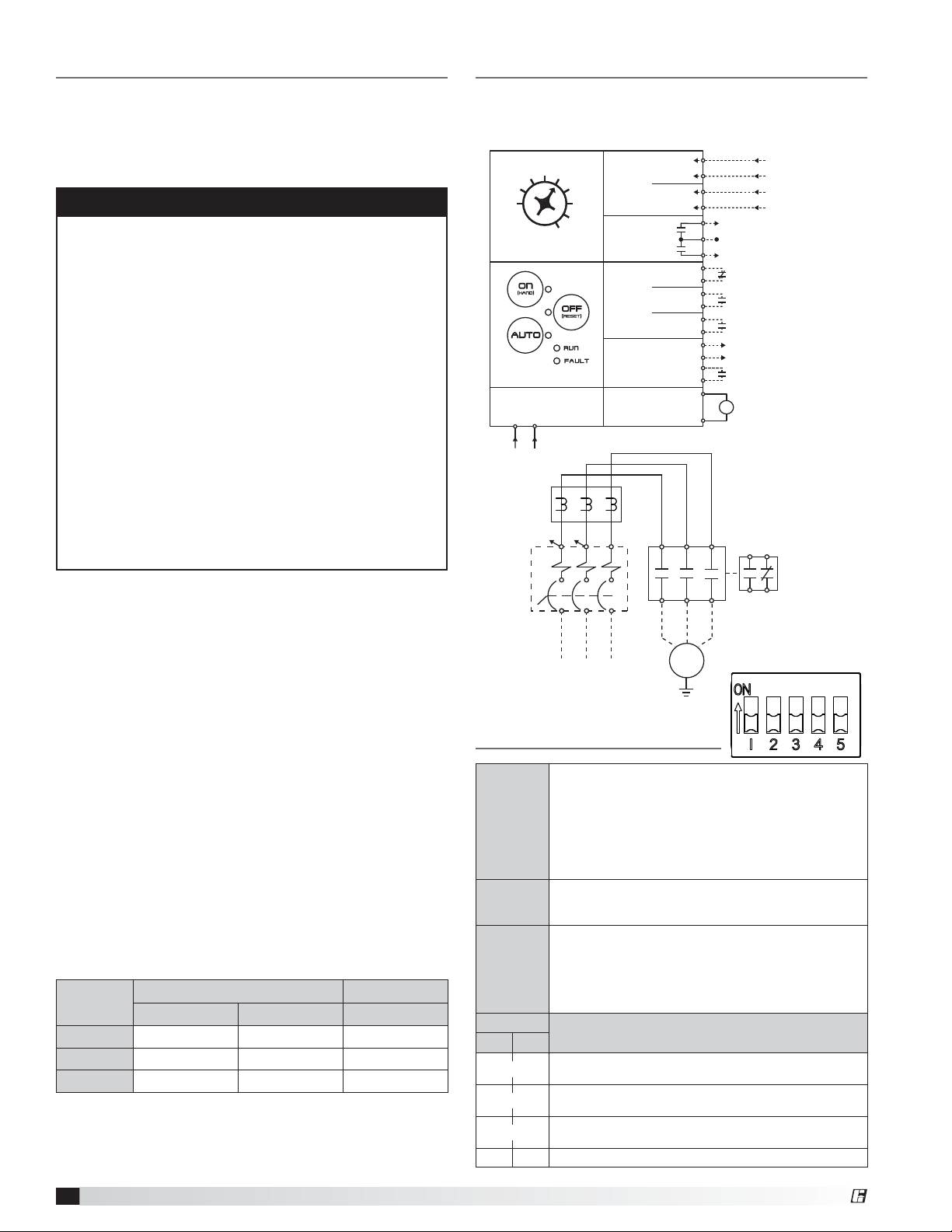
Standard product wiring diagram shown. As-built
product wiring may vary. Product wiring diagram located
on starter enclosure.
5
1
FLA (A)
Overload Setting
PCB Power
H1 H4
MCP
(Optional)
208-600VAC
Input
10
Keypad
15
OL
H1
20
25
30
35
40
208-600VAC
60VA Max.
H4
Voltage
Inputs
Relay
Outputs
Dry
Inputs
Actuator
Control
Contactor
Coil
L3L1 L2
Fireman’s
Limit Switch
M
Auto Run
Override
Shut Down
Permissive
Auto Run
Control
T1 T3
T2
MTR
3PH
12-250VAC/DC Input
12-250VAC/DC Input
Status
Common
Fault
Normally
Closed Input
Normally
Open Input
Normally
Open Input
24VDC,
1A Output
Normally
Open Input
24VDC output
24V
A1
to 24VAC
Output to
M
contactor coil
A2
contactor coil
434431
32
AUX
CONT
Program Switches
Smartstart Bypass: Bypasses the Smartstart features
when on. Smartstart protects the motor by detecting
SWITCH
1
SWITCH
2
SWITCH
3
SWITCH
45
ON ON
OFF OFF
ON OFF
OFF ON
several common potentially damaging fault conditions.
When Smartstart is active, the starter will shut off
under the following conditions: if locked rotor condition
is present for 0.5 seconds, if the motor takes more
than 10 seconds to start, or if the FLA setting is
determined to be incorrect.
Selects overload trip Class 10 when on and overload
trip Class 20 when off. If trip Class 20 is selected
Smartstart is bypassed. Default: ON
(ON) - Fault reset: Depress the “OFF” button for 5
seconds to reset a fault trip. Starter will return to “OFF”
mode.
(OFF) - Automatic Fault Reset: The starter will make 3
attempts at an auto fault reset separated by 5 minutes
intervals. Also allows manual reset as above.
Power Fail Modes
Default Mode - Always return to last mode with no
delay in the event of a power failure.
Default Mode - Always return to last mode with no
delay in the event of a power failure.
Always return to last mode with a 10 second delay in
the event of a power failure.
Upon a power failure, return to off mode.
Motor Starter Advanced Control
2
®
 Loading...