


Model GRRS
Fire Ready Hood
®
Installation, Operation and Maintenance Manual
Please read and save these instructions for future reference. Read carefully before attempting to assemble, install, operate or maintain the product described. Protect yourself and others by observing all safety information. Failure to comply with instructions could result in personal injury and/or property damage!
WARNING
To reduce the risk of fire, electric shock, or injury to persons, observe the following:
•Use this unit only in the manner intended by the manufacturer.
•Before servicing or cleaning unit, switch power off at service panel and lock the service disconnecting means to prevent power from being switched on accidentally. When the service disconnecting means cannot be locked, securely fasten a prominent warning device, such as a tag, to the service panel.
•Installation work and electrical wiring must be done by a qualified person(s) in accordance with all applicable codes and standards, including fire rated construction codes and standards.
•Sufficient air is needed for proper combustion and exhausting of gases through the flue (chimney) of fuel burning equipment to prevent backdrafting. Follow the heating equipment
manufacturer’s guideline and safety standards such as those published by the National Fire Protection Association (NFPA), and the American Society
of Heating, Refrigeration and Air Conditioning Engineers (ASHRAE), and the local code authorities.
•When cutting or drilling into wall or ceiling, do not damage electrical wiring and other hidden utilities.
•To reduce the risk of fire or electric shock, do not use this range hood with an additional speed control device.
•Ducted fans must always be vented to the outdoors.
•To reduce the risk of fire, use only metal ductwork.
•Use with approved wiring only.
•This unit must be grounded.
REPORT #1293
Listed to UL 300A Standard
WARNING
To reduce the risk of range top grease fire:
•Never leave surface units unattended at high settings. Boilovers cause smoking and greasy spillovers that may ignite. Heat oils slowly on low or medium settings.
•Always turn hood ON when cooking at high heat or when cooking flaming foods.
•Clean ventilation fans frequently. Grease should not be allowed to accumulate on fan or filter.
•Use proper pan size. Always use cookware appropriate for the size of the surface element.
To reduce the risk of injury to persons in the event of a range top grease fire, observe the following:*
•SMOTHER FLAMES with a close-fitting lid, cookie sheet, or metal tray, then turn off the burner. BE CAREFUL TO PREVENT BURNS. If the flames do not go out immediately, EVACUATE AND CALL THE FIRE DEPARTMENT.
•NEVER PICK UP A FLAMING PAN. You may be burned.
•DO NOT USE WATER, including wet dishcloths or towels - violent steam explosion will result.
*Based on “Kitchen Fire Safety Tips” published by NFPA.
Fire Ready Hood 1
®

Table of Contents
Receiving, Unpacking, Handling & Storage . . . . . . . 2 Model Number Code. . . . . . . . . . . . . . . . . . . . . . . . . 3 Parts Checklist . . . . . . . . . . . . . . . . . . . . . . . . . . . . . 3 Exploded View. . . . . . . . . . . . . . . . . . . . . . . . . . . . . . 3 Sample Installations . . . . . . . . . . . . . . . . . . . . . . . . . 4 Preparing the Install Location
Mounting Bracket. . . . . . . . . . . . . . . . . . . . . . . . . . 5 Ductwork . . . . . . . . . . . . . . . . . . . . . . . . . . . . . . . . 5 Static Pressure Testing . . . . . . . . . . . . . . . . . . . . . 5 Fans . . . . . . . . . . . . . . . . . . . . . . . . . . . . . . . . . . . . 6 Accessories . . . . . . . . . . . . . . . . . . . . . . . . . . . . . . 6
Installation
Installation Elevation . . . . . . . . . . . . . . . . . . . . . . . 7 Mounting Bracket. . . . . . . . . . . . . . . . . . . . . . . . . . 7 Installing Hood onto Mounting Bracket. . . . . . . . . 8 Installing the Fan . . . . . . . . . . . . . . . . . . . . . . . . . . 9
Range Element Disconnect Installation
Gas Disconnect Valve . . . . . . . . . . . . . . . . . . . . . 10 Electrical Disconnect Box . . . . . . . . . . . . . . . . . . 10
Installing Accessories
ClockBox . . . . . . . . . . . . . . . . . . . . . . . . . . . . . . . 11 Remote ADA Switches. . . . . . . . . . . . . . . . . . . . . 11 Manual Pull Station . . . . . . . . . . . . . . . . . . . . . . . 11 Ductwork . . . . . . . . . . . . . . . . . . . . . . . . . . . . . . . 11
Electrical Installation
Main Control Power . . . . . . . . . . . . . . . . . . . . . . . 12 Electric Disconnect Box. . . . . . . . . . . . . . . . . . . . 13 Gas Disconnect Valve . . . . . . . . . . . . . . . . . . . . . 13 Inline/Wall Mount Fan . . . . . . . . . . . . . . . . . . . . . 14 ClockBox . . . . . . . . . . . . . . . . . . . . . . . . . . . . . . . 14 Remote ADA Switches. . . . . . . . . . . . . . . . . . . . . 14 Fire Alarm System Connections . . . . . . . . . . . . . 14 Wiring Diagram . . . . . . . . . . . . . . . . . . . . . . . . . . 15 ClockBox Wiring Diagram . . . . . . . . . . . . . . . . . . 16
Operation. . . . . . . . . . . . . . . . . . . . . . . . . . . . . . . . . 17 Environmental Monitoring / Pre-Suppression
Functions . . . . . . . . . . . . . . . . . . . . . . . . . . . . . . . 17 Accessing the Internal Components. . . . . . . . . . . . 18 ClockBox Operation and Navigation . . . . . . . . . . . 19 Test Tank and Demonstration . . . . . . . . . . . . . . . . . 20 Controller Schematic. . . . . . . . . . . . . . . . . . . . . . . . 21
Alarm Connections. . . . . . . . . . . . . . . . . . . . . . . . 21 Self-Monitoring System. . . . . . . . . . . . . . . . . . . . . . 22 After an Actuation . . . . . . . . . . . . . . . . . . . . . . . . 23 How to Reset the Suppression System. . . . . .23-24 Maintaining the System. . . . . . . . . . . . . . . . . . . . . . 25
Inspection Procedures
Nozzle Caps. . . . . . . . . . . . . . . . . . . . . . . . . . . . . 25 Fusible Link System. . . . . . . . . . . . . . . . . . . . . . . 25 10 Year Maintenance. . . . . . . . . . . . . . . . . . . . . . . . 25 Lighting . . . . . . . . . . . . . . . . . . . . . . . . . . . . . . . . . . 25 Removing the Extinguisher Tank. . . . . . . . . . . . . . . 26 Service and Recertification Schedule . . . . . . . . . . . 26 Replacement Parts . . . . . . . . . . . . . . . . . . . . . . . . . 26 Maintenance Log. . . . . . . . . . . . . . . . . . . . . . . . . . . 27 Our Commitment. . . . . . . . . . . . . . . . . . . . . . . . . . . 28
Receiving
Upon receiving the product, check to ensure all items are accounted for by referencing the delivery receipt or packing list. Inspect each crate or carton for shipping damage before accepting delivery. Alert
the carrier of any damage detected. The customer will make notation of damage (or shortage of items) on the delivery receipt and all copies of the bill of lading which is countersigned by the delivering carrier. If damaged, immediately contact your Greenheck Representative. Any physical damage to the unit after acceptance is not the responsibility of Greenheck Fan Corporation.
Unpacking
Verify that all required parts and the correct quantity of each item have been received. If any items are missing, report shortages to your local representative to arrange for obtaining missing parts. Confirmation of shipment(s) must be limited to only items on the bill of lading.
Handling
Handle in such a manner as to keep from scratching or chipping the coating. Damaged finish may reduce ability of unit to resist corrosion.
Storage
Units are protected against damage during shipment. If the unit cannot be installed and operated immediately, precautions need to be taken to prevent deterioration of the unit during storage. The user assumes responsibility of the unit and accessories while in storage. The manufacturer will not be responsible for damage during storage. These suggestions are provided solely as a convenience to the user.
The ideal environment for the storage of units and accessories is indoors, above grade, in a low humidity atmosphere which is sealed to prevent the entry of blowing dust, rain, or snow. Temperatures should be evenly maintained between 30°F (-1°C) and 110°F (43°C). All accessories must be stored indoors in a clean, dry location.
2 Fire Ready Hood
®
Model Number Code
GRRS - 30 - F - E - D - N
Type |
|
|
|
|
|
|
|
|
|
|
|
|
|
|
|
|
|
|
|
|
|
|
|
NFPA 101 Compliance |
|
|
|
|
|
|
|
|
|
|
|
|
|
|
|
||||||||||
Residential |
|
|
|
|
|
|
|
|
|
|
|
|
|
|
|
|
X - Noncompliant |
|||||||
Range |
|
|
|
|
|
|
|
|
|
|
|
|
|
|
|
|
N - Compliant |
|||||||
Suppression |
|
|
|
|
|
|
|
|
|
|
|
|
|
|
|
|
|
|||||||
Length |
|
|
|
|
|
|
|
|
|
|
|
|
|
|
|
|
|
|
External Fan Type |
|||||
|
|
|
|
|
|
|
|
|
|
|
|
|
|
|
|
|
|
|||||||
|
|
|
|
|
|
|
|
|
|
|
|
|
|
|
|
D - Inlet Duct |
||||||||
30 inches |
|
|
|
|
|
|
|
|
|
|||||||||||||||
|
|
|
|
|
|
|
|
|
W - Wall Mount |
|||||||||||||||
36 inches |
|
|
|
|
|
|
|
|
|
|||||||||||||||
|
|
|
|
|
|
|
|
|
|
|
|
|
|
|||||||||||
Ventilation |
|
|
|
|
|
|
|
|
|
|
|
Range Disconnect Type |
||||||||||||
|
|
|
|
|
|
|
|
|
|
|
||||||||||||||
F - Integral Fan - Front Recirculation |
|
|
E - Electric |
|||||||||||||||||||||
R - Integral Fan - Rear Discharge |
|
|
G - Gas |
|||||||||||||||||||||
T - External Fan - Top Discharge |
|
|
D - Dual (gas and electric) |
|||||||||||||||||||||
Example: GRRS-30-F-D-N
Greenheck RRS, 30 inches long, with front fan discharge, with dual element disconnect, NFPA 101 Compliant
Parts Checklist
Hood
Back support mounting bracket
External fan (Inline / Wall Mount / None)
•25 ft. plenum rated wire for plug and play connection
8 ft. of metal clad wire for hood power connection (marked with red tape)
Gas disconnect valve (optional)
•6 ft. shielded control wire for plug and play connection
Electrical disconnect box (optional)
•6 ft. shielded control wire for plug and play connection
8 ft. of metal clad wire for gas disconnect/electrical disconnect connection (marked with black tape)
Remote switches, ADA (optional)
Manual Pull Kit (optional) consisting of the following:
•Pull Box (1)
•Pull Face (1)
•Elbow Pulley (3)
•25 ft. Cable and Pin
The ClockBox (optional)
•20 ft. shielded control wire for plug and play connection
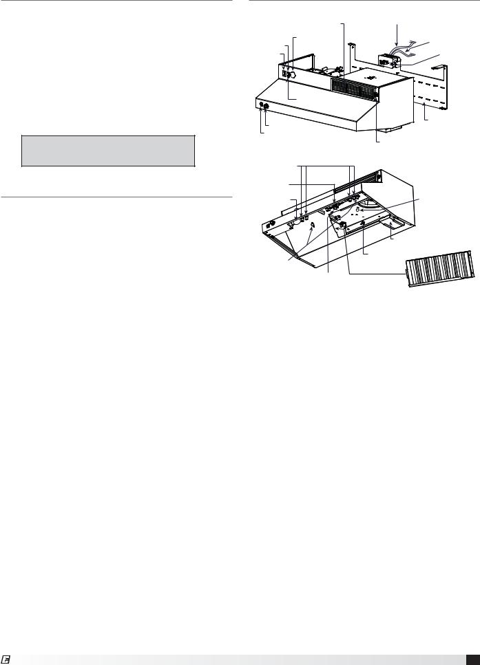
Exploded View
|
Recirculating Vent |
Electrical Disconnect |
|
|
(Black Tape) |
||
|
(recirculating model) |
||
|
|
||
|
Extinguisher |
110 VAC Power Supply |
|
|
(Red Tape) |
||
Reset Switch |
Pressure Gauge |
||
|
|||
|
|
||
Power Switch |
|
Junction Box |
|
|
|
||
|
LED Status Light |
|
|
Fan Speed Knob |
Back Support |
||
Mounting Bracket |
|||
Light Switch |
|
|
|
|
|
Thumbscrew to remove vent |
|
|
|
on some models |
|
Discharge Nozzles |
|
|
|
with protective caps |
|
|
|
Fusible Link |
|
|
|
Light Bulb |
|
Thumbscrews (2x) |
|
|
|
(inline models) |
|
|
|
Grease Tray |
|
Thumb Nut (3x)
Low Temperature
Switches
High Temperature
Switch
Grease Filter
Fire Ready Hood 3
®
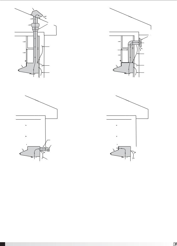
Sample Installations |
|
|
|
|
Roof Cap |
|
|
|
|
(by others) |
|
|
|
|
10 in. Ductwork |
|
|
|
|
Inline Duct Fan |
7 in. to 10 in. Transition |
|
|
|
|
|
|
|
|
(provided) |
|
|
|
|
|
|
|
|
Wall Mount Fan Box |
|
|
|
|
with Access Cover for |
|
|
|
|
Service and Mounting |
|
|
|
|
(provided) |
Soffit |
|
Soffit |
|
Fan |
|
|
|
|
|
|
Plenum Ready |
|
|
|
|
Supply Cable to Fan |
7 in. Ductwork |
|
|
Cabinet |
(provided) |
Cabinet |
|
Plenum Ready |
|
|
|
||
|
|
|
Supply Cable to Fan |
|
|
|
|
|
|
|
|
|
|
(provided) |
Range Hood |
110 VAC Supply Cable |
Range Hood |
|
110 VAC Supply Cable |
(provided) |
(provided) |
|
||
|
(provided) |
|
|
(provided) |
|
Power Disconnect Cable |
|
|
Power Disconnect Cable |
Airflow |
(provided) |
|
Airflow |
(provided) |
|
|
|
||
External Fan | Inline Fan |
|
External Fan | Wall Mount Fan |
|
|
|
Soffit |
|
|
|
|
|
|
|
|
|
|
|
|
|
|
|
|
|
|
Soffit |
|
|
|
|
|
|
|
|
|
|
|
|
|
|
|
||
|
|
|
|
|
|
|
|
|
|
|
|
|
|
|
|
|
|
|
|
|
|
|
|
|||||||||||||
Cabinet |
|
|
|
|
|
|
|
|
|
|
|
|
|
|
3½ x 12-in. Ductwork |
|
Cabinet |
|
|
|
|
|
|
|
|
|
|
|
|
|
|
|
||||
|
|
|
|
|
|
|
|
|
|
|
|
|
|
|
|
|
|
|
|
|
|
|
|
|
|
|
|
|
|
|||||||
|
|
|
|
|
|
|
|
|
|
|
|
|
|
|
|
|
|
|
|
|
|
|
|
|
|
|
|
|||||||||
|
|
|
|
|
|
|
|
|
|
|
|
|
|
|
|
|
|
|
|
|||||||||||||||||
|
|
|
|
|
|
|
|
|
|
|
|
|
|
|
|
|
|
|
|
|
|
|
|
|
|
|
|
|
|
|
|
|
|
|||
|
|
|
|
|
|
|
|
|
|
|
|
|
|
|
|
|
|
Wall Cap |
|
|
|
|
|
|
|
|
|
|
|
|
|
|
|
|
|
|
|
|
|
|
|
|
|
|
|
|
|
|
|
|
|
|
|
|
|
|
|
|
|
|
|
|
|
|
|||||||||
Range Hood |
|
|
|
|
|
|
Range Hood |
|
|
|
|
|
|
|
|
|
|
|
|
|||||||||||||||||
|
|
|
|
|
|
|
|
|
|
|
|
|
|
|
|
|
|
|
|
|
|
|
|
|
|
|||||||||||
|
|
|
|
|
|
|
|
|
|
|
|
|
(by others) |
|
|
|
|
|
|
|
|
|
|
|
|
|
||||||||||
(provided) |
|
|
|
|
|
|
|
|
|
|
(provided) |
|
|
|
|
|
|
|
||||||||||||||||||
|
|
|
|
|
|
|
|
|
|
|
|
|
|
|
|
110 VAC Supply Cable |
|
|
|
|
|
|
|
|
|
|
|
|
|
|
|
|
|
110 VAC Supply Cable |
||
|
|
|
|
|
|
|
|
|
|
|
|
|
|
|
|
|
|
|
|
|
|
|
|
|
|
|
|
|
|
|||||||
|
|
|
|
|
|
|
|
|
|
|
|
|
|
|
|
(provided) |
|
|
|
|
|
|
|
|
|
|
|
|
|
|
|
|
|
(provided) |
||
|
|
|
|
|
|
|
|
|
|
|
|
|
|
|
Power Disconnect Cable |
|
|
|
|
|
|
|
|
|
|
|
|
|
|
|
|
Power Disconnect Cable |
||||
|
|
|
|
Airflow |
|
|
|
|
|
|
|
|
|
|
Airflow |
|||||||||||||||||||||
|
|
|
|
|
|
|
|
|
|
|
|
|
|
|
|
|
|
|
||||||||||||||||||
|
|
|
|
|
|
|
|
|
|
|
|
|
|
|
|
|
|
|
(provided) |
|||||||||||||||||
|
|
|
|
|
|
|
|
|
|
|
|
|
|
|
(provided) |
|
|
|
|
|
|
|
|
|
|
|
|
|
|
|
|
|||||
|
|
|
|
|
|
|
|
|
|
|
|
|
|
|
|
|
|
|
|
|
|
|
|
|
|
|
|
|
|
|
|
|
||||
|
|
|
||||||||||||||||||||||||||||||||||
Integral Fan | Rear Discharge |
|
Integral Fan | Front Recirculation |
||||||||||||||||||||||||||||||||||
|
|
|
|
|
|
|
|
|
|
|
|
|
|
|
|
|
|
|
|
|
|
|
|
|
|
|
|
|
|
|
|
|
|
|
|
|
4 Fire Ready Hood
®

Preparing the Install Location
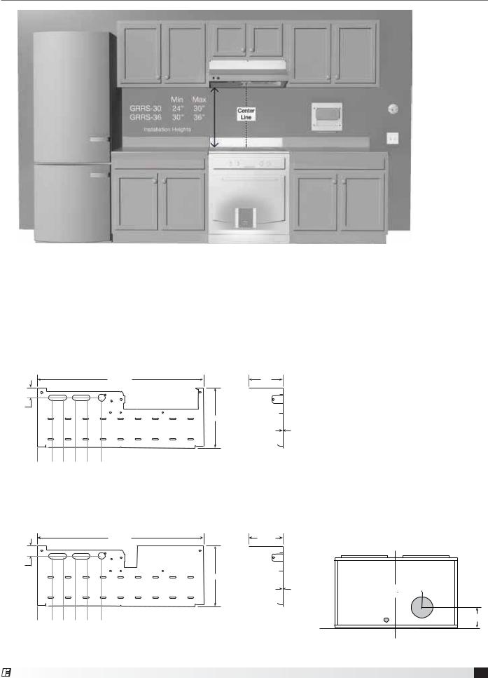
Mounting Bracket - The mounting bracket and hood must be centered over the range. If the range is not in place, the center marking should be relative to it’s final position. Refer to page 7 for bracket mounting points, rear access holes and access points.
Ductwork - The ductwork and fittings used for outside venting (if applicable) must be carefully selected to ensure that the static pressure is in line with the fan parameters. The table below displays maximum duct length allowed for the various fan options.
Hood |
NFPA 101 |
Fan Type |
Venting |
CFM |
Duct Length |
||
Width |
Compliance |
(at hood) |
(maximum) |
||||
|
|
||||||
|
|
|
|
|
|
|
|
|
|
No |
Internal |
Front (recirculating) |
140 |
Not applicable |
|
|
|
|
|
|
|
|
|
|
|
No |
Internal |
Rear Discharge |
250 |
Not applicable |
|
|
|
|
|
|
|
|
|
|
|
No |
Inline Duct Fan |
Vertical Duct |
470 |
35 feet |
|
|
|
|
|
|
|
|
|
30 inches |
No |
Exterior Wall Fan |
Vertical Duct |
150 |
20 feet |
||
|
|
|
|
|
|||
Yes |
Internal |
Front (recirculating) |
500 |
Not applicable |
|||
|
|
||||||
|
|
|
|
|
|
|
|
|
|
Yes |
Internal |
Rear Discharge |
500 |
Not applicable |
|
|
|
|
|
|
|
|
|
|
|
Yes |
Inline Duct Fan |
Vertical Duct |
510 |
35 feet |
|
|
|
|
|
|
|
|
|
|
|
Yes |
Exterior Wall Fan |
Vertical Duct |
550 |
20 feet |
|
|
|
|
|
|
|
|
|
|
|
No |
Internal |
Front (recirculating) |
140 |
Not applicable |
|
|
|
|
|
|
|
|
|
|
|
No |
Internal |
Rear Discharge |
250 |
Not applicable |
|
|
|
|
|
|
|
|
|
|
|
No |
Inline Duct Fan |
Vertical Duct |
470 |
35 feet |
|
|
|
|
|
|
|
|
|
36 inches |
No |
Exterior Wall Fan |
Vertical Duct |
150 |
20 feet |
||
|
|
|
|
|
|||
Yes |
Internal |
Front (recirculating) |
500 |
Not applicable |
|||
|
|
||||||
|
|
|
|
|
|
|
|
|
|
Yes |
Internal |
Rear Discharge |
500 |
Not applicable |
|
|
|
|
|
|
|
|
|
|
|
Yes |
Inline Duct Fan |
Vertical Duct |
510 |
35 feet |
|
|
|
|
|
|
|
|
|
|
|
Yes |
Exterior Wall Fan |
Vertical Duct |
550 |
20 feet |
|
|
|
|
|
|
|
|
|
Maximum duct length equals horizontal and vertical duct runs plus duct components such as fittings, elbows, and transitions.
For installations requiring vertical duct venting to an inline fan and NFPA 101 compliance, the hood should be adapted from a 7-inch round duct access hole to a minimum 12-inch duct.
For installations requiring vertical duct venting to an inline fan and NFPA 101 compliance is NOT required, the hood can be adapted to a minimum 10-inch duct.
WARNING
The amount of fittings and ductwork directly affects the resistance or static pressure placed on the system. If the system is not within the proper static pressure range, the heat sensors and controls will be adversely affected and will impact the proper function of the safety controls. Therefore it is required that airflow testing be recorded along with installation documentation. The air testing is accessed by the removal of the grease tray and measured with an airflow pressure gauge.
Static Pressure Testing - The magnehelic gauge test port opening is located beneath the grease tray. The static pressure needs to be measured to ensure airflows meet design criteria. The airflow is measured by attaching the gauge tubing to the magnehelic gauge inlet, and the hood fitting is attached to the grease drain hole beneath the grease tray.
A reading of 0.45 to 0.85 inches wg. is required to meet design standards. This reading will correspond to the static pressure of the ductwork, hood and fan combination.
Magnehelic Gauge
Test Port
Fire Ready Hood 5
®

Fans
For inline fans and exterior wall fans, fan location and proper mounting will be required.
If the hood system is configured for front recirculation discharge or rear discharge and NFPA 101 compliance, the unit will come equipped with a fan box. If installing under cabinets, keeping the fan box flush to the underside of cabinet will guarantee correct spacing. Otherwise, center and mark the installation area according to wall mounting bracket prior to hanging.
The following steps will be required.
1.Insert/attach the top portion of the manual pull kit conduit through the fan box.
2.Attach square duct collar to the bottom of the fan box with included hardware.
3.Attach the fan box to the mounting bracket with included 8/32 nuts, then complete the installation on the manual pull kit conduit and top/bottom unions.
When prepping a space for installation, a 4-9⁄16 inch space must be allowed between the top of the mounting bracket and the bottom of the cabinet for the fan box. The additional height of the unit should not result in reduced range clearance. Cabinets should be installed approximately 5 inches higher to accommodate the additional size of the NFPA 101 fan box assembly.
Accessories
Location restrictions will apply if the hood system supplied is provided with any of the optional accessories:
•ClockBox
•Remote ADA Switches
•Manual Pull Station
6 Fire Ready Hood
®
Installation
A
B
C D
Installation Elevation
A.Hood (30 or 36 inches)
B.Appliance (for reference purposes)
C.Range Disconnect - electric, gas or dual (optional)
D.Gas Range Element Disconnect (not shown)
E.The ClockBox. Range Element Time-Out System (optional)
F.Handicapped Accessible Control Box (optional)
G.Manual Pull Station (optional)
Mounting Bracket for a 30-inch unit
|
|
|
28-5/8 in. |
|
|
4 in. |
|
|
|
A |
|
|
B |
B |
|
|
|
|
|
|
D |
C |
B |
|
|
|
|
E |
|
|
|
|||
1-11/16 in. |
|
|
|
|
|
|
|
|
|
F |
F |
F |
F 10-5/16 in. |
|
|
|
|
|
|
1/16 in. |
|
|
|
F |
F |
F |
F |
|
|
|
A |
|
|
|
0 in. |
2-7/16 in. |
4-7/16 in. |
6-7/16 in. |
8-7/16 in. |
-15/16 in. |
|
|
|
|
|
10 |
Mounting Bracket for NFPA Installation
|
|
|
28-5/8 in. |
|
|
5-7/8 in. |
|
|
|
A |
|
|
B |
B |
|
C |
|
|
|
|
E |
D |
B |
|
|
|
|
1-5/8 in. |
|
|
|
|
|
|
|
|
|
F |
F |
F |
F 10-5/16 in. |
|
|
|
|
|
|
1/16 in. |
|
|
|
F |
F |
F |
F |
|
|
|
A |
|
|
|
0 in. |
1/2 in. |
1/2 in. |
1/2 in. |
1/2 in. |
11 in. |
|
2- |
4- |
6- |
8- |
|
EG
F
Mounting Bracket
A.Center notches
B.Critical mounting points must be secured to studs or drywall hangers.
C.Rear access to junction box connection
D.Primary access point for connections to junction box
E.Secondary access point for connections to hood (options/ accessories)
F.Additional mounting points. Secure minimum of three (3) screws per row.
Cabinet Front |
Cabinet Front |
Cabinet Bottom
7-inch Round Duct Access Hole
 7-13/16 in.
Electrical |
5-15/16 in. |
|
Access Hole |
||
|
C
L
Fire Ready Hood 7
®

Installing Hood onto Mounting Bracket
NOTE
Install manual pull station, if provided, before arming the system.
1.Lift hood onto mounting bracket and seat the lower tabs of the mounting bracket into slots in back of hood.
4.Remove the safety pin - identified with the yellow CAUTION flag from the trigger on top of the extinguisher bottle.
Safety Pin
Lower Tabs
Slots
2.While holding the hood up, hook safety cable to chain link on mounting bracket and screw nut to close the link. The hood is now in the service position.
5.Remove the safety key from the actuator arm by rotating and lifting straight upwards. The system will not actuate without completing steps 4 and 5.
Chain Link
3.Connect male plug from top of hood into female plug mounted in junction box.
CAUTION
The system is now armed.
6.Rotate hood to wall and thread the three thumb nuts to the bolts in the mounting plate. Check page 18 for location of thumb nuts.
8 Fire Ready Hood
®
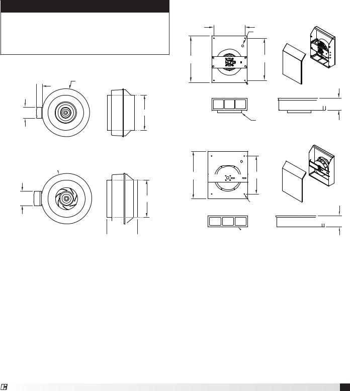
Installing Fan (if applicable)
Inline
Install fan vertically in ductwork running between the unit and roof cap.
For best results, use as few elbows or transitions as possible. If necessary, long radius elbows or bends are recommended.
To attach ductwork, use duct tape at inlet and outlet to assure a good seal. If using fan clamps, attach clamps and insert screws through clamp into inlet and outlet flanges.
CAUTION
Use sheet metal screws to secure ductwork to inlet and outlet. It is critical that the screw penetrate the metal of the flange, but not so far as to bind the impeller. It may be necessary to angle screws away from impeller.
Inline Exhaust Fan - NFPA
Ø16.00 in.
2.4375 in. 
3.75 in. |
11.875 in. |
 10.50 in.
Inline Exhaust Fan - Non-NFPA
Ø13.375 in. 
3.75 in. |
10.00 in. |
2.00 in.


 8.25 in.
Wall Mounted Fan
Fasten the fan box to an external wall via the four 0.27-inch mounting holes.
Run electrical through the 0.81-inch hole towards the top right corner of the box.
Attach ductwork using duct sealant, caulk, or tape to all seams to prevent air leakage and maximize air performance.
For best results use as few elbows or transitions as possible. If necessary, long radius elbows or bends are recommended.
Wall Fan - NFPA
|
11.625 in. |
|
Ø0.81 in. |
17.8125 in. |
15.875 in. |
 13.375 in.
  Ø0.27 in. (4X)
MOUNTING HOLES
 4.625 in.
Ø8 IN. VENT DUCT CONNECTION
Wall Fan - Non-NFPA
 12.00 in.

17.50 in.  14.00 in.
Ø0.27 in. (4X)  14.625 in.

 MOUNTING HOLES
 4.0625 in.
 Ø8 IN. VENT DUCT CONNECTION
Fire Ready Hood 9
®
 Loading...