


MSX
Installation, Operation and Maintenance Manual
Please read and save these instructions. Read carefully before attempting to assemble, install, operate or maintain the
product described. Protect yourself and others by observing all safety information. Failure to comply with instructions
could result in personal injury and/or property damage! Retain instructions for future reference.
1
Modular Supply Make-Up Air Unit
®
Document 470658
MSX
Make-Up Air Unit
®
®
DANGER
Always disconnect power before working on or near a
unit. Lock and tag the disconnect switch or breaker to
prevent accidental power up.
CAUTION
When servicing the unit, motor may be hot enough
to cause pain or injury. Allow motor to cool before
servicing.
IMPORTANT
All factory provided lifting lugs must be used when
lifting any unit. Failure to comply with this safety
precaution could result in property damage, serious
injury or death.
WARNING
Disconnect all electrical power to the fan and secure
to the “OFF” position prior to inspection or servicing.
Failure to comply with this safety precaution could
result in serious injury or death.
WARNING
Improper installation, adjustment, alteration, service
or maintenance can cause property damage, injury
or death. Read the installation, operating and
maintenance instructions thoroughly before installing
or servicing this equipment.
General Safety Information
Only qualified personnel should install this unit.
Personnel should have a clear understanding of these
instructions and should be aware of general safety
precautions. Improper installation can result in electric
shock, possible injury due to coming in contact with
moving parts, as well as other potential hazards. Other
considerations may be required if high winds or seismic
activity are present. If more information is needed,
contact a licensed professional engineer before moving
forward.
1. Follow all local electrical and safety codes, as well as
the National Electrical Code (NEC), the National Fire
Protection Agency (NFPA), where applicable. Follow
the Canadian Electric Code (CEC) in Canada.
2. The rotation of the wheel is critical. It must be free
to rotate without striking or rubbing any stationary
objects.
3. Motor must be securely and adequately grounded.
4. Do not spin fan wheel faster than maximum
cataloged fan rpm. Adjustments to fan speed
significantly effects motor load. If the fan RPM is
changed, the motor current should be checked to
make sure it is not exceeding the motor nameplate
amps.
5. Do not allow the power cable to kink or come in
contact with oil, grease, hot surfaces, or chemicals.
Replace cord immediately if damaged.
6. Verify that the power source is compatible with the
equipment.
7. Never open blower access doors while the fan is
running.

2
Modular Supply Make-Up Air Unit
®
The unit should be stored at least 3½ in. (89 mm) off the
floor on wooden blocks covered with moisture proof
paper or polyethylene sheathing. Aisles between parts
and along all walls should be provided to permit air
circulation and space for inspection.
OUTDOOR — Units designed for outdoor applications
may be stored outdoors, if absolutely necessary. Roads
or aisles for portable cranes and hauling equipment are
needed.
The fan should be placed on a level surface to prevent
water from leaking into the unit. The unit should be
elevated on an adequate number of wooden blocks so
that it is above water and snow levels and has enough
blocking to prevent it from settling into soft ground.
Locate parts far enough apart to permit air circulation,
sunlight, and space for periodic inspection. To minimize
water accumulation, place all unit parts on blocking
supports so that rain water will run off.
Do not cover parts with plastic film or tarps as these
cause condensation of moisture from the air passing
through heating and cooling cycles.
Inspection and Maintenance during
Storage
While in storage, inspect fans once per month. Keep a
record of inspection and maintenance performed.
If moisture or dirt accumulations are found on parts,
the source should be located and eliminated. At each
inspection, rotate the fan wheel by hand ten to fifteen
revolutions to distribute lubricant on motor. Every three
months, the fan motor should be energized. If paint
deterioration begins, consideration should be given to
touch-up or repainting. Fans with special coatings may
require special techniques for touch-up or repair.
Machined parts coated with rust preventive should be
restored to good condition promptly if signs of rust
occur. Immediately remove the original rust preventive
coating with petroleum solvent and clean with lint-free
cloths. Polish any remaining rust from surface with
crocus cloth or fine emery paper and oil. Do not destroy
the continuity of the surfaces. Wipe thoroughly clean
with Tectyl
®
506 (Ashland Inc.) or the equivalent. For
hard to reach internal surfaces or for occasional use,
consider using Tectyl
®
511M Rust Preventive or WD-40®
or the equivalent.
REMOVING FROM STORAGE — As units are removed
from storage to be installed in their final location, they
should be protected and maintained in a similar fashion,
until the equipment goes into operation.
Prior to installing the unit and system components,
inspect the unit assembly to make sure it is in working
order.
1. Check all fasteners, set screws on the fan, wheel,
bearings, drive, motor base, and accessories for
tightness.
2. Rotate the fan wheel(s) by hand and assure no parts
are rubbing.
Receiving
Upon receiving the product check to make sure all items
are accounted for by referencing the bill of lading to
ensure all items were received. Inspect each crate for
shipping damage before accepting delivery. Notify the
carrier if any damage is noticed. The carrier will make
notification on the delivery receipt acknowledging any
damage to the product. All damage should be noted on
all the copies of the bill of lading which is countersigned
by the delivering carrier. A Carrier Inspection Report
should be filled out by the carrier upon arrival and
reported to the Traffic Department. If damaged upon
arrival, file claim with carrier. Any physical damage to
the unit after acceptance is not the responsibility of
manufacturer.
Unpacking
Verify that all required parts and the correct quantity
of each item have been received. If any items are
missing, report shortages to your local representative to
arrange for obtaining missing parts. Sometimes it is not
possible that all items for the unit be shipped together
due to availability of transportation and truck space.
Confirmation of shipment(s) must be limited to only
items on the bill of lading.
Handling
Units are to be rigged and moved by the lifting brackets
provided or by the skid when a forklift is used. Location
of brackets varies by model and size. Handle in such
a manner as to keep from scratching or chipping the
coating. Damaged finish may reduce ability of unit to
resist corrosion.
Storage
Units are protected against damage during shipment. If
the unit cannot be installed and operated immediately,
precautions need to be taken to prevent deterioration of
the unit during storage. The user assumes responsibility
of the unit and accessories while in storage. The
manufacturer will not be responsible for damage during
storage. These suggestions are provided solely as a
convenience to the user.
INDOOR — The ideal environment for the storage of
units and accessories is indoors, above grade, in a
low humidity atmosphere which is sealed to prevent
the entry of blowing dust, rain, or snow. Temperatures
should be evenly maintained between 30°F (-1°C) and
110F (43°C) (wide temperature swings may cause
condensation and “sweating” of metal parts). All
accessories must be stored indoors in a clean, dry
atmosphere.
Remove any accumulations of dirt, water, ice, or snow
and wipe dry before moving to indoor storage. To avoid
“sweating” of metal parts allow cold parts to reach room
temperature. To dry parts and packages use a portable
electric heater to get rid of any moisture build up. Leave
coverings loose to permit air circulation and to allow for
periodic inspection.

3
Modular Supply Make-Up Air Unit
®
Table of Contents
Installation
Clearance to Combustibles/Service Clearances . . 4
Indoor Unit ............................... 4
Unit Arrangement DB / HZ / UB .............. 4
Roof Mounted Unit — Arrangement DBC ......5-6
Optional Evaporative Cooling Module .......... 7
Electrical Wiring ........................... 8
Optional Electrical Heater ................... 9
Optional Evaporative Cooling Piping ........10-11
Optional Water Wizard™ ................... 12
Optional Direct Expansion (DX) Coil Piping . . . 13-14
Optional Chilled Water Coil Piping ........... 15
Optional Building Pressure Control ........... 15
Start-Up
Start-Up Check List ....................... 16
Blower ................................. 17
Optional Electric Heater .................... 18
Optional Economizer ...................... 19
Optional Evaporative Cooling Recirculating .... 20
Optional Water Wizard™ .................21-22
Operation
Optional VAV Units ........................ 23
Optional Recirculating Units ................ 24
Electrical ................................ 25
Optional Water Wizard™ ................... 26
Troubleshooting
Blower ................................. 27
Motor Overamps ......................... 28
Insufficient / Too Much Airflow .............. 29
Excessive Noise or Vibration ................ 30
Optional Electric Heater .................... 31
Optional Evaporative Cooling ............... 32
Optional Water Wizard™ ................... 33
Maintenance
Routine ...............................34-36
Fall .................................... 36
Reference
Control Center Layout / Dirty Filter Switch ..... 37
Maintenance Log .......................38-39
Our Commitment ...................Backcover
4
Modular Supply Make-Up Air Unit
®
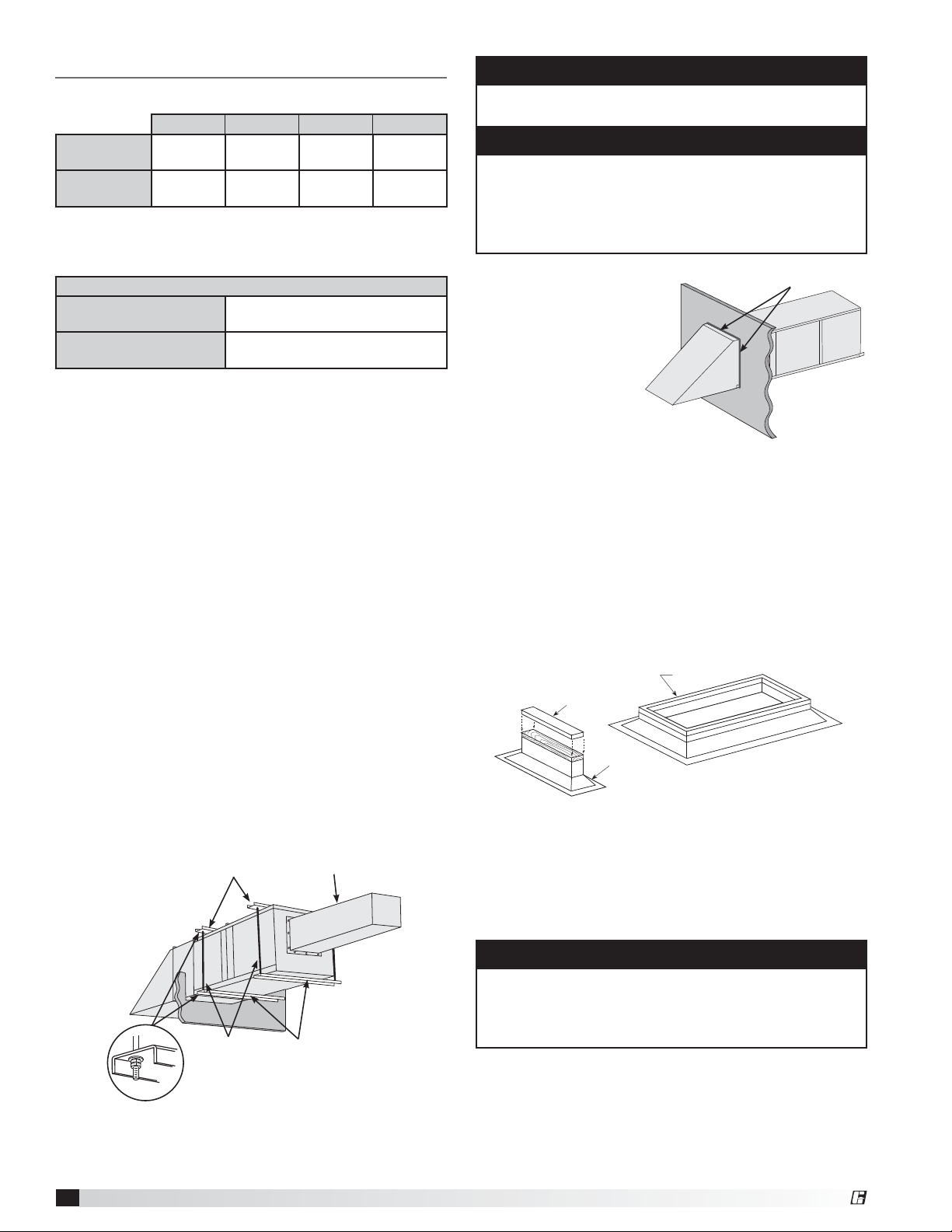
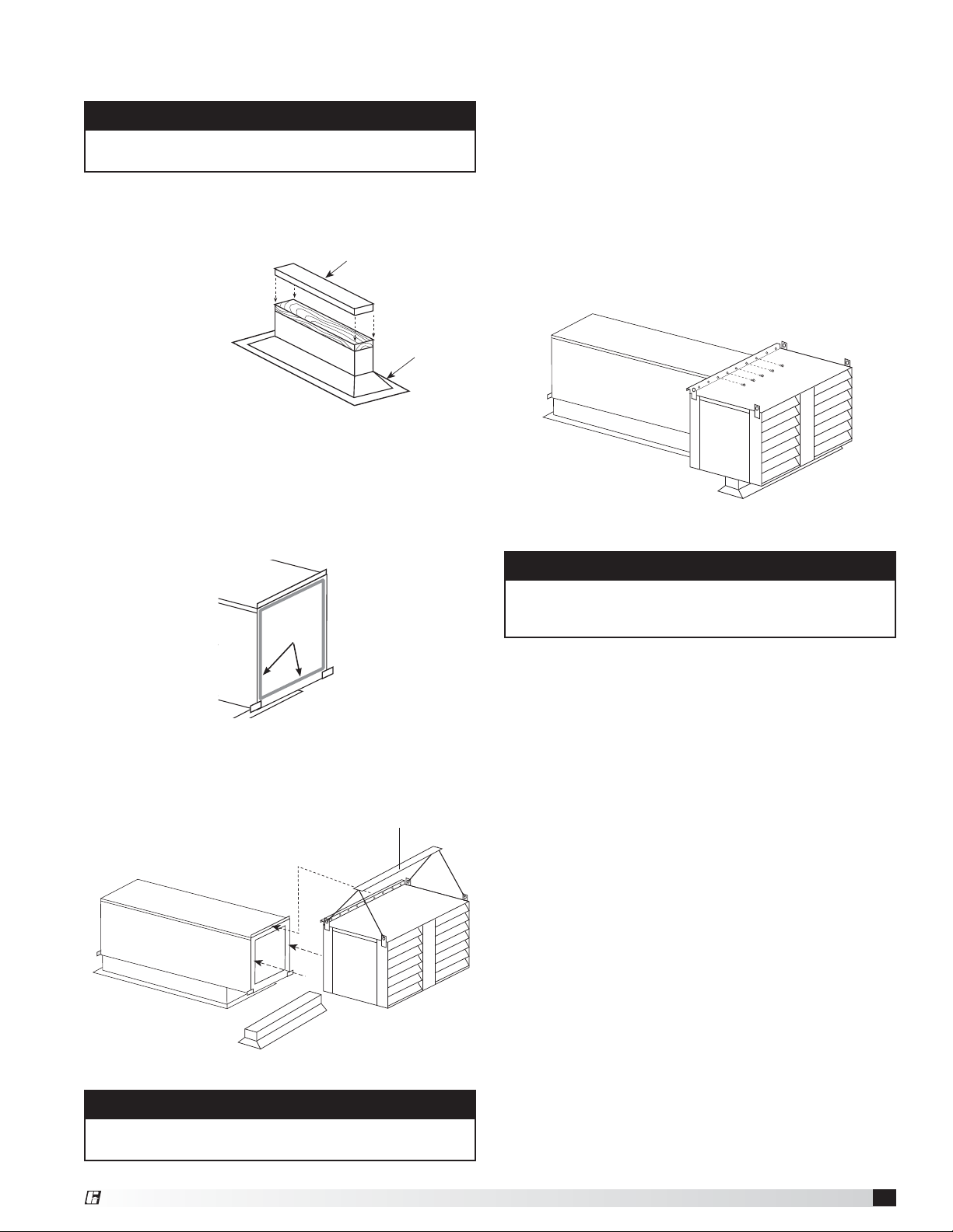
Installation of Arrangement DB / HZ / UB
1. Install Curb and/or Equipment Support(s).
Position curb/equipment support(s) on the roof
(reference the CAPS submittal for placement of curb/
equipment support(s) in relation to the unit). Verify that
unit supports are level, shim if necessary. Attach curb
to roof and flash into place. Attach the equipment
support(s) to the roof, remove metal cover, flash to
wooden nailer and reinstall cover.
Metal Cover
Equipment
Support
Roof Curb
Roof Curb and Equipment Support
2. Install Ductwork.
Good duct practices should be
followed for all ductwork. All ductwork should be
installed in accordance with SMACNA and AMCA
guidelines, NFPA 96 and all local codes. Reference the
CAPS submittal for ductwork sizes.
3. Apply Sealant. Apply an appropriate sealant around
the perimeter of the curb and duct adapter(s) to
isolate fan vibration and prevent water penetration.
NOTE
The use of a duct adapter is recommended on a
downblast (DB) arrangement to align the ductwork
with the supply unit. The duct adapter is only a guide
and is not to be used as a support for the ductwork.
3. Seal Wall Opening.
Apply sealant around
the perimeter of the
weatherhood to
prevent water
penetration and
drafts into the
building.
NOTE
Two nuts must be used on each end of each threaded
hanging rod for proper support.
NOTE
Good duct practices should be followed for all
ductwork. Ductwork should be installed in accordance
with SMACNA and AMCA guidelines, NFPA 96 and
any local codes. Reference the CAPS submittal for
duct sizes.
Sealant
Seal Wall Opening
Installation
Service Clearances
Floor Top Sides Ends
Insulated/
Units
0 inches
(0 mm)
0 inches
(0 mm)
0 inches
(0 mm)
0 inches
(0 mm)
Non Insulated
Units
0 inches
(0 mm)
6 inches
(152.4 mm)
6 inches
(152.4 mm)
6 inches
(152.4 mm)
Clearance to combustibles is defined as the minimum distance required
between the heater and adjacent combustible surfaces to ensure the
adjacent surface’s temperature does not exceed 90 degrees above the
ambient temperature.
Recommended Minimum Service Clearances
Housing 32 and less
42 inches (1066.8 mm)
on the controls side of the unit
Housing 35 and higher
48 inches (1219.2 mm)
on the controls side of the unit
Clearances for component removal (such as evaporative cooler media)
may be greater than the service clearances listed.
Installation of Indoor Unit
1. Install Hangers. Install threaded hangers from
ceiling supports. When locating hangers, allow
enough room to open access panel(s). Two nuts
must be used on the end of each threaded hanger.
Ceiling supports are supplied by others.
2. Install Unit. Using sheet metal screws, attach the
weatherhood/thru-wall/filter section to the blower/
burner section. The flange on the weatherhood/thru-
wall/filter section should overlap the flange on the
blower/burner section.
Raise the assembled unit into place.
Using two nuts per hanger, fasten the unit supports
to the hangers under the unit. Appropriate unit
supports, such as the optional hanging bracket kit or
c-channel and angle iron (supplied by others) should
be used.
Using self tapping screws, attach ductwork to unit.
In order to prevent the unit from swinging and
to provide a safe environment for service and
maintenance, additional measures must be taken to
secure the unit in all directions.
Unit Supports
Ceiling Supports
Hangers
Ductwork
Indoor
Mounting
5
Modular Supply Make-Up Air Unit
®
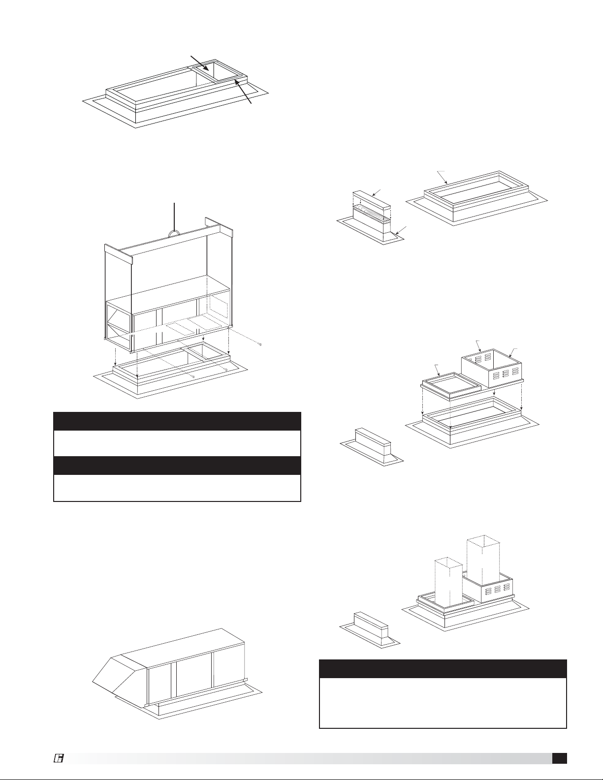
Supply Air Ductwork
(Arrangement DB only)
Sealant
Ductwork
4. Install Unit. Use a crane and a set of spreader bars
hooked to the factory lifting lugs to lift and center the
unit on the curb/equipment support(s).
Use self-tapping sheet metal screws to fasten the
unit to the curb/equip support(s).
Setting Unit
5. Assemble and Attach Weatherhood. The
weatherhood can now be assembled and attached
to the unit. Detailed assembly instructions can
be found with the weatherhood. If the optional
evaporative cooling module was selected, this
step does not apply, refer to the Installation of the
Optional Evaporative Cooling Module section.
6. Seal Weatherhood Seam. Using an appropriate
sealant, seal the seam between the weatherhood
and the unit.
Complete Rooftop Installation
NOTE
The use of all lifting lugs and a set of spreader bars is
mandatory when lifting the unit.
NOTE
Some units come with the weatherhood attached and
Step 5 may not apply.
Installation of Roof Mounted Unit
Arrangement DBC
1. Install Curb/Equipment Support(s). Position
curb/equipment support(s) on the roof (reference the
CAPS submittal for placement of curb/equipment
support(s) in relation to the unit). Verify that all unit
supports are level, shim if necessary. Attach curb
to roof and flash into place. Attach the equipment
support(s) to the roof, remove metal cover, flash to
wooden nailer and reinstall cover.
2. Install Combination Extension. Install
combination extension over curb. Lag into place
using wood screws. Locate the extension so the tall
vented side is over the exhaust opening.
3. Install Ductwork. Good duct practices should be
followed for all ductwork. All ductwork should be
installed in accordance with SMACNA and AMCA
guidelines, NFPA 96 and any local codes. Reference
the CAPS submittal for ductwork size and location.
Supply
Ductwork
by Others
Exhaust
Ductwork
by Others
NOTE
The use of a duct adapter is recommended on a
downblast (DBC) arrangement to align the ductwork
with the supply unit. The duct adapter is only a guide
and is not to be used as a support for the ductwork.
Metal Cover
Equipment
Support
Roof Curb
Roof Curb and Equipment Support
Exhaust
Supply
1 inch
Inside Flange
Combination Extension
Ductwork
6
Modular Supply Make-Up Air Unit
®
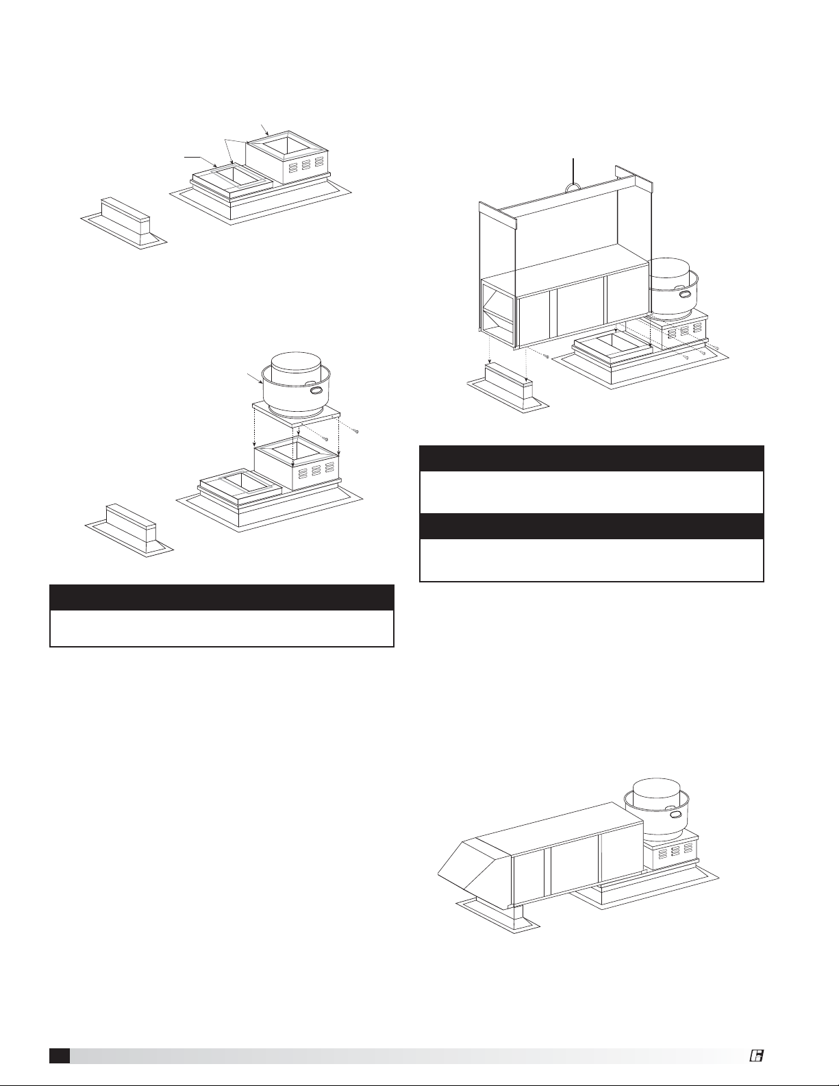
7. Install Supply Unit. Use a crane and a set of
spreader bars hooked to the factory lifting lugs to
lift and center the unit on the extension/equipment
support(s).
Use self-tapping sheet metal screws to fasten the
unit to the extension/equipment support(s).
8. Assemble and Attach Weatherhood. The
weatherhood can now be assembled and/or
attached to the unit. Detailed assembly instructions
can be found with the weatherhood. If the optional
evaporative cooling module was selected, this step
does not apply, refer to the next section, Installation
of the Optional Evaporative Cooling Module.
9. Seal Weatherhood Seam. Using an appropriate
sealant, seal the seam between the weatherhood
and the unit.
NOTE
The use of all lifting lugs and a set of spreader bars is
mandatory when lifting unit.
NOTE
Some units come with the weatherhood attached and
Step 8 may not apply.
Installing Supply Unit
Complete Combination Installation
6. Install Exhaust Options. Install optional hinge kit
with restraining cables and grease trap with drain
connection.
5. Install Exhaust Fan. Fasten exhaust fan to curb
extension with self-tapping sheet metal screws.
Installing the exhaust fan prior to the supply unit
will allow for easier installation of options.
4. Apply Sealant. Apply an appropriate sealant
around the perimeter of the curb and duct
adapter(s) to isolate fan vibration and prevent water
penetration.
NOTE
NFPA 96 requires the exhaust fan to be hinged.
Supply Duct with
Duct Adapter Installed
Exhaust Duct
Installed
Sealant
Sealing Ductwork
Model CUBE
Exhaust Fan
Installing Exhaust Fan
7
Modular Supply Make-Up Air Unit
®
Installation of Evaporative Cooling
Module (optional)
NOTE
Small evaporative coolers ship attached to the base
unit and require no additional mounting.
NOTE
The use of all lifting lugs and a set of spreader bars is
mandatory when lifting the evaporative cooling module.
NOTE
When mounting the evaporative cooler, it is important
that it is level to ensure proper operation and water
drainage.
Metal Cover
Equipment
Support
Equipment Support
Placing Evaporative Module
Securing Evaporative Module
1. Locate Equipment Support(s). Position equipment
support(s) on the roof (reference the CAPS submittal
for placement of equipment support(s) in relation
to the unit).
Verify that all
unit supports
are level, shim
if necessary.
Attach
equipment
support to the
roof, remove
metal cover,
flash to wooden
nailer and reinstall cover.
4. Secure Cooling Module to Unit. Use self-tapping
screws to fasten the cooling module to the base
unit along the top and down both sides. Fasten at
the top through the flanges. To fasten the sides,
the media must be removed. To remove the media,
first remove the access panel on the evaporative
module and disconnect the evaporative pump(s). The
media will now slide out. With the media removed,
you can access the side fastening points inside the
evaporative module. With all the screws in place,
reinstall the media, reconnect the pumps and r
einstall
the access panel.
Sealant
3. Set Evaporative Cooling Module.
Use a crane
and a set of spreader bars hooked to the factory lifting
lugs to lift and center the module on the equipment
support(s). The flange on the evaporative cooler should
overlap the flange on the unit.
2. Apply Sealant. Apply an appropriate sealant around
the airstream opening to create an air tight seal.
8
Modular Supply Make-Up Air Unit
®
Installation of Electrical Wiring
IMPORTANT
Before connecting power to the unit, read and
understand the following instructions and wiring
diagrams. Complete wiring diagrams are attached on
the inside of the control center door(s).
IMPORTANT
All wiring should be done in accordance with the
latest edition of the National Electric Code ANSI/
NFPA70 and any local codes that may apply. In
Canada, wiring should be done in accordance with
the Canadian Electrical Code.
IMPORTANT
The equipment must be properly grounded. Any
wiring running through the unit in the airstream must
be protected by metal conduit, metal clad cable or
raceways.
CAUTION
If replacement wire is required, it must have a
temperature rating of at least 105°C, except for an
energy cut-off or sensor lead wire which must be
rated to 150°C.
DANGER
High voltage electrical input is needed for this
equipment. This work should be performed by a
qualified electrician.
CAUTION
Any wiring deviations may result in personal injury or
property damage. Manufacturer is not responsible
for any damage to, or failure of the unit caused by
incorrect final wiring.
IMPORTANT
Manufacturer’s standard control voltage is 24VAC.
Control wire resistance should not exceed 0.75ohms
(approximately 285 feet total length for 14gauge
wire; 455 feet total length for 12gauge wire). If the
resistance exceeds 0.75 ohms, an industrial-style
plug-in relay should be wired in place of the remote
switch. The relay must be rated for at least 5 amps
and have a 24 VAC coil. Failure to comply with these
guidelines may cause motor starters to chatter or not
pull in, resulting in contactor failures and/or motor
failures.
1. Determine the Size of the Main Power Lines.
The unit’s nameplate states the voltage and the unit’s
MCA. The main power lines to the unit should be
sized accordingly. The nameplate is located on the
outside of the unit on the control panel side.
2. Provide the Opening(s) for the Electrical
Connection. Electrical openings vary by unit size
and arrangement and are field supplied.
3. Connect the Main Power. Connect the main
power lines to the disconnect switch and main
grounding lug(s). Torque field connections to
20in.-lbs.
4. Wire the Optional Convenience Outlet. The
convenience outlet requires a separate 115 volt
power supply circuit. The circuit must include short
circuit protection which may need to be supplied by
others.
5. Wire the Optional Accessories. Reference the
Ladder Diagram on the inside of the control center
door for correct wiring of the following accessories:
• Blower Switch
• Heat Switch
• Indicating Lights
• Dirty Filter Indicator
• TSCP
• KSCP
NOTE
TSCP has number-to-number wiring.
NOTE
Large evaporative coolers may require a separate
power supply.
6. Wire the Optional Evaporative Cooler. Reference
the Ladder Diagram on the inside of the control
center door for correct wiring of the pump and the
optional auto-drain and flush.
9
Modular Supply Make-Up Air Unit
®
WARNING
Electrical Shock Hazard! Disconnect all power
sources before doing any work on the unit.
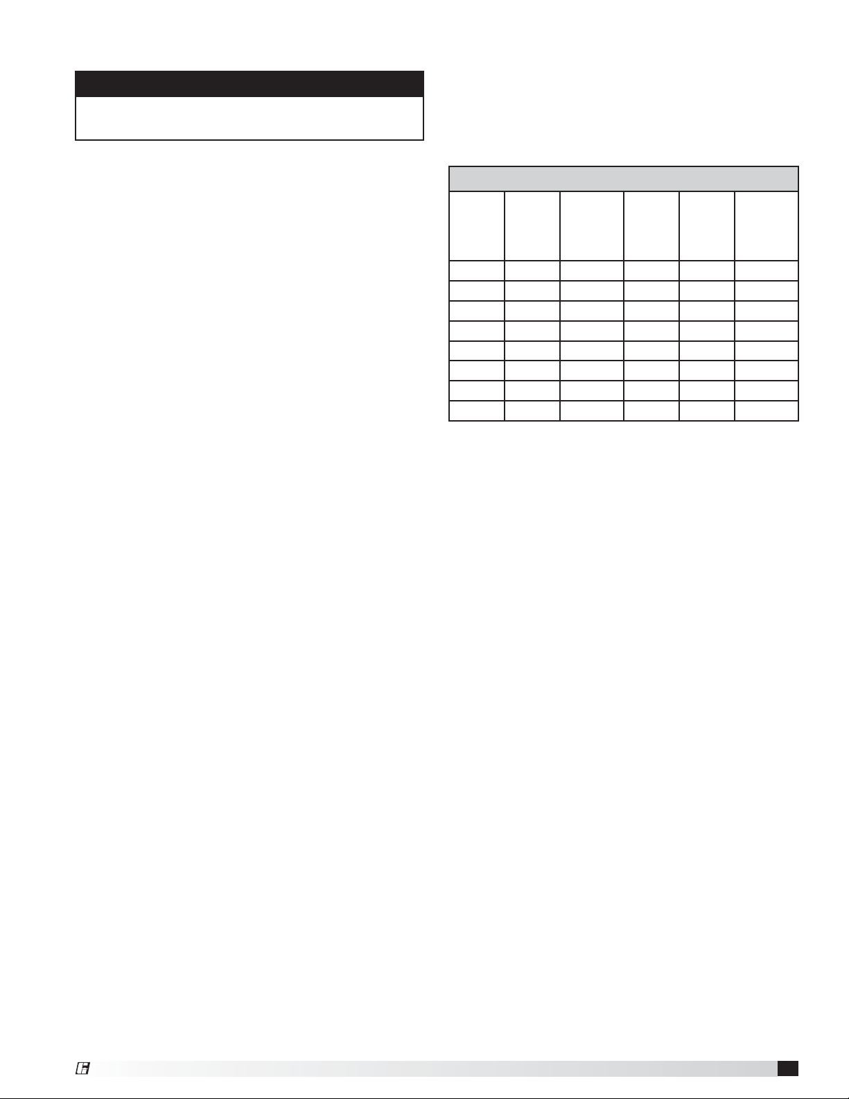
Effect of Low Voltage on Wattage and
British Thermal Unit (BTU)
The heating elements may be used on voltages
lower than the design voltage of the heater, however,
the wattage and BTU output will be reduced to the
percentages listed in the table below.
Installation of Electric Heater
(optional)
The requirements and practices described below
are based on the National Electric Code (NEC) and
The Space Heating Standard of the Underwriters
Laboratories Inc. (UL). Although UL requirements
are uniform throughout the country, local electrical
codes may deviate from the National Electrical Code.
Therefore, local inspection authorities should be
consulted regarding local requirements.
Electrical Wiring Instructions
1. Use the wiring diagram supplied with the heater as
a guide in correlating field wiring with the heater
internal wiring.
2. All field wiring to the heater must meet the
requirements of the National Electric Code and any
other applicable local or state codes.
3. Wiring to the heater must be rated for 75°C (167°F)
minimum.
4. The fan is interlocked by the factory to the control
circuit so the electric heater will not operate unless
the fan is on.
5. If heater does not have a built-in disconnect switch
or main circuit breaker, install a remote disconnect
(furnished by others) in accordance with the National
Electric Code, Article 424-65.
Derated Wattage For Low Voltage
Heater
Voltage
Line
Voltage
% of
Heater
Wattage
and BTU
Heater
Voltage
Line
Voltage
% of
Heater
Wattage
and BTU
480 460 92 208 200 92
440 84 190 83
277 265 92 120 115 92
254 84 110 84
240 230 92
220 84
208 75
200 69
10
Modular Supply Make-Up Air Unit
®
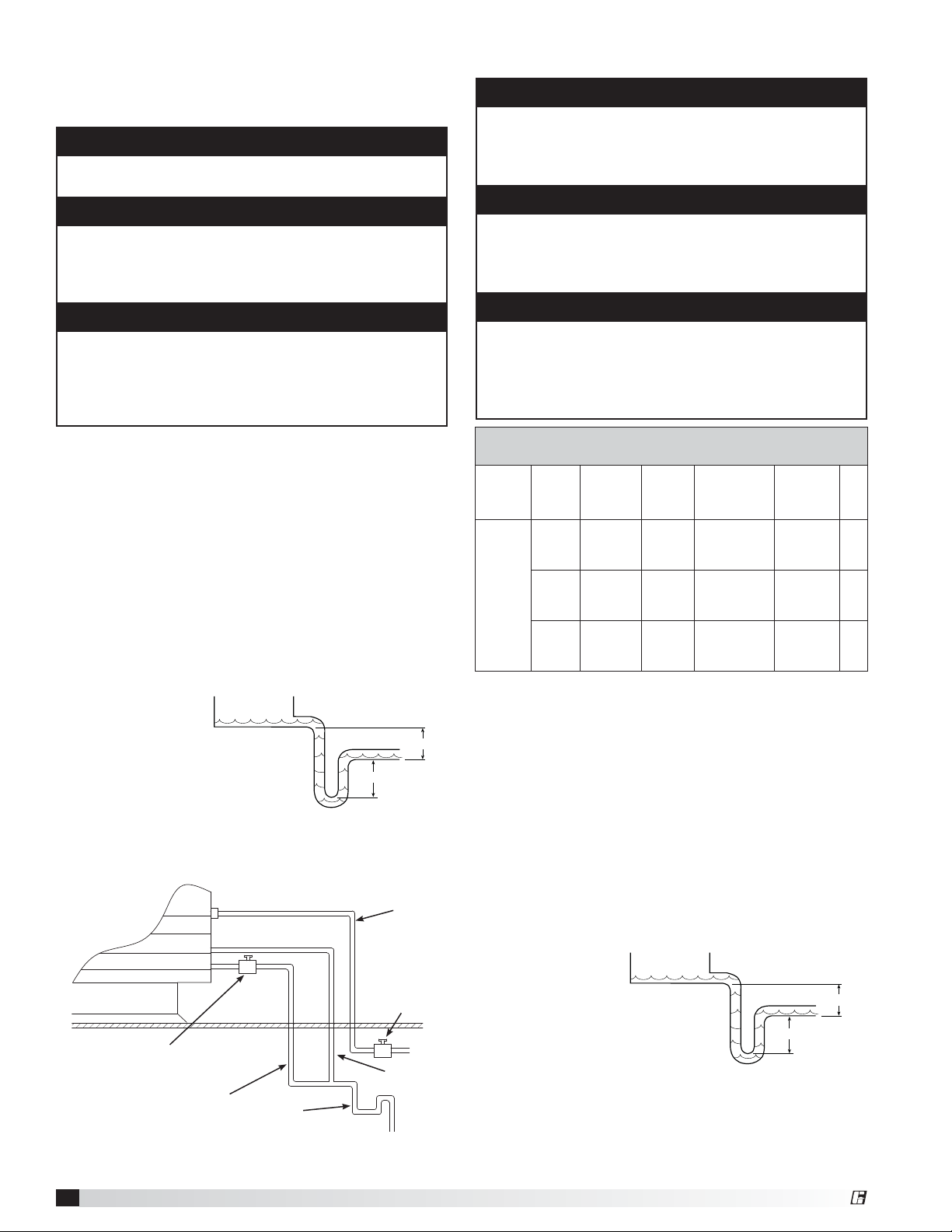
Installation Evaporative Cooler Piping
(optional)
Recirculating Evaporative Piping
IMPORTANT
All supply solenoids, valves and all traps must be below
the roof line or be otherwise protected from freezing.
IMPORTANT
The supply line should be of adequate size and
pressure to resupply the amount of water lost due to
bleed-off and evaporation. The drain line should be
the same size or larger than the supply line.
CAUTION
Provisions must be taken to prevent damage to the
evaporative cooling section during freezing conditions.
The sump, drain lines and supply lines must be drained
prior to freezing conditions or an alternate method must
be used to protect the lines and media.
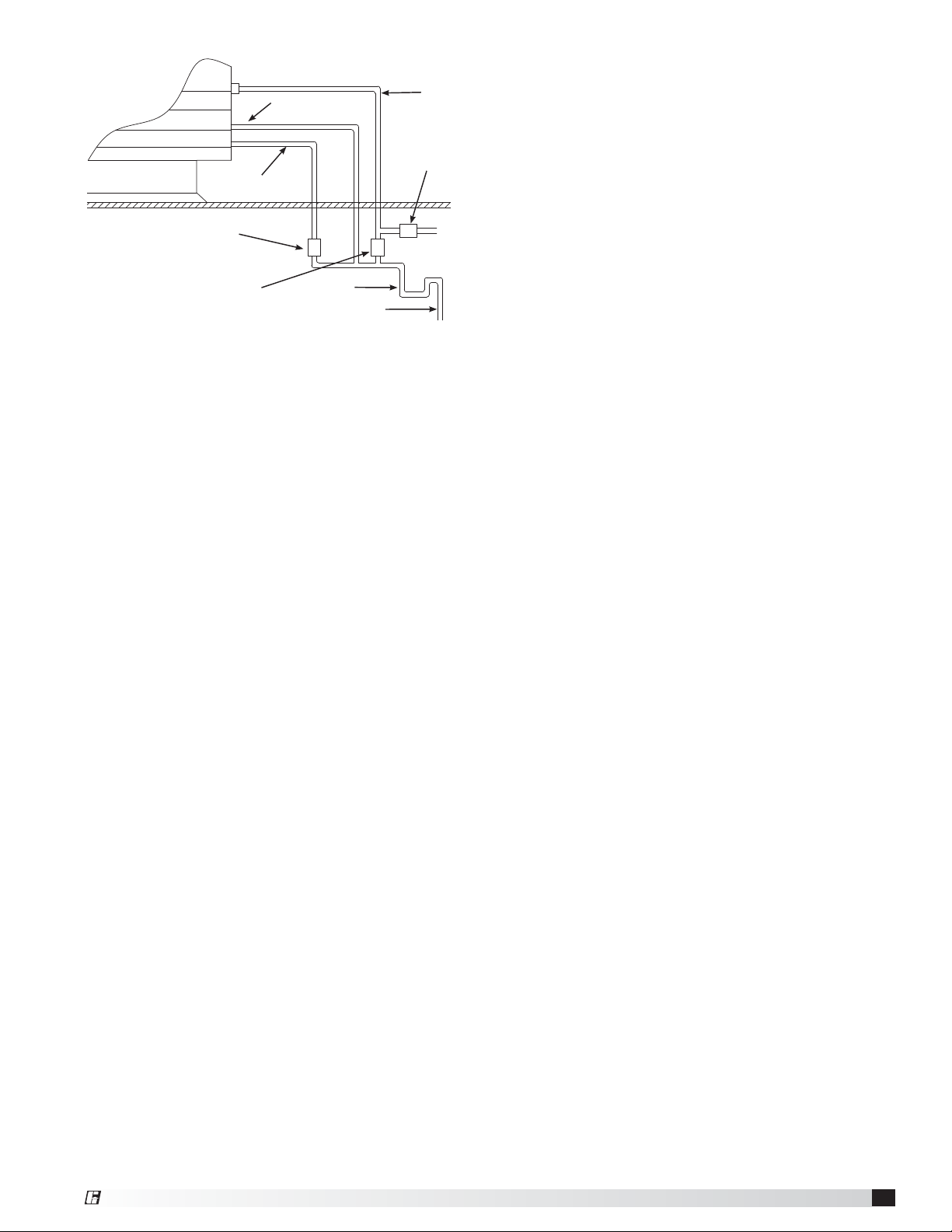
Evaporative Cooling with Recirculating Pump
1. Install the Water Supply Line. Supply line opening
requirements vary by unit size and arrangement and
are field supplied. Connect the water supply line to
the float valve through the supply line opening in
the evaporative cooling unit. Install a manual shutoff
valve in the supply line as shown.
2. Install the Drain Line. Connect an unobstructed
drain line to the drain and overflow connections on
the evaporative cooler. A manual shut off valve (by
others) is required for the evaporative cooler drain
line.
A trap should be used to prevent sewer gas from
being drawn into
the unit.
3. Check/Adjust
Water Level.
Check the water
level in the sump
tank. The water
level should be
above the pump
intake and below the overflow. Adjust the float as
needed to achieve the proper water level.
Supply
Line
Overflow
Trap
Drain Line Valve
(By Others)
Drain Line
Supply Line
Valve
(By Others)
6 in. min.
6 in. min.
Drain Trap
Auto Drain & Flush Valves
(When provided by Manufacturer)
Assembly
Number
Mfg
Part
Number
ASCO
Part
Number
Solenoid
Type
De-Energized
Position
Diameter
Qty.
852178
461262 8210G2
Supply Closed
1/2 inch
(12.7 mm)
1
461263 8262G262
Supply
Line
Drain
Open
1/4 inch
(6.35 mm)
1
461264 8210G35
Sump
Drain
Open
3/4 inch
(19.05 mm)
1
Part numbers subject to change.
IMPORTANT
The supply line should be of adequate size and
pressure to resupply the amount of water lost due to
bleed-off and evaporation. The drain line should be
the same size or larger than the supply line.
CAUTION
All solenoids valves and traps must be installed below the
roof to protect the supply water line from freezing. If they
cannot be installed below the roof, an alternative method
must be used to protect the lines from freezing.
IMPORTANT
The supply solenoid (Valve A) is NOT the same as the
drain solenoids (Valve B and Valve C). Make sure to
use the proper solenoid for each location. Check your
local code requirements for proper installation of this
type of system.
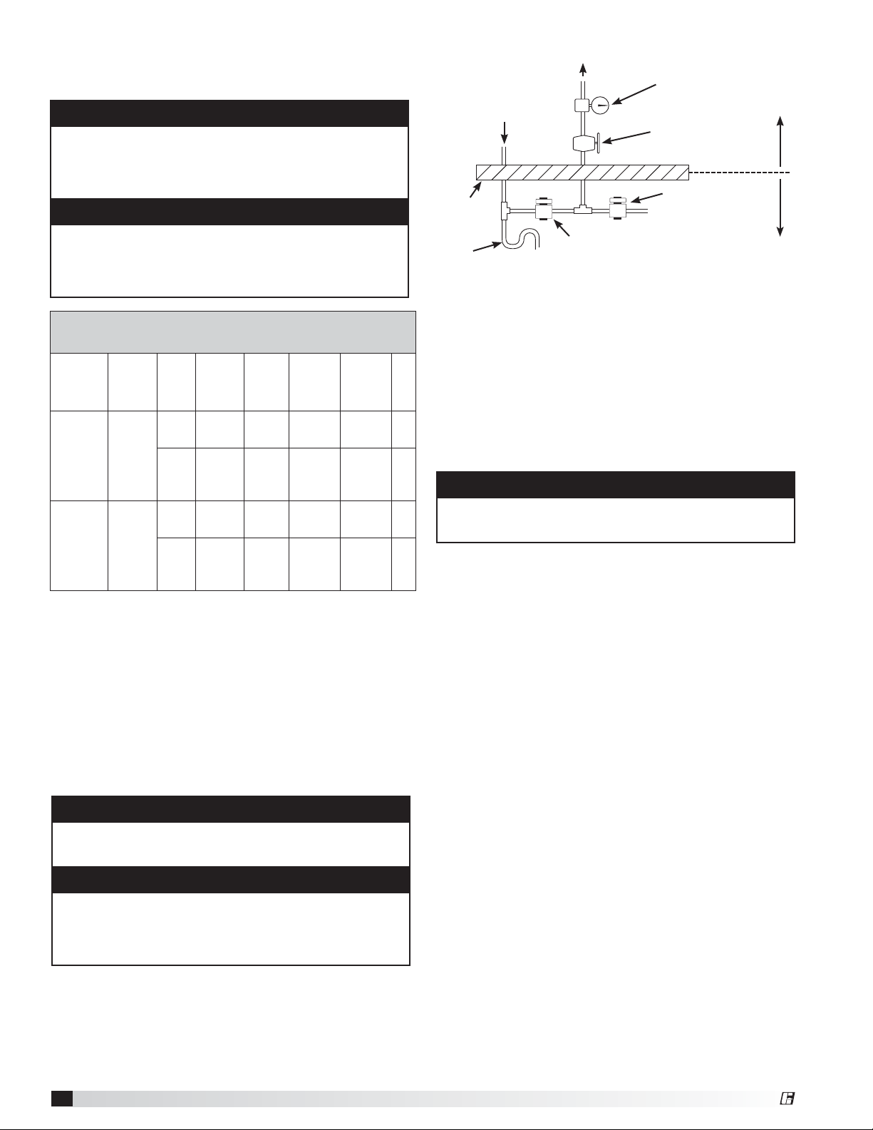
Auto Drain & Fill Evaporative Piping
1. Install the Water Supply Line. Supply line opening
requirements vary by unit size and arrangement and
are field supplied. Connect the water supply line to
the float valve through the supply line opening in the
evaporative cooling unit. Install the 1/2 in. normally
closed solenoid (Valve A) in the supply line. Install the
1/4 in. normally open solenoid (Valve B) between the
supply line and the drain line. Refer to Auto Drain &
Fill Evaporative Piping drawing on previous page.
2. Install the Drain Line. Connect an unobstructed
drain line to the sump drain overflow connection.
Install the 3/4 in. normally open solenoid (Valve C)
between the
sump drain
connection and
the drain line. A
trap should be
used to prevent
sewer gas from
being drawn into the unit.
3. Check/Adjust Water Level. Check the water level
in the sump tank. The water level should be above
the pump intake and below the overflow. Adjust the
float as needed to achieve the proper water level.
6 in. min.
6 in. min.
Drain Trap
11
Modular Supply Make-Up Air Unit
®
Evaporative Cooling with Auto Drain and Fill
Supply
Line
VALVE B
Supply Line Drain Solenoid
(Normally Open)
Sump Overflow
Sump Drain
VALVE C
Sump Drain Solenoid
(Normally Open)
VALVE A
Supply Solenoid
(Normally Closed)
Drain Line
Trap
12
Modular Supply Make-Up Air Unit
®
Installation of Water Wizard
TM
(optional)
Evaporative Cooling with the Water Wizard™
1. Install Normally Closed Supply Line/Solenoid.
Connect the water supply line to the manual supply
valve in the unit. Install the supply solenoid in the
supply line, upstream of the manual supply valve and
below the roof line.
2. Install Normally Open Drain Line/Solenoid.
Connect the drain line to the supply line between the
manual supply valve and the supply solenoid. Install
a drain solenoid in the drain line, below the roof line.
A trap should be installed in the drain line.
3. Wire the Solenoid(s). Wire the supply line solenoid
and drain solenoid as shown on the unit’s wiring
diagram in the control center.
4. Wire the Temperature Sensor. If the evaporative
cooler shipped separate from the unit, the
temperature sensor must be wired. The sensor
wire is bundled inside the discharge end of the
evaporative cooler. Wire the sensor wire to terminals
as shown on the unit’s wiring diagram.
NOTE
The following instructions are provided for evaporative
coolers equipped with the Water Wizard™ only.
Additional instructions are provided for evaporative
coolers equipped with the auto-drain and fill or bleed-off.
WARNING
Disconnect and lock-out all power and gas before
performing any maintenance or service to the unit.
Failure to do so could result in serious injury or death
and damage to equipment.
NOTE
Solenoid(s) may be provided by Manufacturer (if
ordered) or by others.
CAUTION
Any wiring deviations may result in personal injury or
property damage. Manufacturer is not responsible
for any damage to, or failure of the unit caused by
incorrect final wiring.
NOTE
The Water Wizard™ start-up must be completed for
proper performance.
Water Wizard™ Valves
(When provided by Manufacturer)
Unit
Model
Assembly
Number
Mfg.
Part
No.
ASCO
Part No.
Solenoid
Type
De-
Energized
Position
Diameter Qty.
MSX -
H12/H22
MSX - H32
(<9000 cfm)
852370
461262 8210G2
Supply Closed
1/2 inch
(12.7 mm)
1
383086 8210G34
Supply
Line
Drain
Open
1/2 inch
(12.7 mm)
1
MSX - H32
(≥9000 cfm)
MSX-H35,
H38, H42
852371
383088 8210G9
Supply Closed
3/4 inch
(19.05 mm)
1
383086 8210G34
Supply
Line
Drain
Open
1/2 inch
(12.7 mm)
1
Part numbers subject to change.
Water Wizard™ Installation
Supply Line Drain Solenoid
(Normally Open)
Supply Solenoid
(Normally Closed)
Manual Supply
Valve
Pressure
Gauge
To Media
Sump Drain
Roof
Line
Trap
Field
Installed
Factory
Installed
 Loading...