


Centrifugal Cabinet Fans
Model BCF
Belt Drive Low-Profile
May
2007
BCF
Belt Drive Cabinet Fans
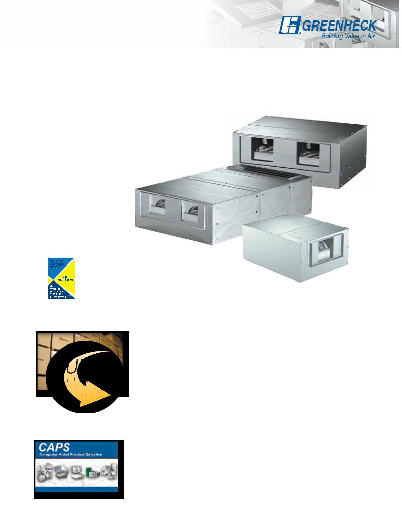
Greenheck belt drive low-profile cabinet fans, Model BCF, are designed for efficiency and reliability in supply, exhaust or ducted return applications. Featuring a compact, rectangular cabinet design, they mount easily in standard duct passages. Horizontal mounting with either top horizontal or upblast discharge allows the BCF to be applied in a wide range of air handling applications.
BCF cabinet fans are available in single and double fan models. Both feature the combination of a quiet running, forward curved wheel and a well proportioned fan housing efficiency. In double fan models, each wheel is housed separately, but both are driven by a single motor and shaft. Fan wheels are statically and dynamically balanced to assure vibration free operation.
•Every model has been designed with low-profile construction to fit within tight spaces, as low as 11 inches (280 mm).
•Capacities range from 170 to 5,850 cfm (290 to
9950 m3/hr.) with static pressures up to 1½ in. wg (375 Pa).
•All fan sizes are tested in our AMCA Accredited Laboratory, and all BCF sizes are
licensed to bear the AMCA certified rating seal for air performance.
•Greenheck subjects these products to extensive life testing assuring you that the fans will provide years of reliable performance.
Greenheck Fan Corporation certifies that the model BCF fans shown herein are licensed to bear the AMCA Seal. The ratings shown are based on tests and procedures performed in accordance with AMCA Publication 211 and comply with the requirements of the AMCA Certified Ratings Program. The certified ratings for Model BCF are shown on pages 6 to 15.
Quick Delivery and Quick Build Programs
All BCF sizes are available through our five and ten day Quick Build (QB) program. This allows the flexibility of knowing that your fan can be made to order and shipped in as little as five days.
Many products are available from our Quick Delivery (QD) program. The QD program provides same day shipment of Greenheck product from our
strategically located warehouses throughout the world. These stock products can be ordered over the internet by visiting www.greenheck.com/quick
Leading Edge Technical Support
When product and IOM (Installation, Operation and Maintenance Manual) information is needed, our products are supported by the industry’s best product literature, electronic media, and Computer Aided Product Selection (CAPS) program. You’ll also find this information on our website at www.greenheck.com
Our national and international representative organization provides outstanding personal service and expertise. To locate your nearest Greenheck representative,
call 715-359-6171 or visit our website at www.greenheck.com
2
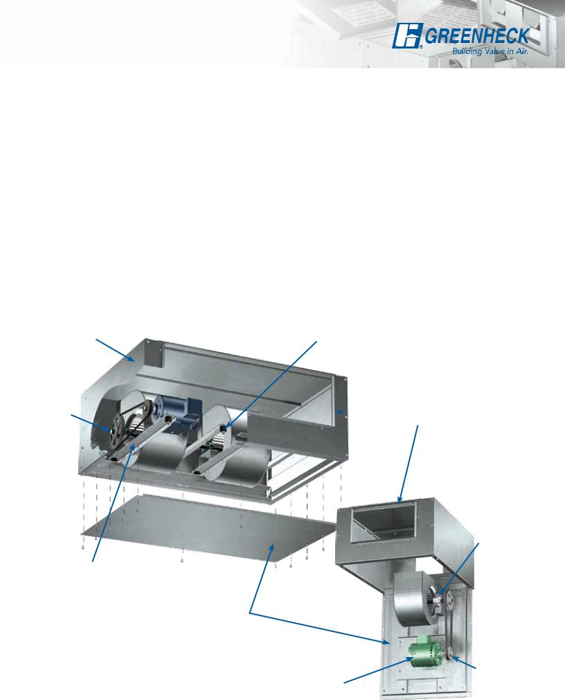
Standard Construction Features
Vibration Isolation - Internal true vibration isolators support the entire drive assembly, wheel, and scroll without steel to steel contact. This provides long life and quiet operation.
Housing - The fan cabinet is constructed of galvanized steel for corrosion resistance and maintenance free operation.
Access Panel - Hinged or removable panels allow for easy access to all internal components. Hinged panels are on fan sizes 106, 107, 206 and 207 and are removable on the larger sizes in both single and double fans.
Bearings - Permanently sealed, pillow block ball bearings are selected for a minimum L10 life in excess of 100,000 hours (L50 average life of 500,000 hours) at maximum catalogued operating conditions.
Wheel - Forward curved, centrifugal, galvanized steel wheel is utilized to generate high efficiency and minimal sound. Each wheel is statically and
dynamically balanced for long life and quiet operation.
Housing
Fan
Shaft
Drive Frame
Access Panel
Motor - Ball bearing motors are carefully matched to the fan load. Open drip proof and totally enclosed enclosures are available.
Drive Frame - Constructed from heavy gauge steel and designed with belt adjustment to eliminate scroll damage. Adjustment is accomplished by loosening fasteners, sliding motor plate, and retightening.
Drive Assembly - Belts, pulleys and keys are sized for a minimum of 150% of driven horsepower. Machined cast iron pulleys are factory set to the required RPM and adjustable for final system balancing. Belts are static free and oil resistant.
Fan Shaft - Precisely sized, ground, and polished so the first critical speed is at least 25% over the maximum operating speed. With the shaft making contact with bearings, close tolerances result in longer bearing life.
Duct Collars - Inlet and outlet duct collars are provided for easy duct connections.
Vibration Isolation
 Duct Collars
Bearings
 Wheel
Wheel
|
Drive |
Motor |
Assembly |
3
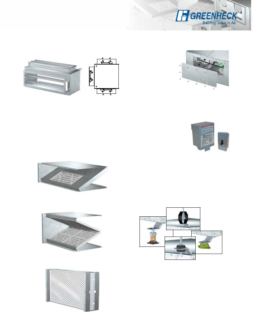
Options and Accessories
Mixing Boxes - Constructed of galvanized steel and available with or without dampers. Inlet position must be specified. Any two of the three positions shown (X, Y or Z) may be selected.
X
Y
Z
Filter Boxes - Constructed of galvanized steel. Available with either a sloped filter arrangement or vertical slide-out. Smaller fan sizes (106, 107, 206 and 207) have a sloped single angled filter. The doublevee configuration is used with all larger sloped sizes. Filters are available in 1 or 2-inch disposable media or permanent, washable aluminum mesh. Filter boxes with slide-out have 2-inch washable aluminum filters.
Sloped, Single Angled Filter - Sizes 106, 107, 206 and 207
Sloped, Double-Vee Filter - Sizes 108, 110, 112, 208, 210 and 212
Slide-Out, Aluminum Filter - Sizes 106 thru 212
Side Access Doors - For installations where normal access is restricted, removable side access doors are available for ease of inspecting and servicing fan wheels, motors, belts and drives. Door locations must be specified left or
right as viewed from the discharge end of the fan. Surrounding ductwork or other equipment should be considered when selecting the access door location.
Insulated Housing - For noise reduction and condensation control, the interior of fan housings, mixing box and filter box can be lined with a fiberglass duct liner (1/2 or 1-inch insulation
are available).
Disconnect Switches - A wide selection of NEMA rated switches are available for positive electrical shutoff and safety. This includes general, dust-tight, rainproof, and corrosion-resistant.
Vibration Isolators - Base and hanging isolator kits are available with either neoprene or spring isolators. Kits range in size to support either the weight of
the fan alone or the weight of the fan with filter and mixing box combinations. Kits are for horizontal mounting and include mounting brackets and hardware. Knockouts are provided in the fan cabinet for ease of installation. (Hanging rods supplied by others.)
Hanging Spring
Neoprene
Standing
Spring
Hanging Neoprene
Wiring Pigtail - Allows direct hook-up to the power supply externally (eliminating field wiring at the fan).
Coatings - A wide variety of protective or decorative coatings are available. Consult Greenheck’s Performance Coatings for Commercial & Industrial Fans brochure and our Product Application Guide FA/110-04R, Performance Coatings for Ventilation Products, for in-depth information.
4
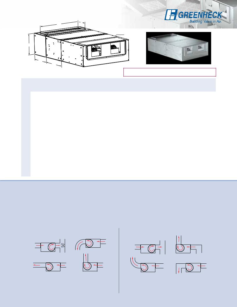
Filter and Mixing Box Data
 D
D
C
 Mixing Box
 Filter Box
Fan
B
B
A
All dimensions in inches (millimeters). Weight in pounds (kilograms).
NOTE: Kilogram weights have been corrected use this posted copy for corrected weights. Printed edition is incorrect. (R.7-13-10)
BCF |
|
A |
|
|
|
Filter Box Weight lb. (kg) |
|
Filter Size |
|
Mixing Box Weight lb. (kg) |
||||
|
|
|
B |
C |
D |
|
|
|
|
|
|
|
|
|
Slide- |
|
Sloped |
Slide-Out |
Sloped |
Slide-Out |
Qty. |
Sloped |
Qty. |
Without |
With |
||||
Size |
Out |
|
|
|
|
Damper |
Damper |
|||||||
|
|
|
|
|
|
|
|
|
|
|
|
|||
106 |
6 |
|
22 |
11 |
12 |
6 |
9 |
24 |
191 x 101/4 |
1 |
16 x 20 |
1 |
14 |
29 |
(152) |
|
(559) |
(279) |
(305) |
(152) |
(4.1) |
(10.9) |
(495 x 260) |
(406 x 508) |
(6.4) |
(13.2) |
|||
|
|
|
|
|||||||||||
|
|
|
|
|
|
|
|
|
|
|
|
|
|
|
107 |
6 |
|
23 |
13 |
15 |
8 |
10 |
26 |
227/8 x 121/4 |
1 |
16 x 20 |
1 |
17 |
36 |
(152) |
|
(584) |
(330) |
(381) |
(203) |
(4.5) |
(11.8) |
(581 x 311) |
(406 x 508) |
(7.7) |
(16.3) |
|||
|
|
|
|
|||||||||||
108 |
6 |
|
24 |
16 |
18 |
10 |
12 |
39 |
257/8 x 151 |
1 |
16 x 20 |
2 |
23 |
45 |
(152) |
|
(610) |
(406) |
(457) |
(254) |
(5.4) |
(17.7) |
(657 x 394) |
(406 x 508) |
(10.4) |
(20.4) |
|||
|
|
|
|
|||||||||||
110 |
7 |
|
25 |
19 |
24 |
12 |
20 |
64 |
317/8 x 181 |
1 |
20 x 20 |
2 |
40 |
69 |
(178) |
|
(635) |
(483) |
(610) |
(305) |
(9.1) |
(29) |
(810 x 470) |
(508 x 508) |
(18.1) |
(31.3) |
|||
|
|
|
|
|||||||||||
112 |
7 |
|
27 |
23 |
28 |
14 |
28 |
86 |
357/8 x 223/8 |
1 |
16 x 20 |
4 |
64 |
100 |
(178) |
|
(686) |
(584) |
(711) |
(356) |
(12.7) |
(39) |
(911 x 568) |
(406 x 508) |
(29) |
(45.4) |
|||
|
|
|
|
|||||||||||
206 |
6 |
|
22 |
11 |
26 |
6 |
12 |
35 |
337/8 x 101/4 |
1 |
20 x 20 |
1 |
19 |
42 |
(152) |
|
(559) |
(279) |
(660) |
(152) |
(5.4) |
(15.9) |
(860 x 260) |
(508 x 508) |
(8.6) |
(19.1) |
|||
|
|
|
|
|||||||||||
207 |
6 |
|
23 |
13 |
30 |
8 |
14 |
36 |
377/8 x 121/4 |
1 |
16 x 20 |
2 |
23 |
52 |
(152) |
|
(584) |
(330) |
(762) |
(203) |
(6.4) |
(16.3) |
(962 x 311) |
(406 x 508) |
(10.4) |
(23.6) |
|||
|
|
|
|
|||||||||||
208 |
6 |
|
24 |
16 |
36 |
10 |
17 |
50 |
437/8 x 151 |
1 |
16 x 20 |
4 |
31 |
67 |
(152) |
|
(610) |
(406) |
(914) |
(254) |
(7.7) |
(22.7) |
(1114 x 394) |
(406 x 508) |
(14.1) |
(30.4) |
|||
|
|
|
|
|||||||||||
210 |
7 |
|
25 |
19 |
40 |
12 |
26 |
79 |
477/8 x 181 |
1 |
20 x 20 |
4 |
51 |
93 |
(178) |
|
(635) |
(483) |
(1016) |
(305) |
(11.8) |
(35.8) |
(1216 x 470) |
(508 x 508) |
(23.1) |
(42.2) |
|||
|
|
|
|
|||||||||||
212 |
7 |
|
27 |
23 |
50 |
14 |
38 |
119 |
577/8 x 221 |
1 |
20 x 25 |
4 |
86 |
142 |
(178) |
|
(686) |
(584) |
(1270) |
(356) |
(17.2) |
(54) |
(1470 x 572) |
(508 x 635) |
(39) |
(64.4) |
|||
|
|
|
|
|||||||||||
Typical Installations
Model BCF fans are available with either top horizontal or upblast discharge positions. To select the most effective fan position and discharge, it is necessary to consider the direction of air entering the fan and the direction of exhausted air. All of the accessories shown on page four can be used with the installations shown.
In order to assure proper fan performance, caution must be exercised in fan placement and connection. Obstructions, transitions, poorly designed elbows, etc., can cause reduced performance, excessive noise, and increase mechanical stress. For performance to be as published, the system must provide uniform and stable airflow into the fan.
Good |
Poor |
Airflow should discharge in the same direction as the wheel rotation. Provide uniform airflow to the fan inlet. Use turning vanes in elbows to reduce adverse effects where needed.
Do not install fans with ductwork directing airflow in the opposite direction of wheel rotations. Avoid sharp turns, poorly designed elbows, and
transitions which cause uneven airflow.
5
 Loading...