


ESU-130
Thin-line Louver
Thin-line Blade
Application and Design
ESU-130 is a thin-line stationary louver commonly used for interior or exterior applications where high free area and low airflow resistance is required. The narrow depth makes this product ideal for installation into curtainwalls, windows, doors, or as air conditioning grilles.
Standard Construction
Frame . . . . . . . .Heavy gauge extruded 6063T5 aluminum, 1 ½ in. x 0.063 in. nominal wall thickness
Blades . . . . . . . .Thin-line style, heavy gauge extruded 6063T5 aluminum, 0.063 in. nominal wall thickness, positioned at 30º angles on approximately ¾ in. centers
Birdscreen. . . . .3/4 in. x 0.051 fl attened expanded aluminum in removable frame, inside mount (rear)
Finish. . . . . . . . .Mill
Minimum Size . .13.5 in. W x 10 in. H (without fl ange) 13.5 in. W x 12 in. H (with fl ange)
Maximum Single
Section Size . . .96 in. W x 48 in. H
Options (at additional cost)
• A variety of bird and insect screens
• Anchor brackets
• Captivated frame
• Extended sill
• Flanged frame
• Glazing adaptor
• A variety of architectural finishes including: Clear anodize
Integral color anodize Baked enamel paint Kynar paint
*Width and height dimensions furnished approximately ¼ inch under size.
PERFORMANCE DATA |
|
|
|
|
|
|
|
|
ESU-130 |
||||||||
|
|
|
|
|
|
|
|
|
|
|
|
|
|
|
|
|
Thin-line Louver |
|
|
|
|
|
|
|
|
|
|
|
|
|
|
|
|
|
Extruded Aluminum |
Free Area Chart (Sq. ft.) |
|
|
|
|
|
|
|
|
|
|
|
|
|||||
Louver |
|
|
|
|
|
|
Louver Width in Inches |
|
|
|
|
|
|
||||
Height |
|
|
|
|
|
|
|
48 |
|
|
|
|
|
|
|
|
|
Inches |
10 |
12 |
18 |
24 |
30 |
36 |
42 |
54 |
60 |
66 |
72 |
78 |
84 |
90 |
96 |
|
|
|
|
|
|
|
|
|
|
|
|
|
|
|
|
|
|
|
|
10 |
0.27 |
0.36 |
0.62 |
0.90 |
1.18 |
1.46 |
1.74 |
2.03 |
2.22 |
2.50 |
2.79 |
3.07 |
3.35 |
3.55 |
3.83 |
4.11 |
|
|
|
|
|
|
|
|
|
|
|
|
|
|
|
|
|
|
|
12 |
0.33 |
0.44 |
0.76 |
1.11 |
1.46 |
1.80 |
2.15 |
2.50 |
2.74 |
3.09 |
3.43 |
3.78 |
4.12 |
4.37 |
4.71 |
5.06 |
|
|
|
|
|
|
|
|
|
|
|
|
|
|
|
|
|
|
|
15 |
0.42 |
0.57 |
0.98 |
1.42 |
1.87 |
2.31 |
2.76 |
3.20 |
3.51 |
3.96 |
4.40 |
4.84 |
5.29 |
5.60 |
6.05 |
6.49 |
|
|
|
|
|
|
|
|
|
|
|
|
|
|
|
|
|
|
|
18 |
0.51 |
0.70 |
1.20 |
1.74 |
2.28 |
2.82 |
3.36 |
3.90 |
4.29 |
4.83 |
5.37 |
5.91 |
6.45 |
6.84 |
7.38 |
7.92 |
|
|
|
|
|
|
|
|
|
|
|
|
|
|
|
|
|
|
|
21 |
0.61 |
0.82 |
1.41 |
2.05 |
2.69 |
3.33 |
3.97 |
4.61 |
5.06 |
5.70 |
6.34 |
6.98 |
7.62 |
8.07 |
8.71 |
9.35 |
|
|
|
|
|
|
|
|
|
|
|
|
|
|
|
|
|
|
|
24 |
0.70 |
0.95 |
1.63 |
2.36 |
3.10 |
3.84 |
4.57 |
5.31 |
5.83 |
6.57 |
7.31 |
8.04 |
8.78 |
9.30 |
10.04 |
10.78 |
|
|
|
|
|
|
|
|
|
|
|
|
|
|
|
|
|
|
|
27 |
0.79 |
1.07 |
1.84 |
2.68 |
3.51 |
4.35 |
5.18 |
6.01 |
6.61 |
7.44 |
8.27 |
9.11 |
9.95 |
10.54 |
11.37 |
12.20 |
|
|
|
|
|
|
|
|
|
|
|
|
|
|
|
|
|
|
|
30 |
0.89 |
1.20 |
2.06 |
2.99 |
3.92 |
4.85 |
5.79 |
6.72 |
7.38 |
8.31 |
9.24 |
10.18 |
11.11 |
11.77 |
12.70 |
13.63 |
|
|
|
|
|
|
|
|
|
|
|
|
|
|
|
|
|
|
|
33 |
0.98 |
1.32 |
2.27 |
3.31 |
4.33 |
5.36 |
6.39 |
7.43 |
8.15 |
9.18 |
10.21 |
11.24 |
12.27 |
13.00 |
14.03 |
15.06 |
|
|
|
|
|
|
|
|
|
|
|
|
|
|
|
|
|
|
|
36 |
1.07 |
1.45 |
2.49 |
3.62 |
4.74 |
5.87 |
7.00 |
8.13 |
8.93 |
10.05 |
11.18 |
12.31 |
13.44 |
14.24 |
15.36 |
16.49 |
|
|
|
|
|
|
|
|
|
|
|
|
|
|
|
|
|
|
|
39 |
1.13 |
1.57 |
2.70 |
3.93 |
5.15 |
6.38 |
7.61 |
8.83 |
9.70 |
10.92 |
12.15 |
13.38 |
14.60 |
15.47 |
16.69 |
17.92 |
|
|
|
|
|
|
|
|
|
|
|
|
|
|
|
|
|
|
|
42 |
1.26 |
1.70 |
2.92 |
4.25 |
5.56 |
6.89 |
8.21 |
9.54 |
10.47 |
11.79 |
13.12 |
14.44 |
15.77 |
16.70 |
18.02 |
19.35 |
|
|
|
|
|
|
|
|
|
|
|
|
|
|
|
|
|
|
|
45 |
1.35 |
1.82 |
3.14 |
4.56 |
5.97 |
7.40 |
8.82 |
10.24 |
11.25 |
12.66 |
14.09 |
15.51 |
16.93 |
17.92 |
19.35 |
20.77 |
|
|
|
|
|
|
|
|
|
|
|
|
|
|
|
|
|
|
|
48 |
1.44 |
1.95 |
3.35 |
4.87 |
6.39 |
7.91 |
9.43 |
10.95 |
12.02 |
13.53 |
15.05 |
16.58 |
18.10 |
19.17 |
20.68 |
22.20 |
|
|
|
|
|
|
|
|
|
|
|
|
|
|
|
|
|
|
|
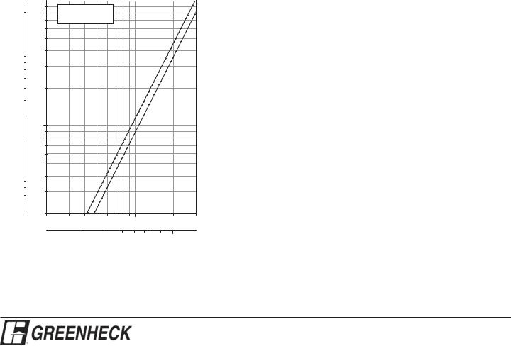
Airflow Resistance (Standard Air - .075 lb/ft3)
Static Pressure Drop
Pa |
in. wg |
|
1 |
|
0.9 |
2000.8
0.7
0.6
0.5
100 |
|
0.4 |
|
|
|||
90 |
|
|
|
80 |
0.3 |
||
70 |
|||
|
|
||
60 |
|
|
|
50 |
0.2 |
||
40 |
|
|
|
30 |
|
|
|
|
0.1 |
||
|
0.09 |
||
200.08
0.07
0.06
0.05
10 |
|
0.04 |
|
|
|||
9 |
|
|
|
8 |
0.03 |
||
7 |
|||
|
|
||
6 |
|
|
|
5 |
0.02 |
||
ft/min: 200
Test Size 48 in. x 48 in.
3
Standard Air - .075 lb/ft
Intake |
Exhaust |
300 |
400 |
500 |
600 700 800 9001000 |
2000 |
3000 |
This half intentionally left blank.
m/s: |
2 |
3 |
4 |
5 |
6 |
7 |
8 |
9 10 |
Free Air Velocity
Model ESU-130 resistance to airflow (pressure drop) varies depending on louver application (air intake or air exhaust). Free area velocities (shown) are higher than average velocity through the overall louver size. See louver selection information.
 Loading...