


Tubular Centrifugal Fans
Model TCB
Inline - Horizontal or Vertical
Roof Upblast and Roof Supply
March
2007

Tubular Centrifugal Fans
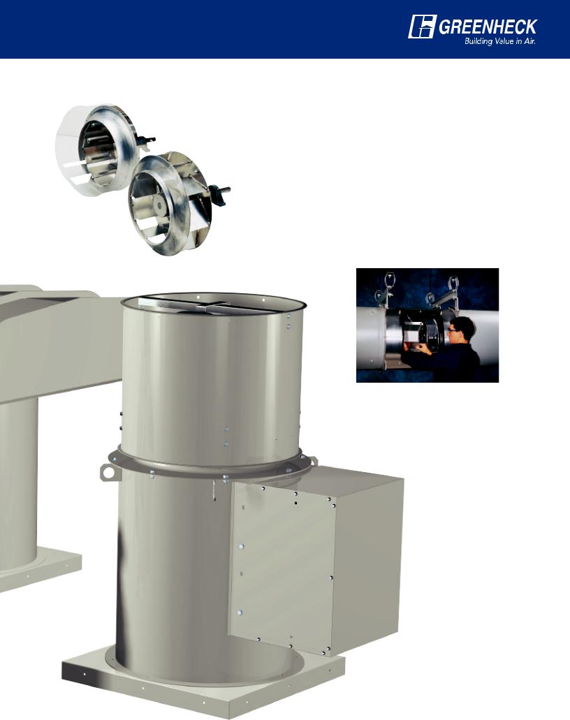
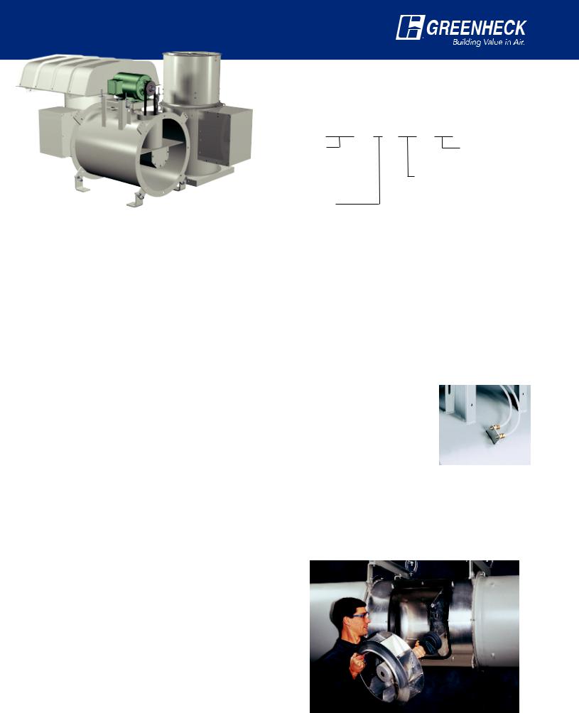
The TCB series of inline centrifugal fans is designed for ducted inline, roof upblast, and roof supply installations. Whether the application is commercial or industrial, Greenheck tubular centrifugal fans provide quiet, efficient, and reliable air performance.
All TCB products are belt driven with motors out of the airstream. Housings are constructed of welded steel or aluminum (optional) and are suitable for indoor or outdoor applications. The backward inclined wheels are
manufactured from aluminum and are suitable for clean air or fume exhaust applications. All TCB products meet “Type B” construction as defined by AMCA Standard 99-0401 Classification for Spark Resistant Construction. In addition, the TCB is available with the UL 762 listing for restaurant exhaust applications.
Greenheck Fan Corporation certifies that the model TCB tubular centrifugal inline fans shown herein are licensed to bear the AMCA seal. The ratings
shown are based on tests and procedures performed in accordance with AMCA Publication 211 and Publication 311 and comply with the requirements of the AMCA Certified Ratings Program.
Model TCB is available with the UL 762 Listing (Power Ventilators for Restaurant Exhaust Appliances).
Models TCB, TCBRU, and TCBRS are Listed for electrical (UL/cUL 705). File no. E40001
Model TCB — Inline Fan
•Sizes from 09 to 36
•Performance Range: 360 to 24,000 cfm (610 - 40,750 m³/hr)
•Static Pressure: Up to 4.5 in. wg (1,125 Pa)
•Max Operating Temperature: 200°F (90°C)
•Horizontal or Vertical Mounting
•Options: — Easy Access
—All Aluminum Construction
—UL 762 for Restaurant Exhaust
Model TCBRS —
Roof Supply Fan
• Sizes from 09 to 36
• Performance Range: 360 to 24000 cfm (610 - 40,750 m³/hr)
• Static Pressure: Up to 4 in. wg (1,000 Pa)
• Max Operating Temperature: 200°F (90°C)
• Options: – Insect Screen or Filters
– Easy Access
– All Aluminum Construction
2
Two Levels of Construction
All TCB inline and roof mounted fans are available in two levels of construction to provide the most efficient and economical selections. Construction differences between level 1 and 2 selections include the impeller, the inlet cone, the shaft size, and the bearings. The housings for both levels are identical in material gauge and overall design.
Level 1 Construction
•Maximum pressure capabilities of 2 in. wg (500 Pa)
•Highest efficiencies at static pressures below 1.5 in. wg (375 Pa)
•Aluminum wheel construction
•Most economical selections
Level 2 Construction
•Maximum pressure capabilities of 4.5 in. wg (1,125 Pa)
•Highest efficiencies at static pressures above 1.5 in. wg (375 Pa)
•Completely welded aluminum wheel
•Increased shaft and bearing diameter
•Increased horsepower and motor frame size capability
Easy Access Feature
All models are available with an optional oversized access door for serviceability of fan components without removing the fan or duct. See page 8 for details.
Model TCBRU —
Roof Upblast Fan
• Sizes from 09 to 36
• Performance Range: 425 to 24,000 cfm (722 - 40,750 m³/hr)
• Static Pressure: Up to 4 in. wg (1,000 Pa)
• Max Operating Temperature: 200°F (90°C)
• Options: — Easy Access
— All Aluminum Construction
3

Construction Specifications
Hood Panels
Housing
Model TCB |
Housing |
Model TCBRU |
Curb Cap |
Model TCBRS |
|
||||
|
|
|
Steel Construction (gauge)
Size |
Housing |
Curb Cap |
Windband |
Hood |
Shaft Diameter (in.) |
||
Panels |
|
|
|||||
Level 1 |
Level 2 |
||||||
|
|
|
|
||||
|
|
|
|
|
|
|
|
09 |
12 |
12 |
20 |
22 |
3/4 |
1 |
|
10 |
12 |
12 |
20 |
22 |
3/4 |
1 |
|
12 |
12 |
12 |
20 |
22 |
3/4 |
1 |
|
13 |
12 |
12 |
20 |
22 |
3/4 |
1 |
|
16 |
12 |
12 |
20 |
22 |
1 |
1 3/16 |
|
18 |
12 |
12 |
20 |
22 |
1 |
1 3/16 |
|
22 |
10 |
12 |
20 |
22 |
1 |
1 7/16 |
|
24 |
10 |
12 |
20 |
22 |
1 |
1 11/16 |
|
30 |
10 |
12 |
20 |
22 |
11/4 |
1 15/16 |
|
36 |
10 |
12 |
20 |
22 |
11/2 |
1 15/16 |
|
Aluminum Construction (thickness in inches)
Size |
Housing |
Curb Cap |
Windband |
Hood |
Shaft Diameter (in.) |
||
Panels |
|
|
|||||
Level 1 |
Level 2 |
||||||
|
|
|
|
||||
|
|
|
|
|
|
|
|
09 |
0.125 |
0.125 |
0.051 |
0.051 |
3/4 |
1 |
|
10 |
0.125 |
0.125 |
0.051 |
0.051 |
3/4 |
1 |
|
12 |
0.125 |
0.125 |
0.051 |
0.051 |
3/4 |
1 |
|
13 |
0.125 |
0.125 |
0.051 |
0.051 |
3/4 |
1 |
|
16 |
0.125 |
0.125 |
0.051 |
0.051 |
1 |
1 3/16 |
|
18 |
0.125 |
0.125 |
0.051 |
0.051 |
1 |
1 3/16 |
|
22 |
0.125 |
0.125 |
0.051 |
0.051 |
1 |
1 7/16 |
|
24 |
0.125 |
0.125 |
0.051 |
0.051 |
1 |
1 11/16 |
|
30 |
0.19 |
0.125 |
0.051 |
0.051 |
11/4 |
1 15/16 |
|
36 |
0.19 |
0.125 |
0.051 |
0.051 |
11/2 |
1 15/16 |
|
4
TCB Inline Fan - Belt Drive
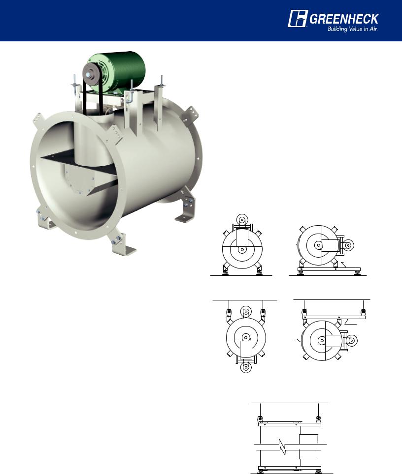
Universal Mounting
All TCB fans can be mounted horizontally or vertically. For ease of installation, eight mounting brackets are welded on each fan. The eight brackets along with four mounting supports, provide a universal mounting system.
Fig. 1 Horizontal Base Mount
Each fan is shipped as standard in this arrangement. Motor at 12 o’clock is standard.
Fig. 2 Horizontal Base Mount with Motor at 3 or 9 o’clock
A set of optional mounting rails are required for this installation. This is the base mounting position required with the easy access option.
Fig. 3 Horizontal Ceiling Hung
In this installation the supports can be positioned for mounting the motor at either 6 or 12 o’clock.
Fig. 4 Horizontal Ceiling Hung with Motor at 3 or 9 o’clock
A set of optional mounting rails are required for this installation.
Fig. 5 Vertical Mount
All TCB fans can be mounted vertically (ceiling hung or base mount) for either upward or downward airflow. Optional mounting rails are recommended.
NOTE:
All fans are shown with optional vibration isolators. See the appropriate submittal drawings or installation manual for complete dimensional data.
The Model TCB inline fan is the ideal choice for ducted systems. Greenheck’s standard fan can be mounted in any position from horizontal to vertical, allowing installation in the smallest possible space at the lowest installation cost. The centrifugal wheels used in this design provide higher efficiencies and lower sound levels than propeller type inline fans when used in medium pressure ducted systems. TCB fans are available in either painted steel or aluminum construction.
Typical applications include:
•General exhaust or supply
•Industrial space ventilation
•Fume hood exhaust (special coatings are available)
•Combustion air
•Roof exhaust or supply (with weatherhood)
•Restaurant grease exhaust
Easy
Access
Option 
Optional
Mounting Rails
Horizontal Base Mount |
Horizontal Base Mount |
Motor at 3 or 9 o'clock position |
|
Fig. 1 |
Fig. 2 |
Easy |
Optional |
Mounting Rails |
|
Access |
|
Option |
|
|
Horizontal Ceiling Hung |
Horizontal Ceiling Hung |
Motor at 3 or 9 o'clock position |
Fig. 3 |
Fig. 4 |
Vertical Ceiling Hung
Vertical Base Mount
Fig. 5
5
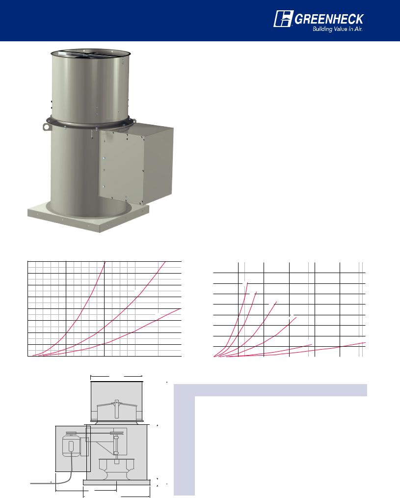
TCBRU Roof Upblast Fan
System Effect Curves
Sizes 9-13
|
0.8 |
|
|
|
|
0.7 |
|
|
10 |
|
|
|
09, |
|
|
0.6 |
|
|
|
(inches) |
|
|
|
|
0.5 |
|
|
|
|
Loss |
|
|
|
|
0.4 |
|
|
|
|
Pressure |
|
|
|
|
0.3 |
|
|
|
|
|
|
|
|
|
|
0.2 |
|
|
|
|
0.1 |
|
|
|
|
0.0 0 |
1 |
|
2 |
CFM x 1000
E
TCBRU fans do not incorporate provisions for internal wiring.
External wiring from the roof to unit must be provided by others 
B
6 |
|
A |
|
12
The TCBRU is ideal for roof upblast exhaust systems with moderate system static pressures and for applications where quiet operation is essential. Standard features include a necked-down windband section which creates the high outlet velocities necessary to carry contaminated exhausts away from the roof deck. All TCBRU fans include motor covers for weather protection of the motor and drives, gravity operated dampers to prevent backflow into the building, and a welded curb cap for ease in mounting to a roof curb. TCBRU fans are available in either painted steel or aluminum construction.
Typical applications include:
•Low cfm/high velocity exhaust
•General exhaust
•Fume hood exhaust
•Industrial process exhaust
When selecting TCBRU fans, use the TCB inline performance data (pgs. 12 to 31) along with the following system effect curves. The pressure loss determined below must be added to the extended system static pressure to assure accurate selections. Greenheck’s Computer Aided Product Selection (CAPS) software will add these system effects automatically.
Sizes 16-36
|
|
|
|
|
|
|
|
|
|
|
|
|
1.8 |
|
|
|
|
|
|
|
|
|
|
|
|
|
|
|
|
|
|
|
|
|
|
|
|
|
|
|
|
|
|
|
|
|
|
|
|
|
|
|
|
|
|
|
|
|
|
|
|
|
|
|
|
|
|
|
|
|
|
|
|
|
|
|
|
|
|
|
|
|
|
|
|
|
|
|
|
|
|
|
|
|
|
|
|
|
|
|
|
|
|
|
|
|
|
|
|
|
|
|
|
|
|
|
|
|
|
|
|
|
|
|
|
|
|
|
|
|
1.6 |
|
|
|
|
|
|
|
|
|
|
|
|
|
|
|
|
|
|
|
|
|
|
|
|
|
|
|
|
|
|
|
|
|
|
|
|
|
|
|
|
|
|
|
|
|
|
|
|
|
|
|
|
|
|
|
|
|
|
|
|
|
|
|
|
|
|
|
|
|
|
|
|
|
|
|
|
|
|
|
|
|
|
|
|
|
|
|
|
|
|
|
|
|
|
|
|
|
|
|
|
|
|
|
|
|
|
|
|
|
|
|
|
|
|
|
|
|
|
|
|
|
|
|
|
|
|
|
|
|
|
|
|
|
|
|
|
|
|
|
|
|
|
|
|
|
|
|
|
|
|
|
|
|
|
|
|
|
|
|
|
|
|
|
|
|
|
|
|
|
|
|
|
|
|
|
(inches) |
1.4 |
|
|
|
|
|
|
|
|
|
16 |
|
|
|
|
|
|
|
|
|
|
|
|
|
|
|
|
|
|
|
|
|
|
|
|
|
|
|
|
|
|
|
|
|
|
|
|
|
|
|
|
|
|
|
|
|
|
|
|
|
|
|
|
|
|
|
|
|
|
|
|
|
|
|
|
|
|
|
|
|
|
|
|
|
|
|
|
|
|
|
|
|
|
|
|
|
|
|
|
|
|
|
|
||
|
|
|
|
|
|
|
|
|
|
|
|
|
|
|
|
|
|
|
|
|
|
|
|
|
|
|
|
|
|
|
|
|
|
|
|
|
|
|
|
|
|
|
|
|
|
|
|
|
|
|
|
|
|
|
|
|
|
|
|
|
|
|
|
|
|
|
|
|
|
|
1.2 |
|
|
|
|
|
|
|
|
|
|
|
18 |
|
|
|
|
|
|
|
|
|
|
|
|
|
|
|
|
|
|
|
|
|
|
|
|
|
|
|
|
|
|
|
|
|
|
|
|
|
|
|
|
|
|
|
|
|
|
|
|
|
|
|
|
|
|
|
|
|
|
|
|
|
|
|
|
|
|
|
|
|
|
|
|
|
|
|
|
|
|
|
|
|
|
|
|
|
|
|
|
|
|
|
|
|
|
|
|
|
|
|
|
|
|
|
|
|
Loss |
1.0 |
|
|
|
|
|
|
|
|
|
|
|
|
|
|
|
|
|
22 |
|
|
|
|
|
|
|
|
|
|
|
|
|
|
|
|
|
|
|
|
|
|
|
|
|
|
|
|
|
|
|
|
|
|
|
|
|
|
|
|
|
|
|
|
|
|
|
|
|
|
|
|
|
|
|
|
|
|
|
|
|
|
|
|
|
|
|
|
|
|
|
|
|
|
|
|
|
|
|
|
|
|
|
|
||
|
|
|
|
|
|
|
|
|
|
|
|
0.8 |
|
|
|
|
|
|
|
|
|
|
|
|
|
|
|
|
|
|
|
|
|
|
|
|
|
|
|
|
|
|
|
|
|
|
|
|
|
|
|
|
|
|
|
|
|
|
|
|
|
13 |
|
|
|
|
|
|
|
|
|
|
|
|
|
|
|
|
|
|
|
|
|
|
|
|
|
|
|
24 |
|
|
|
|
|
|
|
|
|
|
|
|
|
|
|
|
|
|
|
|
|
|
|||||
|
|
|
|
|
|
|
|
Pressure |
|
|
|
|
|
|
|
|
|
|
|
|
|
|
|
|
|
|
|
|
|
|
|
|
|
|
|
|
|
|
|
|
|
|
|
|
|
|
|
|
|
|
|
|
||||||
|
|
|
|
|
|
|
|
|
|
|
|
|
|
|
|
|
|
|
|
|
|
|
|
|
|
|
|
|
|
|
|
|
|
|
|
|
|
|
|
|
|
|
|
|
|
|
|
|
|
|
|
|
|
|
|
|
||
|
|
|
|
|
|
|
|
|
|
|
|
0.6 |
|
|
|
|
|
|
|
|
|
|
|
|
|
|
|
|
|
|
|
|
|
|
|
|
|
|
|
|
|
|
|
|
|
|
|
|
|
|
|
|
|
|
|
|
|
|
|
|
|
|
|
|
|
|
|
|
|
|
|
|
|
|
|
|
|
|
|
|
|
|
|
|
|
|
|
|
|
|
|
|
|
|
|
|
|
|
|
|
|
|
|
|
|
|
|
|
|
|
|
|
|
|
|
|
|
|
|
|
|
|
|
|
|
|
|
|
|
|
0.4 |
|
|
|
|
|
|
|
|
|
|
|
|
|
|
|
|
|
|
|
|
|
|
|
|
|
|
|
|
|
|
|
|
|
|
|
|
|
|
|
|
|
|
|
|
|
|
|
|
|
|
|
|
|
|
|
|
|
|
|
|
|
|
|
|
|
|
|
|
|
|
|
|
|
|
|
|
|
|
|
|
|
|
|
|
|
|
|
|
|
|
|
|
|
|
|
|
|
|
|
|
36 |
|
|
|
|
|
|
|
|
|
|
|
|
|
|
|
|
|
|
|
|
|
|
|
|
|
|
|
|
|
|
|
|
|
|
|
|
|
|
|
|
|
|
|
|
|
|
|
|
|
|
|
|
|
|
|
|
|
|
|
|
|
|
|
|
|
|
|
|
|
|
|
|
|
|
|
0.2 |
|
|
|
|
|
|
|
|
|
|
|
|
|
|
|
|
|
|
|
|
|
|
|
|
|
|
|
30 |
|
|
|
|
|
|
|
|
|
|
|
|
|
|
|
|
|
|
|
|
|
|
|
|
|
|
|
|
|
|
|
|
|
|
|
|
|
|
|
|
|
|
|
|
|
|
|
|
|
|
|
|
|
|
|
|
|
|
|
|
|
|
|
|
|
|
|
|
|
|
|
|
|
|
|
|
|
|
|
|
|
|
|
|
|
|
|
|
|
0.0 |
|
|
|
|
|
|
|
|
|
|
|
|
|
|
|
|
|
|
|
|
|
|
|
|
|
|
|
|
|
|
|
|
|
|
|
|
|
|
|
|
|
|
|
|
|
|
|
|
|
|
|
|
|
|
|
|
|
|
|
|
|
|
|
|
|
|
|
|
|
|
|
|
|
|
|
|
|
|
|
|
|
|
|
|
|
|
|
|
|
|
|
|
|
|
|
|
|
|
|
|
|
|
|
|
3 |
|
|
|
|
|
|
|
|
4 |
|
|
|
|
|
|
|
|
|
|
|
|
|
|
|
|
|
|
|
|
|
|
|
|
|
|
|
|
|
|
|
|
|
|
|
|
|
|
|
|
|
|
|
|
|
|
|||
|
|
|
|
|
|
|
|
|
0 |
|
4 |
|
8 |
|
|
|
|
|
|
12 |
|
|
|
16 |
|
|
20 |
|
|
|
|
24 |
||||||||||||||||||||||||||
|
|
|
|
|
|
|
|
|
|
|
|
|
|
|
|
|
|
|
|
|
|
|
|
|
|
|
|
|
|
|
|
|
CFM x 1000 |
|
|
|
|
|
|
|
|
|
|
|
|
|
|
|
|
|
|
|
||||||
|
|
|
|
|
|
|
|
|
|
Dimensional Data |
|
|
|
|
|
|
|
|
|
|
|
|
|
|
|
|
|
|
|
|
|
|
|
|
|
|
|
|
|
|
|
|
|
|
|
|
||||||||||||
|
|
|
|
|
|
|
|
|
|
|
|
|
|
|
|
|
|
|
|
|
|
|
|
|
|
|
|
|
|
|
|
|
|
|
|
|
|
|
|
|
|
|
|
|
|
|||||||||||||
|
|
|
|
|
|
|
|
|
|
|
|
|
|
|
|
|
|
|
|
|
|
|
|
|
|
|
|
|
|
|
|
|
|
|
|
|
|
|
|
|
|
|
|
|
|
|
|
|
|
|
|
|
|
|
|
|
|
|
|
|
|
|
|
|
|
|
|
|
|
|
|
|
|
|
|
|
|
|
|
|
|
|
|
|
|
|
|
|
|
|
|
|
|
|
|
|
|
|
|
|
|
|
|
|
|
|
|
|
|
|
|
|
|
|
|
|
|
|
|
|
|
|
|
|
|
|
|
Size |
|
A |
|
|
|
B |
|
|
C |
|
|
D |
|
E |
|
|
|
|
|
|
Minimum CFM |
|
|
|
|
|||||||||||||||||||||||
|
|
|
|
|
|
|
|
|
|
|
|
|
|
|
|
|
|
|
|
|
|
Required to Open Dampers |
|
|||||||||||||||||||||||||||||||||||
|
|
|
|
|
|
|
|
|
|
|
|
|
|
|
|
|
|
|
|
|
|
|
|
|
|
|
|
|
|
|
|
|
|
|
|
|
|
|
|
|||||||||||||||||||
|
|
|
|
|
|
|
|
|
|
09 |
|
22 |
|
|
211/2 |
|
23 |
|
|
|
45 |
|
|
20 |
|
|
|
|
|
|
425 |
|
|
|
|
|
|
|
|
|||||||||||||||||||
|
|
|
|
|
|
|
|
|
|
10 |
|
22 |
|
|
211/2 |
|
23 |
|
|
|
45 |
|
|
20 |
|
|
|
|
|
|
425 |
|
|
|
|
|
|
|
|
|||||||||||||||||||
|
|
|
|
|
|
|
|
|
|
12 |
|
22 |
|
|
211/2 |
|
23 |
|
|
|
45 |
|
|
20 |
|
|
|
|
|
|
1250 |
|
|
|
|
|
|
|
||||||||||||||||||||
|
|
|
|
|
|
|
|
|
|
|
|
|
|
|
|
|
|
|
|
|
|
|
|
|
|
|
|
|
|
|
|
|
|
|
|
|
|
|
|
|
|
|
|
|
|
|
|
|
|
|
|
|
|
|
|
|
|
|
|
|
|
|
|
|
|
|
|
|
13 |
|
4 |
|
|
231/2 |
|
241/2 |
|
|
501/2 |
|
24 |
|
|
|
|
|
|
1800 |
|
|
|
|
|
|
|
||||||||||||||||||||||
|
|
|
|
|
|
|
D |
|
|
|
|
|
|
|
|
|
|
|
||||||||||||||||||||||||||||||||||||||||
|
|
|
|
|
|
|
|
|
|
16 |
|
28 |
|
|
251/2 |
|
281/2 |
|
|
53 |
|
|
28 |
|
|
|
|
|
|
2030 |
|
|
|
|
|
|
|
|||||||||||||||||||||
|
|
|
|
|
|
|
|
|
|
18 |
|
34 |
|
|
281/2 |
|
31 |
|
|
|
571/2 |
|
30 |
|
|
|
|
|
|
2570 |
|
|
|
|
|
|
|
|||||||||||||||||||||
|
|
|
|
C |
|
|
|
|
|
|
|
|
|
|
|
|
|
|||||||||||||||||||||||||||||||||||||||||
|
|
|
|
|
|
|
|
|
|
22 |
|
40 |
|
|
34 |
|
|
|
351/2 |
|
|
64 |
|
|
34 |
|
|
|
|
|
|
2740 |
|
|
|
|
|
|
|
|||||||||||||||||||
|
|
|
|
|
|
|
|
|
|
24 |
|
46 |
|
|
361/2 |
|
42 |
|
|
|
741/2 |
|
40 |
|
|
|
|
|
|
4760 |
|
|
|
|
|
|
|
|||||||||||||||||||||
|
|
|
|
|
|
|
|
|
|
30 |
|
52 |
|
|
421/4 |
|
481/2 |
|
|
84 |
|
|
46 |
|
|
|
|
|
|
6600 |
|
|
|
|
|
|
|
|||||||||||||||||||||
|
|
|
|
|
|
|
|
|
|
|
|
|
|
|
|
|
|
|
|
|||||||||||||||||||||||||||||||||||||||
1 |
|
|
|
|
|
|
|
|
|
|
|
|
|
|
|
|
||||||||||||||||||||||||||||||||||||||||||
2 /2" |
|
|
|
|
|
|
|
|
|
|
|
|
|
|
|
|
|
|
|
|
|
|
|
|
|
|
|
|
|
|
|
|
|
|
|
|
|
|
|
|
|
|
|
|
|
|
|
|
|
|
|
|
||||||
|
|
|
|
|
|
|
|
|
|
|
|
|
|
|
|
|
|
|
|
|
|
|
|
|
|
|
|
|
|
|
|
|
|
|
|
|
|
|
|
|
|
|
|
|
|
|
|
|
|
|
||||||||
|
|
|
|
|
|
|
|
|
|
36 |
|
58 |
|
|
451/2 |
|
54 |
|
|
|
941/2 |
|
52 |
|
|
|
|
|
|
8700 |
|
|
|
|
|
|
|
|||||||||||||||||||||
|
|
|
|
|
|
|
|
|
|
|
|
|
|
|
|
|
|
|
|
|
|
|
|
|
|
|
|
|
|
|
|
|
|
|
|
|
|
|
|
|
|
|
|
|
|
|
|
|
|
|
|
|
|
|
|
|
|
|
All dimensions shown in inches.
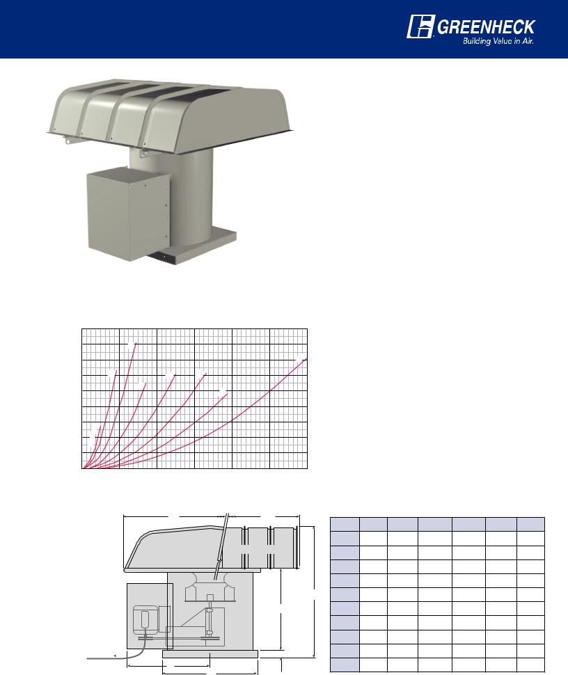
TCBRS Roof Supply Fan
The TCBRS roof mounted supply fan is designed for intake air systems with pressures up to 4 inches of wg and where low sound is required. The TCBRS hood intake is located at a sufficient height above the roof to limit entry of roof debris and snow. In addition, the hood has sufficient intake area to keep velocities low. Filters are available to collect dust and moisture before entering the building. Motor and drive protection is provided with a weatherproof
motor cover. For ease of installation, TCBRS fans are shipped assembled and have curb caps for attaching to roof curbs. TCBRS fans are available in either painted steel or aluminum construction.
Typical applications include:
• Ducted supply systems
• Industrial space supply
• Filtered supply
Pressure Loss (inches)
0.18
0.16
0.14
0.12
0.10
0.08
0.06
0.04
0.02
0.00
System Effect Curves
16
36
|
13 |
|
24 |
|
|
|
|
|
|
|
|
|
|
|
|
18 |
22 |
|
|
|
|
|
|
30 |
|
|
|
|
|
|
|
|
|
|
|
12 |
|
|
|
|
|
|
10, |
|
|
|
|
|
|
09, |
|
|
|
|
|
0 |
4 |
8 |
12 |
16 |
20 |
24 |
|
|
|
CFM x 1000 |
|
|
|
TCBRS fan selections can be made using the TCB inline performance data (pgs. 12 to 31) along with the following system effect curves. The pressure loss determined to the left must be added to the external system static pressure to assure accurate selections. Greenheck’s Computer Aided Product Selection (CAPS) software will add these system effects automatically.
TCBRS fans do not incorporate provisions for internal wiring.
External wiring from the roof to unit must be provided by others 
W |
L |
Dimensional Data |
|
|
|
|
|||
Size |
A |
B |
C |
D |
L |
W |
|||
|
|
||||||||
|
|
09 |
22 |
211/2 |
251/2 |
391/2 |
39 |
46 |
|
Hood End View |
Hood Side View |
10 |
22 |
211/2 |
251/2 |
391/2 |
39 |
46 |
|
|
|
||||||||
|
|
12 |
22 |
211/2 |
251/2 |
391/2 |
39 |
46 |
|
|
|
13 |
24 |
231/2 |
27 |
431/2 |
39 |
54 |
|
|
D |
16 |
28 |
251/2 |
31 |
471/2 |
51 |
55 |
|
|
C |
18 |
34 |
281/2 |
331/2 |
50 |
63 |
64 |
|
|
|
22 |
40 |
34 |
381/2 |
59 |
75 |
73 |
|
|
|
24 |
46 |
361/2 |
45 |
671/2 |
87 |
82 |
|
|
1 |
30 |
52 |
421/4 |
521/2 |
76 |
99 |
88 |
|
|
2 /2 in. |
|
|
|
|
|
|
|
|
B |
A |
36 |
58 |
451/2 |
58 |
851/2 |
111 |
88 |
|
|
|
|
|
|
|
|
|
||
All dimensions shown in inches.
7
Construction Features
Model Number Code
The model number system is designed to completely identify the fan. A detailed explanation of the model number code for TCB fans is shown below.
TCB - 1 - 24 - 30
Tubular Centrifugal |
|
Motor Horsepower |
|
Belt Drive |
|
4 = 1/4 |
30=3 |
TCB - Inline Fan |
|
3 = 1/3 |
50=5 |
TCBRU - Roof Upblast Fan |
Fan Size |
5 = 1/2 |
75=71/2 |
TCBRS - Roof Supply Fan |
09-36 |
7 = 3/4 |
100=10 |
|
|
10=1 |
150=15 |
Level of Construction |
|
15=11/2 |
200=20 |
1 or 2 |
|
20=2 |
|
Standard Construction Features
Inlet & Outlet Flanges Bearings
Flanged inlets and outlets with mounting holes are provided for duct connections (TCB only).
Housing
Housings are continuously welded steel and coated with Permatector™.
Protective Coating
All steel constructed units are coated with Permatector™, a thermosetting polyester urethane. Aluminum units are uncoated.
Type B Spark Resistance
All fans have aluminum wheels and a nonferrous (aluminum) rub ring which surrounds the fan shaft where it passes through the drive cover. This construction meets Type B spark resistant requirements.
Standard bearings are grease lubricated, self-aligning, ball type in pillow block mounts. Bearings are selected for a minimum L(10) life in excess of 80,000 hours {L(50) average life of 400,000 hours} at maximum cataloged operating speeds.
Belt & Bearing Tube
Belts, bearings, and drives are protected from the airstream by heavy gauge belt tubes and bolted bearing covers with shaft seals.
Extended
Lube Lines
Lubrication lines with grease fittings allow bearing lubrication without disassembling the fan.
Optional Construction Features
Aluminum Construction
Aluminum construction is available on the TCB, TCBRU and TCBRS. Aluminum fans are an excellent choice for applications involving moisture or coastal installations.
Easy Access Construction
The Easy Access option is highly recommended to allow for inspection, cleaning and service of internal fan components. By removing one access panel, service to the wheel, shaft, and bearing assembly is possible without removing duct connections. In addition, all internal fan components can be removed from the fan through the easy access panel.
Easy Access construction is available on all levels and sizes of TCB, TCBRU, and TCBRS. Easy Access is also available with aluminum fan construction.
Note: The Easy Access panel is located 180° from the motor position.
8

Optional Construction for
UL 762 Restaurant Exhaust
Inline grease exhaust fans are excellent alternative for kitchen applications when roof or wall mounted ventilators are not practical. The TCB with UL 762 grease option is designed to withstand the demands of high temperature kitchen grease exhaust and high-pressure duct washes.
Leak Resistant Construction Features
1 |
Continuously welded housing and integral duct flanges |
|
|
|
provide air and water tight design. |
|
|
2 |
Bearing cover gasketed and includes a labyrinth shaft seal |
|
|
|
to prevent moisture leakage during normal operation and |
|
|
|
while cleaning with high pressure solvents. |
7 |
|
3 |
Continuously welded belt tube keeps the belts and |
||
|
bearings clean.
4Two threaded drain connections are located 90° from the motor location to allow for removal of grease and moisture.
Mounting and Serviceability Features
5Universal mounting brackets allow for rotation of the motor to the 3 or 9 o’clock position at the jobsite.
6 Duct flanges and access door bolt locations are no more |
5 |
than 4 inches (100 mm) on center per NFPA 96. |
|
4 |
6 |
3 |
|||
|
|
|
|
|
|
|
|
|
|
|
|
|
|
|
|
|
|
4 |
1 |
2 |
7“Easy Access Door” provides access for duct cleaning and allows removal of the wheel, shaft and bearings for maintenance. Gasket is rated for 400°F (200°C) and prevents leakage during operation [Fan is rated for 300°F (149°C) continous operation].
System Design Guidelines
•Inline grease exhaust fans should be installed near the end of the duct run to reduce sound at the hood.
•Inline fan must be securely bolted to the exhaust duct per NFPA-96 guidelines. Greenheck’s companion flanges are recommended for ease of installation.
•Grease exhaust fans and ductwork must maintain 18 inches (46 cm) minimum clearance to combustible material. If the ductwork and fan are insulated, the inspection door must be accessible for maintenance.
•A minimum of 10 ft. (3.0 m) of clearance must be kept from the fan outlet to adjacent buildings, property lines, or the closest point of any air intake or operable window at or below the plane of the exhaust termination.
•Greenheck recommends that all inline grease applications be reviewed by your local code official to ensure compliance with NFPA, IMC, and other local codes.
|
|
|
|
|
|
|
|
UL 762 is concerned with fans |
|
|
|
|
|
designed for removal of smoke and |
|
|
|
|
|
|
|||
|
|
grease laden vapors with airstream |
|
|
|
|
Listed Power |
temperatures up to 300°F. |
|
|
|
|
• |
Meets all UL 705 Requirements |
|
|
|
|
Ventilation for |
|
|
||
|
Restaurant |
• |
Bolted Access Door |
|
|
|
Exhaust |
• |
Drain Connection |
|
|
|
Appliances |
• |
Meets requirements of NFPA 96 |
|
|
|
13G3 |
|
|
||
|
|
Ventilation Control and Fire |
|
|
|
|
Maximum |
|
|
|
|
|
Operating |
|
Protection of Commercial |
|
|
|
Temperature |
|
Cooking Operations |
|
|
|
300°F. |
|
|
|
|
|
|
|
|
|
|
|
|
|
|
|
|
A Tough Package to Beat
|
Roof |
|
|
|
Ambient temperature |
|
|
|
not to exceed 120ºF |
|
|
Duct to heat source |
|
|
|
Air ow |
Minimum duct |
To building |
|
at discharge |
exterior |
||
|
|||
|
Cooling air for |
|
|
|
drives and |
|
|
|
bearings |
|
The TCB inline grease fan is tough to beat when packaged with our full line of kitchen hoods and grease extraction options. Take advantage of Greenheck’s expertise in providing a total solution in kitchen ventilation equipment.
Wall and/or ceiling should enclose fan when used for emergency heat and smoke exhaust. Enclosure shall
be per NFPA 96 or local building codes.
9
Accessories
Belt Guard (TCB only)
Belt guards are totally enclosed to provide protection from rotating pulleys and belts. Belt guards meet OSHA guidelines.
Motor Cover (Weatherhood)
Weatherproof motor covers shield the motor and drive components from dust, dirt and moisture when used in outdoor applications. Motor covers also provide protection from rotating pulleys and belts and meet OSHA guidelines. Motor covers are standard on TCBRU and TCBRS models.
Inlet and Outlet Companion Flanges (TCB only)
Companion inlet flanges and outlet flanges with prepunched holes are available for all fan sizes in painted steel construction.
Inlet and Outlet Guards (TCB, TCBRU)
Removable inlet and outlet guards provide protection for personnel and equipment in non-ducted installations. These guards meet OSHA guidelines. TCBRU fans are available with outlet screens to shield the fan discharge and damper from debris.
Inspection Door
Bolted or hinged doors provide access for cleaning or inspection.
Inspection Section (TCB only)
Inspection sections serve as a length of duct that can be easily removed to provide for complete access to the fan for servicing. Each section includes a bolted inspection door.
Mounting Rails (TCB only)
Mounting rails are required for horizontal mounting of TCB fans when the motor is to be located in the 3 or 9 o’clock position. Mounting rails are also recommended for all vertically mounted inline fans. See page 5 for additional details.
Protective Coatings
Greenheck has a wide offering of protective coatings. Consult Greenheck’s Product Application Guide FA/110-04R, Performance Coatings for Ventilation Products for a complete listing of coatings and a relative resistance chart.
Inlet Vane Dampers (TCB only)
Nested inlet vane dampers for controlling air volume are available on model TCB inline fans with Level 2 steel construction in fan sizes 12 through 36.
Birdscreen / Insect Screen (TCBRS only)
TCBRS fans are available with either aluminum insect screen or birdscreen at the hood intake (Birdscreen is standard).
Roof Curbs (TCBRU, TCBRS)
Prefabricated roof curbs are available to reduce installation time and costs by ensuring compatibility between the fan, the curb and the roof opening.
All curbs are lined with fiberglass insulation to prevent condensation and reduce sound levels. See Greenheck’s roof curb catalog for complete details.
Washable Aluminum Filters (TCBRS only)
Helps trap dust and dirt before it enters the fan. Filters can be removed for cleaning.
Isolators (TCB only)
Both base mount or hanging isolators are available in either neoprene or spring mounts. The isolators are furnished in sets of four and are sized to match the weight of each fan.
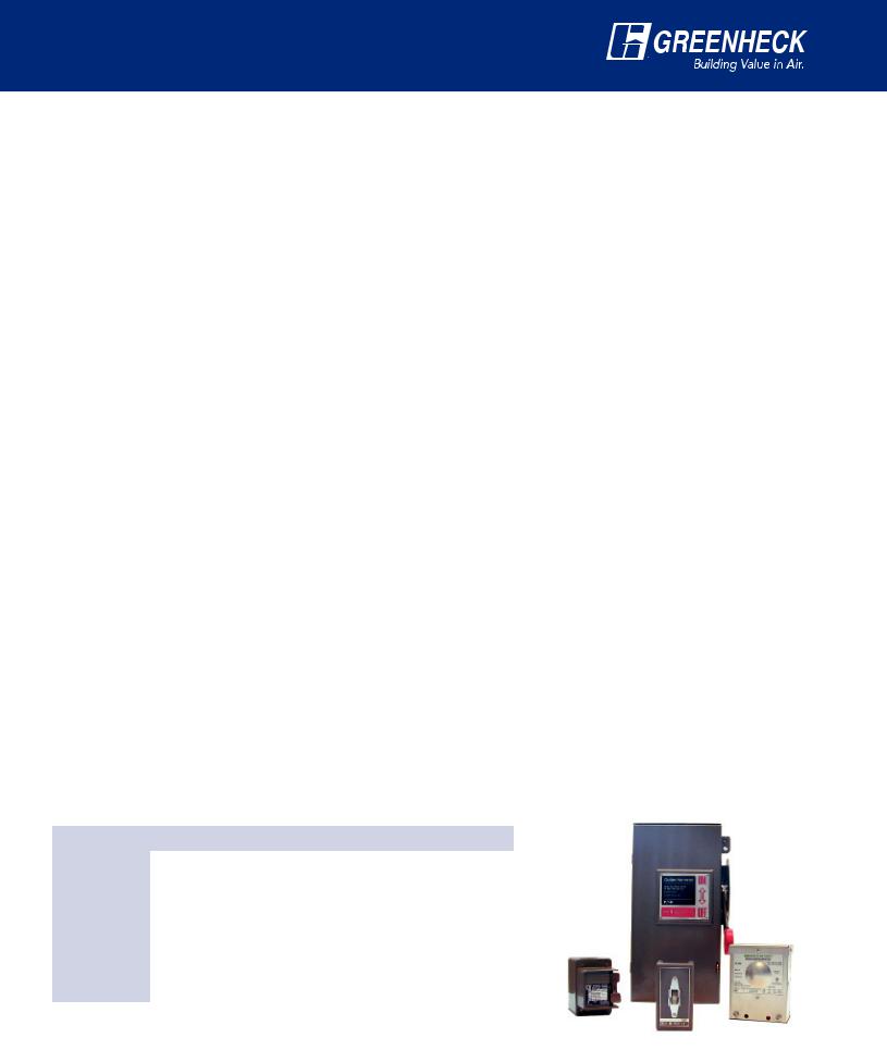
Electrical Accessories
Enclosure |
Application |
Toggle |
Heavy Duty |
|
|
|
|
|
|
NEMA-1 |
Indoor, General Purpose |
Yes |
Yes |
|
|
|
|
|
|
NEMA-12 |
Indoor, Dust/Drip Tight |
Yes |
Yes |
|
|
|
|
|
|
NEMA-3R |
Indoor/Outdoor, Rainproof |
Yes |
Yes |
|
|
|
|
|
|
NEMA-4 |
Indoor/Outdoor, Watertight |
Yes |
Yes |
|
|
|
|
|
|
NEMA-4X |
Indoor/Outdoor, Watertight |
Yes |
Yes |
|
(Corrosion Resistant) |
||||
|
|
|
||
|
|
|
|
|
NEMA-7 & 9 |
Indoor, Hazardous Locations |
Yes |
No |
Toggle type and heavy duty disconnect switches are available for positive electrical shut-off and safety in servicing fans. The following switches are available to meet individual electrical requirements.
10
 Loading...