


|
Document 477179 |
|
Model SP |
® |
Model CSP |
|
Ceiling Exhaust and Inline Fans |
Installation, Operation and Maintenance Manual
Please read and save these instructions for future reference. Read carefully before attempting to assemble, install, operate or maintain the product described. Protect yourself and others by observing all safety information. Failure to comply with instructions could result in personal injury and/or property damage!
WARNING!
To reduce the risk of fire, electric shock, or injury, observe the following:
•Suitable for use with solid state speed controls.
•When cutting or drilling into wall or ceiling, do not damage electrical wiring or other hidden utilities.
•Acceptable for use over a bathtub or shower when installed in a GFCI protected branch circuit. (up through size SP-A390)
•Never place a switch where it can be reached from a tub or shower.
•Ducted fans must always be vented to the outdoors.
•These fans are not recommended for cooking exhaust applications. They are designed primarily for low temperature, clean air applications only. The diagram shows the minimum distances these fans should be placed in relation to cooking equipment.
•Fan/Light combination is not to be installed in a ceiling thermally insulated to a value greater than R40.
CAUTION!
•For general ventilating use only. Do not use to exhaust hazardous or explosive materials and vapors.
127V/60Hz/1-ph |
220V/60Hz/1-ph |
Black wire is “Hot” |
Black wire is “Hot” |
White wire is “Neutral” |
White wire is “Hot” |
Green wire is “Ground” |
Green and Yellow wire |
|
is “Neutral/Ground” |
|
|
Use a device for disconnection from the supply, having a contact separation of at least 3 mm in double poles switch, which must be incorparated in the fixed wiring in accordance with the local electrical wiring rules.
For this fan, precautions must be taken to avoid the back-flow of gases into the room from the open-flue of gas or other fuelburning appliances.
This product must be properly and reliably grounded.
Use this fan at the rated voltage and frequency indicated on the name plate.
Do not allow water to contact electrical parts such as motors or switches.
Do not switch this product on or off in case of gas leakage; otherwise, the electric spark may result in an explosion.
Do not spray or clean this product directly with water or other liquid; otherwise, a short circuit or an electrical shock may occur.
Do not disassemble the unit for reconstruction.
Make sure that its power switch is set to OFF 
 before you touch this product; otherwise, an

 eletrical shock may occur.
This fan must be installed by a qualified technician.
This fan should be installed so that the blades are more than 2.3 m above the floor.
Routine maintenance is required every year. Ensure that the fan is switched off from the main supply power source before removing the guard.
This appliance is not intended for the use by persons (including children) with reduced physical, sensory or mental capabilities,
or lack of experience and knowledge, unless they have been given supervision or instruction concerning use of the appliance by a person responsible for their safety. Children should be supervised to ensure that they do not play with the appliance.
Ceiling Exhaust and Inline Fans 1
®®

Model SP
Model SP is a direct drive ceiling exhaust fan designed for clean air applications where low sound levels are required. Many options and accessories are available such as lights, motion detectors, ceiling radiation dampers and speed controls. Capacities range from 25 to 1,600 cfm (42 to 2,718 m3/hr) and 1 in. wg (248 Pa). AMCA Licensed for Sound and Air Performance.
ENERGY STAR® Certified models include:
SP-A, 50, 70, 90, 200, 250, 290 and 410;
SP-B, 50, 70, 80 and 90.
2Ceiling Exhaust and Inline Fans
Model CSP
Model CSP is a direct drive inline exhaust fan designed for clean air applications where low sound levels are required. Capacities range from 70 to 3,800 cfm (119 to 6,456 m3/hr) and 1 in. wg (248 Pa). AMCA Licensed for Air Performance.
WARNING!
To reduce the risk of fire, electric shock, or injury to persons, observe the following:
•Suitable for use with solid state speed controls.
•Use this unit only in the manner intended by the manufacturer. If you have questions, contact the manufacturer.
•Before servicing or cleaning unit, switch power off at service panel and lock service disconnecting means to prevent power from being switched on accidentally. When the service disconnecting means cannot be locked, securely fasten a prominent warning device, such as a tag, to the service panel.
•Installation work and electrical wiring must be done by qualified person(s) in accordance with all applicable codes and standards, including fire-rated construction.
•Sufficient air is needed for proper combustion and exhausting of gases through the flue (chimney) of fuel burning equipment to prevent back drafting. Follow the heating equipment manufacturer’s guideline and safety standards such as
those published by the National Fire Protection Association (NFPA), and the American Society for Heating, Refrigeration and Air Conditioning Engineers (ASHRAE) and the local code authorities.
•When cutting or drilling into wall or ceiling, do not damage electrical wiring or other hidden utilities.
•Acceptable for use over a bathtub or shower when installed in a GFCI protected branch circuit. (Up through size SP-A390)
•Never place a switch where it can be reached from a tub or shower.
•Ducted fans must always be vented to the outdoors.
•These fans are not recommended for cooking exhaust applications. They are designed primarily for low temperature, clean air applications only. The diagram shows the minimum distance these fans should be placed in relation to cooking equipment.
•Fan/Light combination not to be installed in a ceiling thermally insulated to a value greater than R40.
CAUTION!
•For general ventilating use only. Do not use to exhaust hazardous or explosive materials and vapors.
®

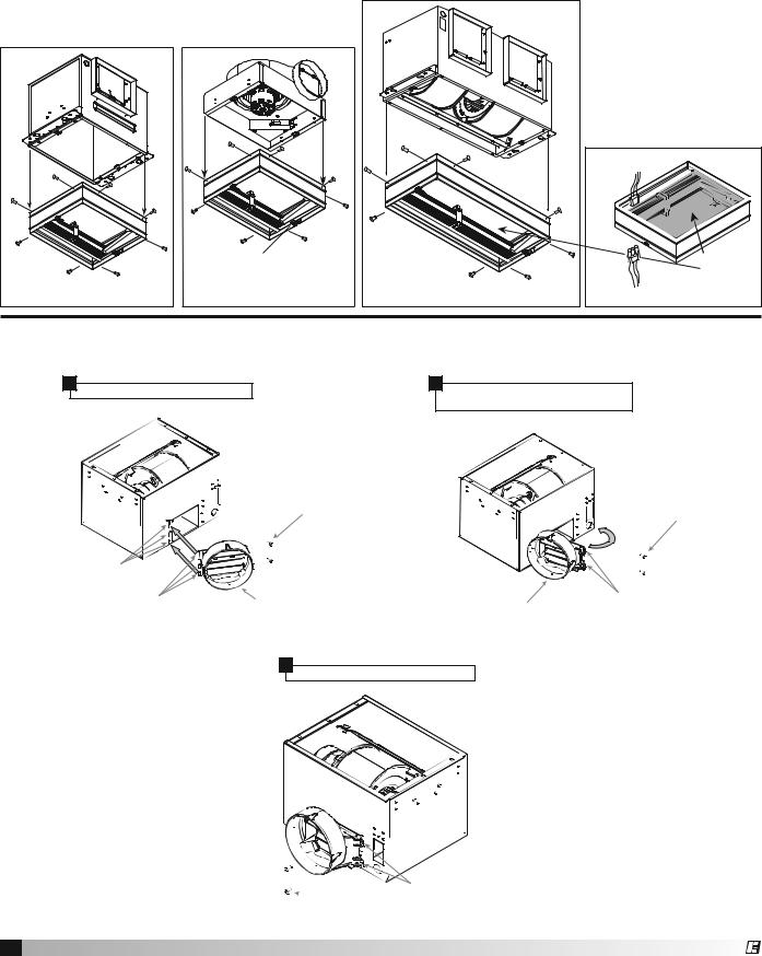
Prepare the fan
Power Assembly
If power assembly (motor, wheel, and scroll) is not installed in housing, insert the electrical plug into fan socket, then slide scroll end of power assembly into fan housing. Attach by using two sheet metal screws provided.
B Model |
A Model |
Remove Wiring Knockout
Remove either top or side wiring knockout, depending on wiring  direction, by
bending it back |
Electrical |
Access |
|
and forth to |
Panel |
|
|
break tabs. |
|
 Knockouts
Ductwork
Check ductwork to see if the fan’s discharge requires rotation from horizontal to vertical discharge.
Airflow |
Airflow |
Fan Rotation
To rotate from horizontal to vertical discharge A-Models Only
A-50-500, 710, 780 Models
Remove the two screws holding the power assembly in and pull power assembly out. Rotate power assembly 180 degrees and put back into fan. Use the same screws to reattach power assembly to fan housing. Flip fan over and remove the four screws holding the discharge duct and damper assembly. Exchange the assembly with plate mounted on top of fan, as shown in these illustrations.
A-700, 900-1500 Models
Remove the eight screws holding the access panel or collar as shown in picture. Rotate the fan housing so the discharge is facing up. Replace access panel or collar and screws.
Access |
Access |
|
Panel |
||
Panel |
||
|
Ceiling Exhaust and Inline Fans 3
®
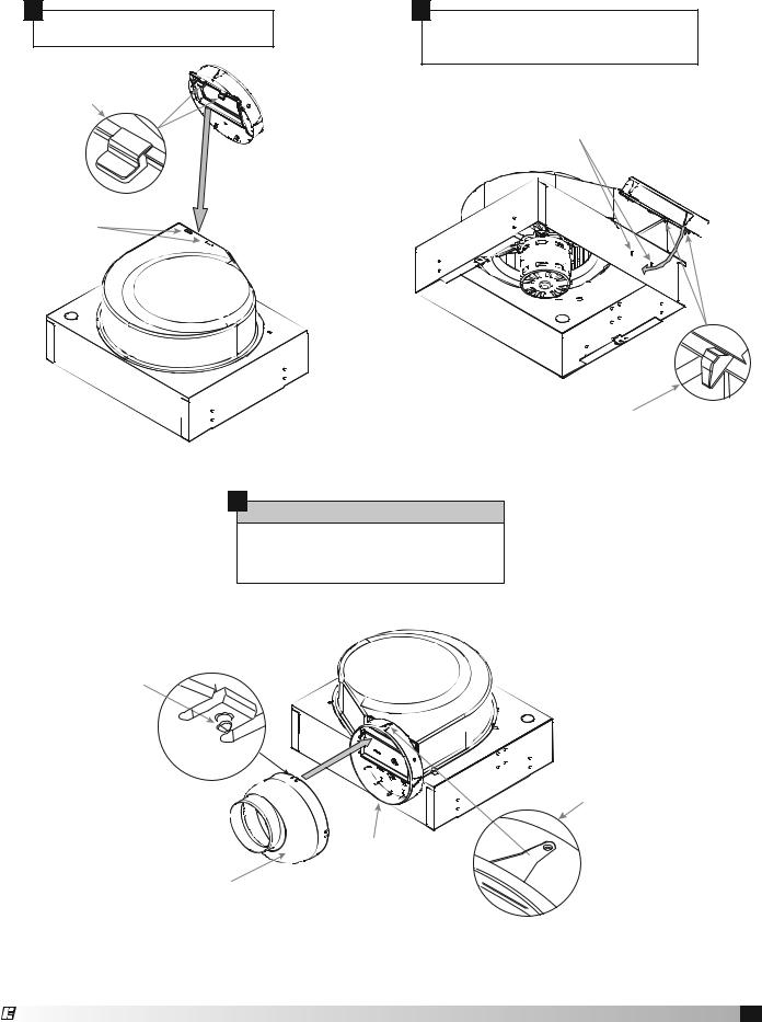
Ceiling Radiation Damper (CRD)
If fan is to be used in a fire resistive membrane ceiling, a ceiling radiation damper must be used.
If the ceiling radiation damper is already mounted to the fan from the factory, proceed to Install the Fan.
|
Attachment Tabs |
A-50-510, 710, 780 Models |
B-Models |
To mount the ceiling radiation damper to fan, make sure grille attachment tabs are facing down. Then place the inlet part of the fan into the ceiling radiation damper collar, and use self-tapping sheet metal screws (by others) to screw through the damper collar and into the fan housing. If the fan/light combination is being used, make sure ceiling
radiation damper has an electrical plug in it.
The electrical plug must
be inserted into the fan.
Make sure the electrical
wire will not interfere with
damper operation as shown in figure below.
|
Wires to ceiling fan |
|
Do not allow |
|
interference |
|
in this area |
A-700, 900-1550 Models |
Wires from lighted grille |
Discharge Installation SP-A 50-90 Models
1
Insert plastic duct tab into SP-A box slots.
Sheet Metal Screw #10x3/8
Phillips Head (PN 415838)
SP-A Box
SP-A Box Slot
Plastic SP-A |
Plastic SP-A |
Duct Adapter Tabs |
Duct Adapter (PN 473388) |
2
Rotate plastic SP-A duct adapter (PN 473388) until the screw tabs meets SP-A box.
Sheet Metal Screw #10x3/8
Phillips Head (PN 415838)
SP-A Box
Screw Tabs
Plastic SP-A
Duct Adapter (PN 473388)
3
Install screws provided to secure discharge.
Screw holes
 Sheet Metal Screw #10x3/8
Phillips Head (PN 415838)
4 Ceiling Exhaust and Inline Fans
®
Discharge Installation SP/CSP-B 50-200 Models
1
Insert SP-B box scroll tab into SP-B box scroll slots.
SP-B
Box Scroll Tabs
2
Rotate plastic SP-B duct adapter (PN 474433) until the two SP-B mounting tabs fully engage into the two SP-B box mounting slots.
SP-B
Box Mounting Slots
SP-B
Box Scroll Slots
SP-B
Box Mounting Tabs
3
OPTIONAL
Align the pins on the TR 6x4 adaptor to the duct pin hole on the SP-B 6-inch duct. Push until the adaptor snaps into place.
TR 6x4 Pin
SP-B
Plastic Duct Pin Hole
|
SP-B |
TR 6x4 |
6-inch |
Plastic Duct |
|
(PN 473324) |
(PN 474433) |
Ceiling Exhaust and Inline Fans 5
®

Install the Fan
1.For best performance, choose a location with the shortest possible duct run and minimum number of elbows. Do not mount near
cooking equipment, as shown in Fig. 1.
2.Attach adjustable mounting brackets to fan, but leave the screws loose until proper height is determined, shown in Fig. 2. Cut hole to dimensions shown in table below:
Do not install fan in this area
45° |
45° |
Fig. 1
Brackets can be used in either position to adapt to most mounting
situations
Bottom Mount
Bottom Mount
Top Mount
Fig. 2
Ceiling Openings
Sizes |
Fan or Fan/Light |
Fan/CRD |
||
|
|
|
|
|
SP-A50, A70, A90 |
107⁄8 x 133⁄8 |
111⁄8 x 137⁄16 |
||
SP-A110, A125, A190 |
||||
|
|
|
||
SP-A200, A250, A290, A390 |
121⁄8 |
x 141⁄4 |
121⁄4 x 143⁄8 |
|
SP-A700 |
233⁄4 |
x 113⁄4 |
241⁄8 x 121⁄4 |
|
SP-A410, A510, A710, A780 |
143⁄4 |
x 183⁄8 |
147⁄8 x 187⁄16 |
|
SP-A900, A1050, A1410, |
143⁄4 x 24 |
147⁄8 x 241⁄8 |
||
A1550 |
||||
|
|
|
||
SP-B 50 - 200 |
141⁄8 |
x 113⁄4 |
143⁄8 x 121⁄4 |
|
NOTE
Model SP-A 50-90 are standard with a round duct. Should Model SP-A 110-190 require a round duct, Model RDC (Round Duct Connector) may be ordered from Greenheck for field installation.
For Frame Construction:
Position unit between
joists. Position brackets |
Slots in the |
|
brackets |
||
such that bottom |
allow fine |
|
adjustment |
||
edge of housing will |
for flush |
|
fit with |
||
be flush with finished |
wall/ceiling |
|
opening |
||
|
||
ceiling, and tighten the |
|
|
adjustable mounting |
Fig. 3 |
|
brackets, shown in |
||
|
||
Fig. 3. |
|
|
For Hanging |
|
|
Installations: |
|
|
Use Greenheck’s |
|
|
optional vibration |
|
|
isolator kit Part Number |
|
|
VI Kit. Using the fan’s |
|
|
standard adjustable |
Fig. 4 |
|
mounting brackets and |
||
|
||
10 by 32 threaded rod |
|
|
(by others), hang unit as |
|
|
shown in Fig. 4. |
|
3.Installation of ductwork
is critical to the performance of the fan, shown in Fig. 5. Straight ductwork (1) or ductwork that turns in
the same direction as the wheel (2) is recommended. Ductwork turning opposite the wheel direction (3) will cause turbulence and back pressure resulting in poor performance.
Fig. 5
1 (GOOD)
2 (GOOD)
AIRFLOW
3
(POOR)
4.Slide ductwork over the fan’s discharge collar and securely attach it with sheet metal screws.
Make sure the screws do not interfere with damper operation. Check damper to make sure it opens freely.
Wire the Fan |
|
|
|
1. Remove wiring cover. |
|
|
|
If fan/light combination |
|
|
|
is being used, make |
|
|
|
sure the fan plug is |
|
|
|
connected to the fan |
|
Fan |
|
receptacle and the light |
|
||
|
Light |
||
|
|
||
plug is connected to |
|
Fan Outlet (top) |
|
the light receptacle, |
Fig. 6 |
Light Outlet (bottom) |
|
shown in Fig. 6. |
|||
|
|||
|
|
Using proper wire
connectors, wire the fan as shown in Fig. 7a. For wiring of light proceed to Fig. 7b.
2.Push all wiring into the unit’s cover and replace wiring cover.
Fig. 7a
115 & 277 Volt
Black wire is “Hot” White wire is “Neutral” Green wire is “Ground”
Fig. 7b
220 - 240 Volt
Black wire is “Hot” White wire is “Hot” Green and Yellow wire is “Neutral/Ground”
6 Ceiling Exhaust and Inline Fans
®
 Loading...