


Part #474612
RV/RVE
Packaged Rooftop Ventilator
Installation, Operation and Maintenance Manual
Please read and save these instructions for future reference. Read carefully before attempting to assemble, install, operate or maintain the product described. Protect yourself and others by observing all safety information. Failure to comply with instructions could result in personal injury and/or property damage!
Model RV/RVE
General Safety Information
Only qualified personnel should install and maintain this system. Personnel should have a clear understanding of these instructions and should be aware of general safety precautions. Improper installation can result in electric shock, possible injury due to coming in contact with moving parts, as well as other potential hazards. Other considerations may be required if high winds or seismic activity are present. If more information is needed, contact a licensed professional engineer before moving forward.
1.Follow all local electrical and safety codes, as well as the National Electrical Code (NEC), the National Fire Protection Agency (NFPA), where applicable.
Follow the Canadian Electric Code (CEC) in Canada.
2.All moving parts must be free to rotate without striking or rubbing any stationary objects.
3.Unit must be securely and adequately grounded.
4.Do not spin wheel faster than maximum cataloged fan RPM. Adjustments to fan speed significantly affect motor load. If the fan RPM is changed, the motor current should be checked to make sure it is not exceeding the motor nameplate amps.
5.Verify that the power source is compatible with the equipment.
6.Never open access doors to the unit while it is running.
WARNING
The roof lining contains high voltage wiring. To prevent electrocution, do not puncture the interior or exterior panels of the roof.
DANGER
•Always disconnect power before working on or near this equipment. Lock and tag the disconnect switch or breaker to prevent accidental power up.
•If this unit is equipped with optional gas accessories, turn off gas supply whenever power is disconnected.
CAUTION
This unit is equipped with a compressed refrigerant system. If a leak in the system should occur, immediately evacuate the area. An EPA Certified Technician must be engaged to make repairs or corrections. Refrigerant leaks may also cause bodily harm.
CAUTION
When servicing the unit, the internal components may be hot enough to cause pain or injury. Allow time for cooling before servicing.
Packaged Rooftop Ventilator 1

Receiving
Upon receiving the product, check to make sure all items are accounted for by referencing the Bill of Lading to ensure all items were received. Inspect each crate for shipping damage before accepting delivery. Notify the carrier if any damage is noticed. The carrier will make notification on the delivery receipt acknowledging any damage to the product. All damage should be noted on all copies of the Bill of Lading which is countersigned by the delivering carrier. A Carrier Inspection Report should be filled out by the carrier upon arrival and filed with the Traffic Department. If damaged upon arrival, file claim with the carrier. Any physical damage to the unit after acceptance is not the responsibility of the manufacturer.
Unpacking
Verify that all required parts and the correct quantity of each item have been received. If any items are
missing, report shortages to your local representative to arrange for obtaining missing parts. Sometimes it is not possible that all items for the unit be shipped together due to availability of transportation and truck space.
Confirmation of shipment(s) must be limited to only items on the Bill of Lading.
Handling
Units are to be rigged and moved by the lifting brackets provided. This model is not designed for forklifting. Location and number of lifting points varies by model and size and all provided lifting brackets must be used to properly support the unit during handling. Handle each unit in such a way as to keep from scratching or chipping the coating. Damaged finish may reduce the ability of the unit to resist corrosion.
Storage
Units are protected against damage during shipment. If the unit cannot be installed and operated immediately, precautions need to be taken to prevent deterioration of the unit during storage. The user assumes responsibility of the unit and accessories during storage. The manufacturer will not be responsible for damage during storage. These suggestions are provided solely as a convenience to the user.
Inspection and Maintenance During Storage
While in storage, inspect units once per month. Keep a record of inspection and maintenance performed. If moisture or dirt accumulations are found on the parts, the source should be located and eliminated. At each inspection, rotate all moving parts by hand ten to fifteen revolutions to distribute lubricant on motor and bearings. If paint deterioration begins, consideration should be given to touch-up or repainting. Units with special coatings may require special techniques for touch-up or repair.
Machined parts coated with rust preventative should be restored to good condition promptly if signs of rust occur. Immediately remove the original rust preventative coating with petroleum solvent and clean with lint-free
2 Packaged Rooftop Ventilator
cloths. Polish any remaining rust from the surface with crocus cloth or fine emery paper and oil. Do not destroy the continuity of the surfaces. Wipe clean thoroughly with Tectyl® 506 (Ashland, Inc.) or the equivalent. For hard to reach internal surfaces or for occasional use, consider using Tectyl® 511M Rust Preventative or WD 40® or the equivalent.
Product Overview
A horizontally configured High Percentage Outdoor Air unit designed for installation either indoors or outdoors. Each unit has multiple options for cooling and/or heating. The unit is designed to replace air that is exhausted from the building and also heat and cool, as needed. The air volume produced by the unit is constant, but can be optionally modulated to provide a
variable air volume (VAV) and recirculation is also offered as an option.
Cooling
Units have the following cooling options available:
•Packaged DX
•Split DX
•Chilled water coil
Units with packaged DX are shipped fully charged with refrigerant and are ready for operation upon arrival.
Heating
There are three different optional heat sources that can be ordered for this unit:
•Indirect gas-fired furnace with one or two sets of heat exchangers
•Electric heat with infinitely variable SCR control
•Hot water coil
Airflow Arrangement
The unit is capable of Constant Air Volume (CAV), Variable Air Volume (VAV), 100% Outdoor Air and have recirculating air options.
Safety Listing
Models are listed per ANSI/UL 1995, Heating and Cooling Equipment and are ETL Certified.
Supplemental Installation, Operation and Maintenance Manuals
Refer to the following Greenheck Installation, Operation and Maintenance Manuals for additional information:
•Indirect Gas-Fired Heat Modules
•PCO3 DDC Controller Operating Manual
•Housed Plenum Array, Plug and Plenum
Models and Capacities
The packaged rooftop ventilator is built on three different platform sizes.
Model |
Cooling Capacity |
|
|
RV-35/RVE-35 |
5 to 15 tons |
|
|
RV-50/RVE-50 |
10 to 25 tons |
|
|
RV-80/RVE-80 |
15 to 29 tons |
|
|

Table of Contents
General Safety Information. . . . . . |
. . . . 1 |
Receiving, Handling, Storage . . . . . |
. . . . 2 |
Product Overview |
|
Cooling.. . . . . . . . . . . . . . . . . . 2 |
|
Heating. . . . . . . . . . . . . . . . . . |
2 |
Airflow Arrangement . . . . . . . . . . . . . 2 |
|
Safety Listing. . . . . . . . . . . . . . . . 2 |
|
Supplemental Installation, Operation and |
|
Maintenance Manuals. . . . . . . . . . . |
2 |
Models and Capacities. . . . . . . . |
. . . . 2 |
Subassemblies |
|
Blower. . . . . . . . . . . . . . . . . . .4 |
|
Coils. . . . . . . . . . . . . . . . . . . .4 |
|
Compressors. . . . . . . . . . . . . . . . 4 |
|
Dampers. . . . . . . . . . . . . . . . . |
4 |
Optional Barometric Relief Damper.. . . |
. . . . 4 |
Electric Heater. . . . . . . . . . . . . . . .4 |
|
Filters. . . . . . . . . . . . . . . . . . . 4 |
|
Indirect Gas-Fired Furnace. . . . . . . |
. . . .4 |
Packaged DX System. . . . . . . . . |
. . . .4 |
Split DX . . . . . . . . . . . . . . . . . . 4 |
|
Vestibule. . . . . . . . . . . . . . . . . |
4 |
Installation |
|
Typical Unit Weights and Dimensions. . . |
. . . .5 |
Service Clearances. . . . . . . . . . . . . |
5 |
Additional Clearances for Packaged DX. . |
. . . .6 |
Handling Concerns for Units with Package DX. . . 6 Lifting. . . . . . . . . . . . . . . . . . . 6
Roof Curb Mounting . . . . . . . . . . |
. |
. |
. |
7 |
Optional Piping Vestibule. . . . . . . . . . . |
|
|
|
7 |
Ductwork Configurations. . . . . . . . . . . .7 |
||||
Rail Mounting and Layout. . . . . . . . |
. |
. |
. |
8 |
Recommended Electrical and |
|
|
|
|
Gas Supply Entry Locations . . . . . . |
. . . .8 |
|||
Gas Supply Piping. . . . . . . . . . . |
. |
. |
. |
8 |
Gas Connections. . . . . . . . . . . . . . .8 |
||||
Electrical Information. . . . . . . . . . . . .9 |
||||
Determine the Size of Main Power Lines . . . . .9 |
||||
Determine the Size of Electric Heater Wiring. . . 9 |
||||
Provide the Opening(s) for the Electrical |
|
|
|
|
Connections.. . . . . . . . . . . . . . . 9 |
||||
Connect the Power Supplies. . . . . . |
. . . .9 |
|||
Wire the Optional Convenience Outlet . . |
. . . .9 |
|||
Connect Field-Wired Low Voltage Components.. 9 |
||||
Field-Provided Disconnect. . . . . . . . . . .9 |
||||
Plumbing / Piping Overview |
|
|
|
|
Split DX / Water Coil Connections. . . . . . . |
|
|
|
10 |
Condensate Drain Trap. . . . . . . . . |
. |
. |
.10 |
|
Control Center Components |
|
|
|
|
Main Control Center. . . . . . . . . . . . |
|
|
|
11 |
Optional Indirect Gas-Fired Furnace. . . . |
. |
. |
.11 |
|
Component Operation |
|
|
|
|
Phase Monitor. . . . . . . . . . . . . . . 12 |
||||
Variable Frequency Drive. . . . . . . . |
. |
. |
. |
12 |
Supply Fan VFD Sequence. . . . . . . |
. |
. |
. |
12 |
Optional Exhaust Fan VFD Sequence. . . |
. |
. |
. |
12 |
Factory-Installed Refrigeration System |
|
|
|
|
||||
Components. . . . . . |
. . . . . . . |
. . |
|
|
|
13 |
||
Start-Up – Unit |
|
|
|
|
|
|
||
Model and Serial Number. . . . . . . |
. . |
. |
.14 |
|||||
Pre-Start-Up Checklist. . . . . . |
. . . . . |
|
|
|
15 |
|||
Special Tools Required . . . . . . . . |
. . . .15 |
|||||||
Start-Up Procedure. . . . . . . . . . . . . 15 |
||||||||
Voltage Imbalance. . . . . . . . . . . . . .15 |
||||||||
Start-Up Checklist. . . . . . . . . . . . . .16 |
||||||||
Start-Up – Components |
|
|
|
|
|
|||
Fan. . |
. . . . . . . . . . . . . . |
. . . .17 |
||||||
Supply Fan (Plenum Type). . |
. . . . . |
. . . .17 |
||||||
Fan Wheel Rotation Direction . . . . . . |
. |
. |
. |
17 |
||||
Supply/Exhaust Fan . |
. . . . . . |
. . . . . |
|
|
|
17 |
||
Vibration. . |
. . . . . . . . . . . . . . . .17 |
|||||||
Discharge Air Temperature Sensor . . . . |
. |
. |
. |
17 |
||||
Optional Energy Wheel |
|
|
|
|
|
|||
Start-Up. . . . . . . . . . . . . . . . . .18 |
||||||||
Drive Belt. . . . . . . . . . . . . . . . . 18 |
||||||||
Adjust the Air Seals. . . . . . . . . . |
. |
. |
. |
18 |
||||
Sequence of Operation. . . . . . . . |
. . |
. |
.18 |
|||||
Maintenance |
. . . . . . . |
. . . . . . . |
. |
|
|
|
19 |
|
Inspection. . |
. . . . . . . |
. . . . . . . |
|
|
|
|
19 |
|
Wheel Disassembly. . . . . . . . . . . . . 19 |
||||||||
Cleaning. . |
. . . . . . . . . . . . . . . .19 |
|||||||
Reassembly. . . . . . . . . . . . . . . . 19 |
||||||||
Energy Recovery Wheel Belt. . . . . . |
. . . .19 |
|||||||
Energy Recovery Wheel Bearings. . . . |
. . . .19 |
|||||||
Energy Recovery Wheel - Troubleshooting. |
. |
. |
. |
20 |
||||
Troubleshooting |
|
|
|
|
|
|
||
Alarms |
|
|
|
|
|
|
|
|
DDC Controller . . . . . . . . . . . . . .20 |
||||||||
Phase Monitor. . . . |
. . . . . . . |
. . . |
|
|
|
20 |
||
Variable Frequency Drive. . . . . . . |
. |
. |
. |
20 |
||||
Optional FX05 Furnace Controller. . . |
. . . .20 |
|||||||
Optional Digital Scroll Compressor Controller. . 20 |
||||||||
Unit . . . |
. . . . |
. . . . . . |
. . . . . . |
|
|
|
|
21 |
Refrigeration Circuit. |
. . . . . . . . . |
. . 22-25 |
||||||
Routine Maintenance |
|
|
|
|
|
|||
Monthly . . . . . . . . . . . . . . . . . .26 |
||||||||
Semiannually. . . . . . . . . . . . . . . .26 |
||||||||
Annually. . . . . . . . . . . . . . . . . .26 |
||||||||
Units with Packaged DX, Semiannually. . . |
. . |
|
|
26 |
||||
Maintenance Procedures |
|
|
|
|
|
|||
Lubrication. |
. . . . . . . . . . . . . . . .26 |
|||||||
Dampers. . . |
. . . . . . . |
. . . . . . |
. |
|
|
|
26 |
|
Gas Furnace |
. . . . . . . |
. . . . . . . |
. |
|
|
|
26 |
|
Fan Motors. |
. . . . . . . |
. . . . . . |
. . |
|
|
|
27 |
|
Fan Wheel and Fasteners . . . . . . . |
. . . .27 |
|||||||
Internal Filter Maintenance . . . . . . . |
. |
. |
. |
27 |
||||
Outdoor Air Filters. . . . . . . . . . |
. . . .27 |
|||||||
External Filter Maintenance. . . . . . . |
. |
. |
. |
27 |
||||
Coil Maintenance. . |
. . . . . . . . . |
. |
. |
. |
27 |
|||
Maintenance Log. . |
. . . . . . . . . |
Backcover |
||||||
Warranty . . . . . . . . . . . . . . |
Backcover |
|||||||
Packaged Rooftop Ventilator 3
®
Subassemblies
Blower
Either one or two plenum-type fans. All units are equipped with a plenum fan for Supply Air and a second may be selected for Exhaust (Relief) Air.
Coils
Evaporator coil (optional)
Condenser coil (optional, packaged DX only) Water coil (optional)
Reheat coil (optional)
Compressors
Each unit having packaged DX will have either one or two refrigerant compressors. Optionally, one the compressors may be a digital scroll type compressor.
Dampers
Motorized intake air damper, motorized recirculating damper. Optional return air damper. Optional gravitytype exhaust damper.
Optional Barometric Relief Damper
Used during economizer mode of the unit when building pressure increases, relief damper will open due to over pressurization.
Electric Heater
An SCR controlled electric heater (not shown) is available on the units. It requires a separate power supply and has its own control panel. See unit-specific wiring diagram.
Filters
Two-inch thick metal mesh filters in the optional Outdoor Weatherhood air intake, 2-inch thick pleated paper MERV 8 (standard) or MERV 13 filters in the airstream. Optional 4-inch thick filter bank with 2-inch thick MERV 8 and 2-inch thick MERV 13 pleated paper
Final Filters.
Indirect Gas-Fired Furnace
The optional model PVG furnace is available on housing sizes 35 and 50. Housing size 80 uses the optional model PVF furnace.
Packaged DX System
Any unit may be ordered with a packaged DX system. It will include either one or two compressors, a condenser coil(s) and evaporator coil(s) and all needed components. Units that have packaged DX are charged with R-410A refrigerant. Do not use tools or parts designed for other refrigerants on these units.
Split DX
The unit may be ordered with a split DX system for connection to a building cooling system.
Vestibule
Some units may be ordered with a factory-assembled vestibule that is to be field-attached to the side of the unit. See lifting instructions.
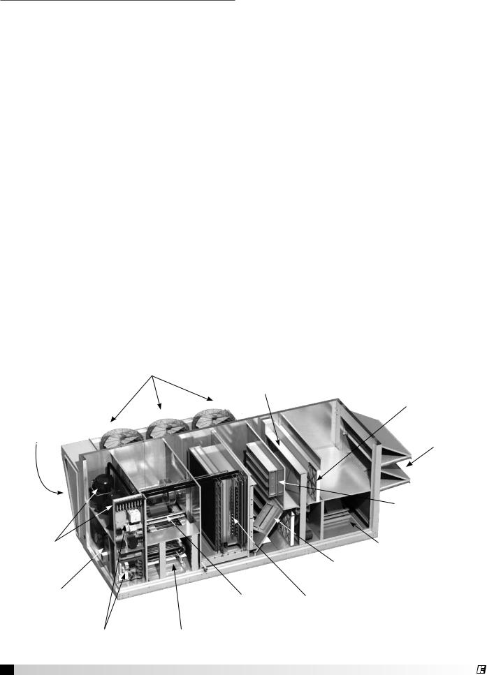
Open view of Model RVE showing optional condenser coil, fans and enthalpy wheel.
Condenser Fans
(optional)
Energy Wheel (RVE)
(optional) Final Filters
(on coil face)
Condenser Coils
(optional) Weatherhood Filters
(metal mesh)
|
|
Intake Air |
|
|
Damper |
Packaged DX |
|
Plenum-Type |
Compressors |
|
Exhaust Air Blower |
(optional) |
|
Recirculating |
|
|
|
|
|
Damper |
Furnace Vest Plate |
Plenum-Type |
Coils |
and |
||
Furnace Control Center |
Supply Air Blower |
(optional) |
(optional) |
|
|
Main Control |
Indirect Gas-Fired Furnace |
|
Center |
(optional) |
|
4 Packaged Rooftop Ventilator |
|
® |

Installation
Typical Unit Weights and Dimensions
PLAN VIEW |
ELEVATION |
|
A |
|
|
L |
|
|
|
|
|
|
|
|
|
|
Return Air Inlet |
|
Control |
|
|
|
|
|
|
||
Outdoor Air |
|
|
Supply Filters |
|
|
Outdoor Air |
|
Supply |
|
|||
Weatherhood |
|
|
|
DX Coil |
|
Center |
|
|
Damper |
|
Blower |
Compressors |
W |
|
|
|
|
|
|
H |
|
|
|
|
|
|
|
|
|
|
|
|
|
|
|
|
|
|
|
|
|
|
|
|
Supply Air |
|
|
|
|
|
|
|
|
|
|
|
|
Discharge |
|
|
|
|
|
|
J |
|
|
|
|
|
|
Recirc |
|
Indirect Gas |
|
|
|
|
|
|
|
|
|
|
Damper |
|
|
Heater |
|
|
Unit |
A |
|
|
L |
W |
J |
J |
|
H |
Unit |
Final Filter |
|
Outdoor Air |
|
|
|
Condensing |
Optional |
|
|
|||||
Size |
|
Length |
Width |
|
Height |
Weight |
Size |
|
||||
Weatherhood |
Section |
Piping Vestibule |
|
|||||||||
|
|
|
|
|
|
|
||||||
RV-35 |
21.5 |
95.6 |
52.5 |
28.8 |
26.0 |
58.2 |
2,600 |
20x20 |
|
|
|
|
|
|
|
|
|
RV-50 |
21.5 |
108.8 |
64.0 |
32.0 |
26.0 |
70.5 |
3,600 |
20x25 |
|
|
|
|
|
|
|
|
|
RV-80 |
26.5 |
117.0 |
68.0 |
30.0 |
26.0 |
82.0 |
4,500 |
20x25 |
|
|
|
|
|
|
|
|
|
RVE-35 |
21.5 |
147.5 |
52.5 |
28.8 |
26.0 |
58.2 |
3,000 |
20x20 |
|
|
|
|
|
|
|
|
|
RVE-50 |
21.5 |
163.1 |
64.0 |
32.0 |
26.0 |
70.5 |
4,100 |
20x25 |
|
|
|
|
|
|
|
|
|
RVE-80 |
26.5 |
178.3 |
68.0 |
30.0 |
26.0 |
82.0 |
5,100 |
20x25 |
All dimensions are shown in inches. Weight is in pounds.
Note: If RV unit is ordered with optional exhaust (relief) fan, corresponding RVE dimensions will apply.
Service Clearances
CC End
ACS
Clearance
Clearance
OA End |
NA |
ACS = Access
CC = Control Center
NA = Non-Access
OA = Outdoor Air Weatherhood
Unit Size |
ACS |
CC End |
OA End |
*NA from Unit |
*NA from CS |
*NA from Vest |
RV-35/RVE-35 |
36 |
36 |
42 |
24 |
42 |
30 |
|
|
|
|
|
|
|
RV-50/RVE-50 |
36 |
36 |
42 |
24 |
42 |
30 |
|
|
|
|
|
|
|
RV-80/RVE-80 |
36 |
36 |
52 |
24 |
42 |
30 |
|
|
|
|
|
|
|
All dimensions are shown in inches.
*NA from Unit = no condensing section or piping vestibule *NA from CS = condensing section
*NA from Vest = piping vestibule
Packaged Rooftop Ventilator 5
Additional Clearances for Packaged DX Units
Packaged DX units require additional clearance because they must have unrestricted air movement around the condenser coil and condenser fans. Hot air is being discharged from the condenser fans during operation. Enough clearance must be provided to avoid recirculation or coil starvation. When equipped with condenser coils, the unit should never be placed under an overhang or inside a building. A minimum of 48 inches above the condenser fans is acceptable, but unobstructed is strongly recommended.
Minimum 48 inches clearance
Condenser Fans
Minimum 42 inches clearance
Condenser Coil
End view of roof top unit with Packaged DX
Handling Concerns for Units with Packaged DX
Units having packaged DX have a system that is pressurized with refrigerant and if it is damaged, the refrigerant could leak into the atmosphere or cause bodily harm due to the extreme cold nature of
expanding refrigerant. Use protective equipment such as gloves and safety glasses to minimize or prevent injury in case of a system leak during installation.
Before Lifting - Vestibule
Determine whether or not the unit has a vestibule that must be field-attached to the side of the unit. Vestibules are shipped assembled but detached from the unit. They have lifting lugs on them so they can also be lifted by crane, but the installed location of the unit may make it preferable to install the vestibule on the unit prior to lifting.
Before Lifting - Field Power Access
Determine where high voltage and low voltage wiring is to be brought into the cabinet. If wiring is to be brought into the cabinet through the floor, see Alternate Supply Entry Locations in this manual. If unit is to be installed on a roof, cut access openings in the roof deck as needed.
6 Packaged Rooftop Ventilator
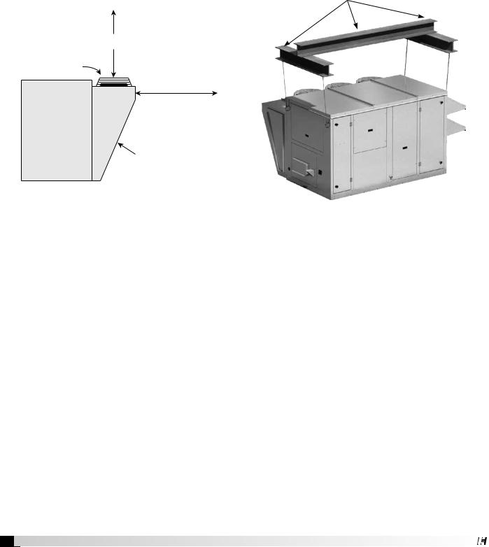
Lifting
1.Before lifting, be sure that all shipping materials have been removed from unit.
2.To assist in determining rigging requirements, weights are provided in the Unit Weights & Dimensions section of this manual.
3.Unit must be lifted by all lifting lugs provided at top of unit.
4.Spreader bars must span the unit to prevent damage to the cabinet by the lift cables.
Use spreader bars to prevent damage to cabinet.
5.Always test-lift the unit to check for proper balance and rigging before hoisting to desired location.
6.Never lift unit by weatherhood.
7.Never lift units in windy conditions.
8.Preparation of curb and roof openings should be completed prior to lifting unit to the roof.
9.Check to be sure that gasketing (supplied by others) has been applied to the top of the curb prior to lifting the unit and setting on the curb.
10. Do not use fork lifts for handling unit.
Roof Curb Mounting
Roof curb details, including duct locations and dimensions, are to be found in the roof curb assembly instructions.
Rooftop units require curbs to be mounted first. The duct connections must be located so they will be clear of structural members of the building.
1. Factory Supplied Roof Curbs
Roof curbs are Model GKD which are shipped in a knockdown kit (includes duct adapters) and require field assembly (by others). Assembly instructions are included with the curb kit.
2. Install Curb
Locate curb over roof opening and fasten in place. Check that the diagonal dimensions are within ± 1/8 inch of each other and adjust as necessary. For proper coil drainage and unit operation, it is important that the installation be level. Shim the curb as required to level. Install gasketing on top surface of curb (provided by others).
3. Install Ductwork
Installation of all ducts should be done in accordance with SMACNA and AMCA guidelines. Duct adapters are provided to support ducts prior to setting the unit.
4. Set the Unit
Lift unit to a point directly above the curb and duct openings. Guide unit while lowering to align with duct openings. Roof curbs fit inside the unit base. Make sure the unit is properly seated on the curb and level.
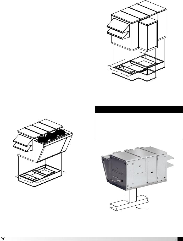
Optional Piping Vestibule
If the unit was ordered with the vestibule, the NA (NonAccess side) clearance dimension must be measured from the vestibule.
L


W
Typical Unit with Piping Vestibule and
Factory-Supplied Curb Kit
Ductwork Configurations
NOTE
Downblast Discharge Ductwork - whenever downblast discharge is used, the ductwork directly beneath the unit must be connected with either a “T” or an “L” configuration and the area directly beneath the heat source must not have any openings such as louvers or grates.
L
W
Typical Unit with Condensing Section and |
|
Factory-Supplied Curb Kit |
|
5. Install Vestibule |
|
If unit was ordered with a vestibule and it has not yet |
|
been attached to the unit, caulk and attach the vestibule |
No louvers or grates |
at this time. |
|
Packaged Rooftop Ventilator 7

Rail Mounting and Layout
•The units may be installed on rails provided and installed by others. Ensure that rails are designed to handle the weight of the unit and provide proper load distribution on building supports.
•Make sure that rail positioning does not interfere with the openings on the unit.
•Rails should run the width of the unit and extend beyond the unit a minimum of 12 inches on each side.
•Set unit on rails.
Typical Unit Installed on Rails Supplied by Others
Recommended Electrical and Gas
Supply Entry Locations
Manufacturer recommends that electrical service and gas supply be brought into the cabinet through the end wall, as shown below. There are three penetrations into the cabinet that are required; one for high voltage
supply wiring, one for low voltage control wiring and one for either gas supply or high voltage supply wiring for an electric heater.
Alternate Supply Entry Locations
Disconnect Switch for electric heater.
Present only if electric heat is selected.
Terminate heater supply wiring here.
 Optional Main Disconnect Switch (Terminate high voltage supply wiring here or at power distribution block).
|
RECOMMENDED LOCATION |
|
|
for low voltage control wiring. |
|
RECOMMENDED LOCATION: |
|
|
Factory-provided opening for gas |
RECOMMENDED LOCATION |
|
supply. If electric heat is ordered, |
||
for field-supplied high voltage |
||
use this location for high voltage |
||
supply wiring. |
||
supply wiring for heater. |
||
|
Recommended Gas and Electric Supply Entry Locations
8 Packaged Rooftop Ventilator
Each installation is unique and as a result, alternate entry locations may be field-located. Before using any alternate entry location, verify the suitability of the location and ensure the use of an alternate location does not interfere with unit wiring, components or functionality.
WARNING
Never drill holes in the roof of the unit! There is high voltage wiring located between the inner and outer roof panels. Damage to the wiring could cause severe bodily harm or death.
Gas Supply Piping
Units with indirect gas-fired furnaces require fieldsupplied and installed gas supply piping.
Ground |
Gas to |
Joint |
Controls |
Union |
|
Gas Cock
From Gas Supply
Bleeder Valve or 1/8 in Plugged Tap
 8 in. Trap
Typical Gas Supply Piping Connection
Gas Connections
If this unit is equipped with an indirect gas-fired furnace, connection to an appropriate gas supply line will be required. For complete information on installation procedures for the optional gas furnace, refer the
Indirect Gas-Fired Heat IOM. See also Recommended Electrical and Gas Locations in this manual.
Electrical Information
WARNING
The roof lining contains high voltage wiring. To prevent electrocution, do not puncture the interior or exterior panels of the roof.
WARNING
To prevent injury or death due to electrocution or contact with moving parts, lock disconnect switch open.
For units with a gas furnace, if you turn off the power supply, turn off the gas.
important
Before connecting power to the unit, read and understand the following instructions and wiring diagrams. Complete wiring diagrams are attached on the inside of the control center door(s).
important
All wiring should be done in accordance with the latest edition of the National Electric Code ANSI/NFPA 70 and any local codes that may apply. In Canada, wiring should be done in accordance with the Canadian Electrical Code.
important
The equipment must be properly grounded and bonded. Any wiring running through the unit in the airstream must be protected by metal conduit, metal clad cable or raceways.
caution
If replacement wire is required, it must have a temperature rating of at least 105ºC, except for an energy cut-off or sensor lead wire which must be rated to 150ºC.
danger
High voltage electrical input is needed for this equipment. This work should be performed by a qualified electrician.
caution
Any wiring deviations may result in personal injury or property damage. Manufacturer is not responsible for any damage to, or failure of the unit caused by incorrect final wiring.
Determine the Size of the Main Power Lines
The unit’s nameplate states the voltage and the unit’s
MCA. The main power lines to the unit should be sized accordingly. The nameplate is located on the outside of the unit on the control panel side.
Determine the Size of Electric Heater Wiring
An optional electric heater may require a separate power supply. The power connection should be made to the factory-provided electric heater disconnect and must be compatible with the ratings on the nameplate, supply power voltage, phase and amperage. Consult ANSI/NFPA 70 and CSA C22.1 for proper conductor sizing.
Provide the Opening(s) for the Electrical Connections
Electrical openings vary by unit size and arrangement and are field-supplied.
Connect the Power Supplies
Connect the main power lines and electric heater power lines to the disconnect switches or terminal blocks and main grounding lug(s). Torque field connections to manufacturer’s recommendations.
Wire the Optional Convenience Outlet
The convenience outlet requires a separate 115V power supply circuit. The circuit must include short circuit protection which may need to be supplied by others.
Connect Field-Wired Low Voltage Components
Most factory-supplied electrical components are prewired. To determine what electrical accessories require additional field-wiring, refer to the unit-specific wiring diagram located on the inside of the control center access door.
The low voltage control circuit is 24 VAC and control wiring should not exceed 0.75 ohms.
Control wires should not be run inside the same conduit as that carrying the supply power. Make sure that field-supplied conduit does not interfere with access panel operation. All low voltage wiring should be run in conduit wherever it may be exposed to the weather.
If wire resistance exceeds 0.75 ohms, an industrialstyle, plug-in relay should be added to the unit control center and wired in place of the remote switch (typically between terminal blocks R and G on the terminal strip. The relay must be rated for at least 5 amps and have a 24 VAC coil. Failure to comply with these guidelines may cause motor starters to “chatter” or not pull in which can cause contactor failures and/or motor failures.
Field-Provided Disconnect
If field-installing an additional disconnect switch, it is recommended that there is at least four feet of service room between the switch and system access panels. When providing or replacing fuses in a fusible
disconnect, use dual element time delay fuses and size according to the rating plate.
Packaged Rooftop Ventilator 9
®
 Loading...