


Part #470656
® |
IG/IGX Make-Up Air Unit |
|
Installation, Operation and Maintenance Manual
Please read and save these instructions. Read carefully before attempting to assemble, install, operate or maintain the product described. Protect yourself and others by observing all safety information. Failure to comply with instructions could result in personal injury and/or property damage! Retain instructions for future reference.
2. The rotation of the wheel is critical. It must be free to rotate without striking or rubbing any stationary objects.
3. Motor must be securely and adequately grounded.
4. Do not spin fan wheel faster than the maximum cataloged fan rpm. Adjustments to fan speed significantly effects motor load. If the fan RPM is changed, the motor current should be checked to make sure it is not exceeding the motor nameplate amps.
5. Do not allow the power cable to kink or come in contact with oil, grease, hot surfaces or
chemicals. Replace cord immediately if damaged.
6. Verify that the power source is compatible with the equipment.
7. Never open blower access doors while the fan is running.
General Safety Information
Only qualified personnel should install this unit. Personnel should have a clear understanding of these instructions and should be aware of general safety precautions. Improper installation can result in electric shock, possible injury due to coming in contact with moving parts, as well as other potential hazards. Other considerations may be required if high winds
or seismic activity are present. If more information is needed, contact a licensed professional engineer before moving forward.
1.Follow all local electrical and safety codes, as well as the National Electrical Code (NEC), the National Fire Protection Agency (NFPA), where applicable.
Follow the Canadian Electric Code (CEC) in Canada.
DANGER
Always disconnect power before working on or near a unit. Lock and tag the disconnect switch or breaker to prevent accidental power up.
CAUTION
When servicing the unit, motor may be hot enough to cause pain or injury. Allow motor to cool before servicing.
FOR YOUR SAFETY
If you smell gas:
1.Open windows.
2.Do not touch electrical switches.
3.Extinguish any open flame.
4.Immediately call your gas supplier.
FOR YOUR SAFETY
The use and storage of gasoline or other flammable vapors and liquids in open containers in the vicinity of this appliance is hazardous.
WARNING
Improper installation, adjustment, alteration, service or maintenance can cause property damage, injury or death. Read the installation, operating and maintenance instructions thoroughly before installing or servicing this equipment.
1 Model IG / IGX Make-Up Air
®
®

Receiving
Upon receiving the product check to make sure all items are accounted for by referencing the bill of lading to ensure all items were received. Inspect each crate for shipping damage before accepting delivery. Notify the carrier if any damage is noticed. The carrier will make notification on the delivery receipt acknowledging any damage to the product. All damage should be noted on all the copies of the bill of lading which is countersigned by the delivering
carrier. A Carrier Inspection Report should be filled out by the carrier upon arrival and the Traffic Department. If damaged upon arrival, file claim with carrier. Any physical damage to the unit after acceptance is not the responsibility of Greenheck Fan Corporation.
Unpacking
Verify that all required parts and the correct quantity of each item have been received. If any items are missing report shortages to your local representative to arrange for obtaining missing parts. Sometimes it is not possible that all items for the unit be shipped together due to availability of transportation and truck space. Confirmation of shipment(s) must be limited to only items on the bill of lading.
Handling
Units are to be rigged and moved by the lifting brackets provided or by the skid when a forklift is used. Location of brackets varies by model and size. Handle in such a manner as to keep from scratching or chipping the coating. Damaged finish may reduce ability of unit to resist corrosion.
Storage
Units are protected against damage during shipment. If the unit cannot be installed and operated immediately, precautions need to be taken to prevent deterioration of the unit during storage. The user assumes responsibility of the unit and accessories while in storage. The manufacturer will not be responsible
for damage during storage. These suggestions are provided solely as a convenience to the user.
1.Plug all piping
2.Store belts flat to keep them from warping and stretching
INDOOR — The ideal environment for the storage of units and accessories is indoors, above grade, in a low humidity atmosphere which is sealed to prevent the entry of blowing dust, rain, or snow. Temperatures should be evenly maintained between 30°F (-1°C) and 110°F (43°C) (wide temperature swings may cause condensation and “sweating” of metal parts). All accessories must be stored indoors in a clean, dry atmosphere.
Remove any accumulations of dirt, water, ice, or snow and wipe dry before moving to indoor storage. To avoid “sweating” of metal parts allow cold parts to reach room temperature. To dry parts and packages
2 Model IG / IGX Make-Up Air
use a portable electric heater to get rid of any moisture build up. Leave coverings loose to permit air circulation and to allow for periodic inspection.
The unit should be stored at least 3½ in. (89 mm) off the floor on wooden blocks covered with moisture proof paper or polyethylene sheathing. Aisles between parts and along all walls should be provided to permit air circulation and space for inspection.
OUTDOOR — Units designed for outdoor applications may be stored outdoors, if absolutely necessary. Roads or aisles for portable cranes and hauling equipment are needed.
The fan should be placed on a level surface to prevent water from leaking into the unit. The unit should be elevated on an adequate number of wooden blocks so that it is above water and snow levels and has enough blocking to prevent it from settling into soft ground. Locate parts far enough apart to permit air circulation, sunlight, and space for periodic inspection. To minimize water accumulation, place all unit parts on blocking supports so that rain water will run off.
Do not cover parts with plastic film or tarps as these cause condensation of moisture from the air passing through heating and cooling cycles.
Inspection and Maintenance during Storage
While in storage, inspect fans once per month. Keep a record of inspection and maintenance performed.
If moisture or dirt accumulations are found on parts, the source should be located and eliminated. At each inspection, rotate the fan wheel by hand ten to fifteen revolutions to distribute lubricant on motor. Every three months, the fan motor should be energized. If paint deterioration begins, consideration should be given to touch-up or repainting. Fans with special coatings may require special techniques for touch-up or repair.
Machined parts coated with rust preventive should be restored to good condition promptly if signs of rust occur. Immediately remove the original rust preventive coating with petroleum solvent and clean with lintfree cloths. Polish any remaining rust from surface with crocus cloth or fine emery paper and oil. Do not destroy the continuity of the surfaces. Wipe thoroughly clean with Tectyl® 506 (Ashland Inc.) or the equivalent. For hard to reach internal surfaces or for occasional use, consider using Tectyl® 511M Rust Preventive or WD-40® or the equivalent.
REMOVING FROM STORAGE — As units are removed from storage to be installed in their final location, they should be protected and maintained in a similar fashion, until the equipment goes into operation.
Prior to installing the unit and system components, inspect the unit assembly to make sure it is in working order.
1.Check all fasteners, set screws on the fan, wheel, bearings, drive, motor base, and accessories for tightness.
®
2.Rotate the fan wheel(s) by hand and assure no parts are rubbing.
3.After storage period, purge grease before putting fan into service.
Indirect Gas Fired Unit Installations
Units are listed for installation in the United States and Canada
•Installation of gas fired duct furnaces must conform with local building codes. In the absence of local codes, installation must conform to the National Fuel Gas code, ANSI Z223.1 or in Canada, CAN/ CGA-B149 installation codes.
•All electrical wiring must be in accordance with the regulation of the National Electric Code, ANSI/NFPA 70.
•Unit is approved for installation downstream from refrigeration units. In these conditions, condensate could form in the duct furnace and provision must be made to dispose of the condensate.
Table of Contents
Installation
Clearance to Combustibles/Service Clearances 3 Indoor Unit. . . . . . . . . . . . . . . . 4 Unit Arrangement DB / HZ. . . . . . . . . 4-5 Roof Mounted Unit – Arrangement DBC. . . .5-6 Optional Evaporative Cooling Module. . . . . 7 Venting – Outdoor. . . . . . . . . . . . . 7
Indoor, All Units. . . . . . . . . . 8 Standard Indoor . . . . . . . . . . 9 Concentric, General. . . . . . . . 10 Concentric, Horizontal. . . . . .10-11 Concentric, Vertical. . . . . . . 11-12 Two Pipe, Horizontal. . . . . . . . 13 Two-Pipe, Vertical. . . . . . . . . 14
Electrical Wiring . . . . . . . . . . . . 15-16 Gas Piping. . . . . . . . . . . . . . . . 17 Optional Evaporative Cooler Piping. . . . .18-19 Optional Water Wizard™ . . . . . . . . .19-20 Optional Direct Expansion (DX) Coil Piping .20-21 Optional Chilled Water Coil Piping. . . . . . 22 Optional Building Pressure Control. . . . . . 22
Start-Up
Blower. . . . . . . . . . . . . . . . 23-24 Furnace – All Units. . . . . . . . . . . . 25 Single Stage. . . . . . . . . . . 25 2:1 Staged. . . . . . . . . . . 26 8:1 Staged. . . . . . . . . . 26-28 2:1 Modulation. . . . . . . . . . 29 4:1 Modulation. . . . . . . . .30-31
Optional Economizer . . . . . . . . . . . 32 Optional Evaporative Cooling. . . . . . . . 33 Optional Water Wizard™ . . . . . . . . .34-35
Operation
Optional VAV Units . . . . . . . . . . . . 36 Optional Recirculating Units. . . . . . . . . 37 Sequence of Operation, Furnace –
2:1 Staged . . . . . . . . . . . . . . 38 2:1 Modulation. . . . . . . . . . . 39-40
®
Operation, continued
Operation of Controller –
4:1 Modulation/8:1 Staged Controller. . 40-41 Sequence of Operation, Furnace –
4:1 Modulation. . . . . . . . . . . 41-42 8:1 Staged . . . . . . . . . . . . .43-44 Economizer. . . . . . . . . . . . . . . 45 Optional Water Wizard™ . . . . . . . . . . 46
Troubleshooting
Blower. . . . . . . . . . . . . . . . . 47 Motor Over-amps . . . . . . . . . . . . . 48 Insufficient / Too Much Airflow. . . . . . . . 49 Excessive Noise / Vibration. . . . . . . . . 50 Furnace – Staged. . . . . . . . . . . . . 51
2:1 Modulation. . . . . . . . . . 52 4:1 Modulation. . . . . . . . .53-54 8:1 Staged. . . . . . . . . . 55-56
Optional Evaporative Cooling. . . . . . . . 57 Optional Water Wizard™ . . . . . . . . . . 58
Maintenance
Routine . . . . . . . . . . . . . . . .59-61 Fall. . . . . . . . . . . . . . . . . .62-63
Reference
Vent Connections. . . . . . . . . . . . . 64 Model IG – Single or 2 Stage. . . . . . . 65 8:1 Staged . . . . . . . . . . 66 2:1 Modulation. . . . . . . . 67 4:1 Modulation. . . . . . . . 68
Model IGX – Blower Control Center. . . . . 69 Single or 2 Stage. . . . . . . 70 8:1 Staged . . . . . . . . . . 70 2:1 Modulation. . . . . . . . 71 4:1 Modulation. . . . . . . . 71
Performance Table. . . . . . . . . . . . 72 Start-Up Check List . . . . . . . . . . . . 73 Maintenance Log . . . . . . . . . . . .74-75 Warranty . . . . . . . . . . . . . Backcover
Clearance to Combustibles / Service Clearances
|
Floor |
Top |
Sides |
Ends |
|
|
|
|
|
Indirect Fired |
0 inches |
0 inches |
0 inches |
0 inches |
Units* |
(0 mm) |
(0 mm) |
(0 mm) |
(0 mm) |
Clearance to combustibles is defined as the minimum distance required between the heater and adjacent combustible surfaces to ensure the adjacent surface’s temperature does not exceed 90 degrees above the ambient temperature.
*Reference venting guidelines for combustion blower clearances
Recommended Minimum Service Clearances
Housing 32 |
42 inches (1067 mm) on the |
and less |
controls side of the unit |
Clearances for component removal (such as evaporative cooler media) may be greater than the service clearances listed.
Model IG / IGX Make-Up Air 3
Installation of Indoor Unit
NOTE
To prevent premature heat exchanger failure, do not locate units where chlorinated, halogenated, or acid vapors are present.
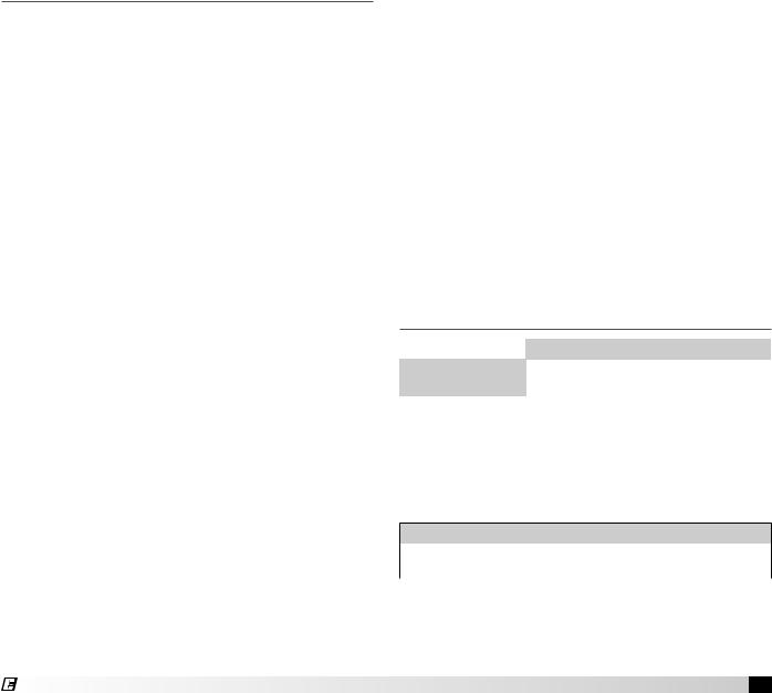
1. Install Hangers
Install threaded hangers from ceiling supports. When locating hangers, allow enough room to open access panel(s). Two nuts must be used on the end of each threaded hanger. Ceiling supports are supplied by others.
2. Install Unit
Raise the unit into place. Using two nuts per hanger, fasten the unit supports to hangers under the unit. Appropriate unit supports, such as the optional Greenheck hanging bracket kit or c-channel and angle iron (supplied by others) should be used.
Using self tapping screws, attach ductwork to unit. In order to prevent the unit from swinging and to provide a safe environment for service and maintenance, additional measures must be taken to secure the unit in all directions.
Ceiling Supports |
Ductwork |
|

 Hangers
Unit Supports 
Indoor Mounting
NOTE
Two nuts must be used on each end of each threaded hanging rod for proper support.
WARNING
All factory provided lifting lugs must be used when lifting any unit. Failure to comply with this safety precaution could result in property damage, serious injury or death.
NOTE
Good duct practices should be followed for all ductwork. Ductwork should be installed in
accordance with SMACNA and AMCA guidelines, NFPA 96 and any local codes. Reference the CAPS submittal for duct sizes.
3. Install Vent Piping
Refer to the Indoor Venting Instructions. Refer to your unit submittal to determine the correct venting option.
NOTE
Vent piping is supplied by others and not supplied by Greenheck.
4 Model IG / IGX Make-Up Air
Installation of Arrangement DB / HZ
1. Install Curb and/or Equipment Support(s)
Position curb/equipment support(s) on the roof (reference the CAPS submittal for placement of curb/ equipment support(s) in relation to the unit). Verify that unit supports are level, shim if necessary. Attach curb to roof and flash into place. Attach the equipment support(s) to the roof, remove metal cover, flash to wooden nailer and reinstall cover.
Roof Curb
Metal Cover
Equipment
 Support
Roof Curb and Equipment Support
2. Install Ductwork
Good duct practices should be followed for all
ductwork. All ductwork should be installed in |
||
accordance with |
Supply Air Ductwork |
|
SMACNA and |
||
(Arrangement DB only) |
||
AMCA guidelines, |
|
|
NFPA 96 and |
|
|
all local codes. |
|
|
Reference the |
|
|
CAPS submittal |
Ductwork |
|
for ductwork sizes. |
||
NOTE
The use of a duct adapter is recommended on a downblast (DB) arrangement to align the ductwork with the supply unit. The duct adapter is only a guide and is not to be used as support for the ductwork.
3. Apply Sealant
Apply an appropriate sealant around the perimeter of the curb and duct adapter(s) to isolate fan vibration and prevent water penetration.
4. Install Unit
Use a crane and a set of
spreader bars hooked to the
factory lifting lugs to lift and center the unit on the curb/equipment support(s).
Use self-tapping |
|
sheet metal |
|
screws to fasten |
|
the unit to the |
|
curb/equipment |
|
support(s). |
Setting Unit |
|
®
NOTE
The use of all lifting lugs and a set of spreader bars is mandatory when lifting the unit.
NOTE
Some units come with the weatherhood attached and step 5 may not apply.
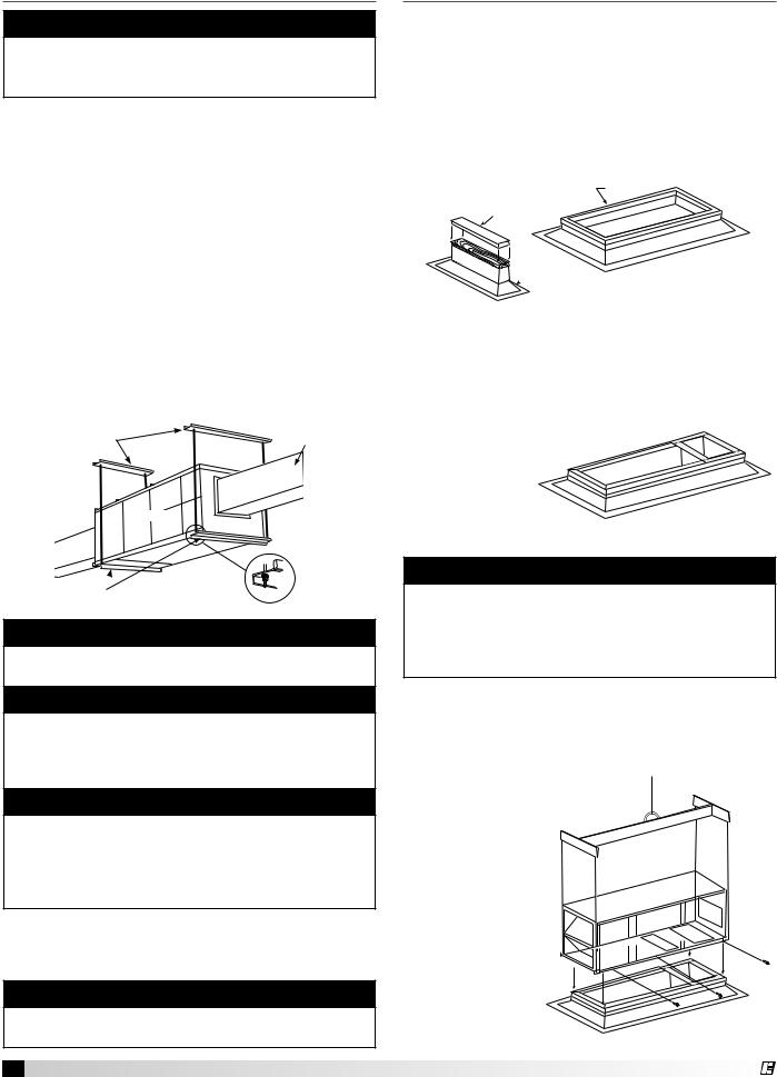
5. Assemble and Attach Weatherhood
The weatherhood can now be assembled and attached to the unit. Detailed assembly instructions can be found with the weatherhood. If the optional evaporative cooling module was selected, this step does not apply, refer to the installation instructions for the Optional Evaporative Cooling Module section, page 7.
6. Seal Weatherhood Seam
Using an appropriate sealant, seal the seam between the weatherhood and the unit.
Complete Rooftop Installation
®
Installation of Roof Mounted Unit
Arrangement DBC
1. Install Curb/Equipment Support(s)
Position curb/equipment support(s) on the roof (reference the CAPS submittal for placement of curb/ equipment support(s) in relation to the unit). Verify that all unit supports are level, shim if necessary. Attach curb to roof and flash into place. Attach the equipment support(s) to the roof, remove metal cover, flash to wooden nailer and reinstall cover.
Roof Curb
Metal Cover
Equipment
 Support
Roof Curb and Equipment Support
NOTE
Refer to Outdoor Venting instructions when locating the unit.
2. Install Combination Extension
Install combination extension |
Exhaust |
1 inch |
|
over curb. Lag into place |
|
||
|
|
||
|
|
Inside |
|
using wood screws. |
Supply |
|
Flange |
|
|
||
Locate the extension |
|
|
|
|
|
|
|
so the tall vented |
|
|
|
side is over the |
|
|
|
exhaust |
|
|
|
opening. |
|
|
|
5

Installation of Roof Mounted Unit Arrangement DBC, continued
4. Apply Sealant
Apply an appropriate sealant around the perimeter of the curb and duct adapter(s) to isolate fan vibration and prevent water penetration.
Exhaust Duct Installed
Sealant
Supply Duct with
Duct Adapter Installed
Sealing Ductwork
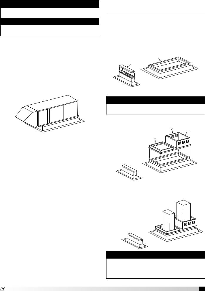
5. Install Exhaust Fan
Fasten exhaust fan to curb extension with self-tapping sheet metal screws.
Model CUBE
Exhaust Fan
Installing Exhaust Fan
Note
Installing the exhaust fan prior to the supply unit will allow for easier installation of options.
6. Install Exhaust Options
Install optional Greenheck hinge kit with restraining cables and grease trap with drain connection.
Note
NFPA 96 requires that the exhaust fan be hinged.
6 Model IG / IGX Make-Up Air
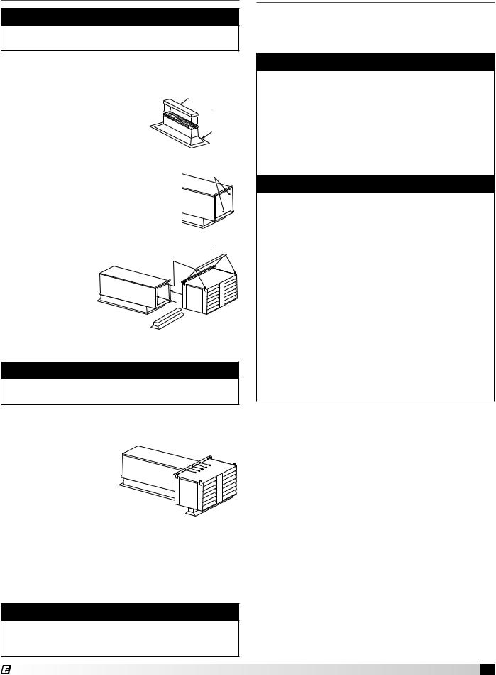
7. Install Supply Unit
Use a crane and a set of spreader bars hooked to the factory lifting lugs to lift and center the unit on the extension/equipment support(s).
Use self-tapping sheet metal screws to fasten the unit to the extension/equipment support(s).
Installing Supply Unit
Note
The use of all lifting lugs and a set of spreader bars is mandatory when lifting unit.
Note
Be sure to complete the outdoor venting installation instructions.
Note
Some units come with the weatherhood attached and step 8 may not apply.
8. Assemble and Attach Weatherhood
The weatherhood can now be assembled and/or attached to the unit. Detailed assembly instructions can be found with the weatherhood. If the optional evaporative cooling module was selected, this step does not apply, refer to the Installation Instructions for the Optional Evaporative Cooling Module section, page 7.
9. Seal Weatherhood Seam
Using an appropriate sealant, seal the seam between the weatherhood and the unit.
Complete Combination Installation
®
Installation of Venting for Outdoor Units
1. Follow Guidelines
All of the following guidelines must be followed when installing the unit.
Warning
Do not install units in locations where flue products can be drawn into adjacent building openings such as windows, fresh air intakes, etc. Distance from vent terminal to adjacent public walkways, adjacent buildings, operable windows, and building openings shall conform with the local codes. In the absence of local codes, installation shall conform with the National Fuel Gas Code, ANSI Z223.1, or the CAN/ CGA B-149 Installation Codes.
Warning
The following guidelines must be followed for all outdoor units:
1.Building materials that will be affected by flue gases should be protected.
2.Maintain minimum horizontal clearance of 4 feet from electric meters, gas meters, regulators, and relief equipment. In Canada, the minimum clearance is 6 feet.
3.The combustion blower discharge on outdoor units must be located a minimum of 42 inches from any combustible materials.
4.Do not modify or obstruct the combustion air inlet cover or the combustion blower weatherhood.
5.Do not add vents other than those supplied by the manufacturer.
6.During the winter, keep the unit clear of snow to prevent any blockage of the combustion venting.
2.Install Stack (Optional)
Clearance may require an exhaust stack. Install an exhaust stack as needed to the exhaust connection on the unit. Install a vent terminal on the exhaust pipe.
Model IG / IGX Make-Up Air 7
Installation of Venting for Indoor Units
Warning
The following guidelines must be followed for all indoor units:
1.Installation of venting must conform with local building codes. In the absence of local codes, installation must conform with the National Fuel Gas Code, ANSI Z223.1 or in Canada, CAN/ CGA-B149 installations codes.
2.For the exhaust pipe, use pipe approved for a category III appliance or single wall, 26 gauge or heavier galvanized vent pipe. The piping is required to be gas tight by ANSI.
3.For the combustion air pipe on separated combustion units, sealed single-wall galvanized air pipe is recommended.
4.The joints must be sealed with a metallic tape or Silastic™ suitable for temperatures up to 350°F.
5.A minimum of 12 inches of straight vent pipe is recommended after the exhaust connection and before any elbows.
6.Vertical combustion air pipes should be fitted with a tee, drip leg and clean-out cap to prevent any moisture in the combustion air pipe from entering the unit.
7.To reduce condensation, insulate any vent runs greater than 5 feet.
8.All vent pipe connections should be made with at least three corrosion resistant sheet metal screws.
9.Refer to the National Fuel Gas Code for additional piping guidelines.
Note
Vent piping is supplied by others and not supplied by Greenheck.
Note
The drip leg should be cleaned out periodically during the heating season.
Note
Clearances from combustible material for indoor units are determined by the National Fuel Gas Code and/or other local codes.
Venting Methods
There are three venting methods for indoor mounted units. For each method, the units can be vented horizontally through an exterior wall or vertically through the roof. Specific venting instructions are provided for each method and shown in the following pages. Construct the vent system as shown in these instructions. Refer to your unit specific submittal to determine the applicable venting option.
The venting method options are:
Standard Indoor Venting
•uses building air for combustion
•vents exhaust to outdoors
•one exterior roof or wall penetration
Separated Combustion Concentric Venting
•uses outside air for combustion
•vents exhaust to outdoors
•one exterior roof or wall penetration
Separated Combustion 2-Pipe Venting
•uses outside air for combustion
•vents exhaust to outdoors
•two exterior roof or wall penetrations
Note
For each method, the units can be vented horizontally through an exterior wall or vertically through the roof. Refer to the specific venting instructions for your unit. Construct the vent system as shown in these instructions.
8 Model IG / IGX Make-Up Air
®
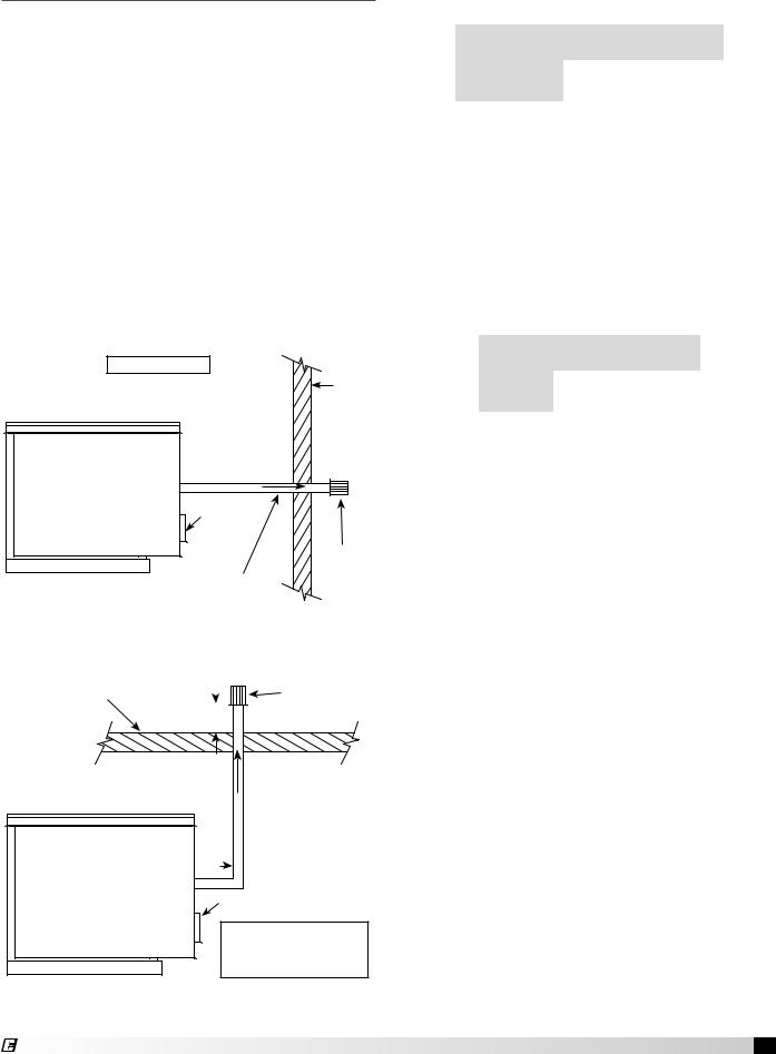
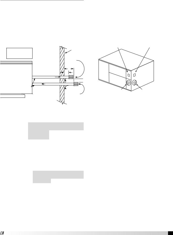
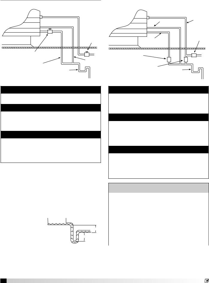
Installation of Standard Indoor
Venting
Standard Indoor Venting uses one penetration through an exterior wall or roof for venting the flue exhaust. The combustion air is supplied from the air inside the building. Units must not be installed in a potentially explosive, flammable, or corrosive atmosphere. To prevent premature heat exchanger failure, do not locate unit where chlorinated, halogenated or acid vapors are present.
When units are installed in tightly sealed buildings, provisions should be made to supply an adequate amount of infiltration air from the outside. The rule of thumb is that an opening of one square inch should be provided for every 1000 BTUs per hour of input rating.
Vent terminals must be used. Construct the vent system as shown in the drawings. Reference the Vent Pipe Diameter table and Exhaust Vent Pipe table for additional details.
A = 12 in. minimum
Exterior
Wall
 A
A 
EXHAUST
Air Inlet
Exhaust
Vent
Pitch vent pipe Terminal downward from
furnace
1/4 inch per foot
Standard Indoor Venting - Horizontal
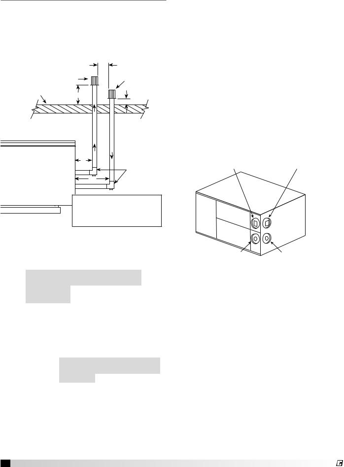
Roof Line |
|
|
Exhaust Vent |
|
|
|
Terminal |
|
|
|
|
|
B |
||
EXHAUST
 A
A
Air Inlet
A = 12 inch minimum
B = 12 inch minimum but should size according to expected snow depth
Standard Indoor Venting - Vertical
Vent Pipe Diameter
Select the vent pipe diameter. Use only the specified pipe diameter.
Furnace Size |
Exhaust Pipe Diameter |
(MBH) |
(inches) |
|
|
75 - 175 |
4 |
|
|
200 - 400 |
6 |
|
|
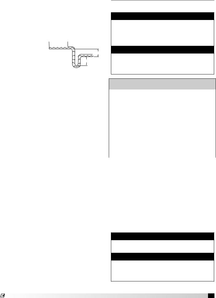
Installing Exhaust Vent Pipe
Install the vent pipe with a minimum downward slope (from the unit) of 1/4-inch per foot (horizontal venting only). Securely suspend the pipe from overhead structures at points no greater than 3 feet apart.
The minimum vent length is 5 feet for horizontal and 10 feet for vertical. The maximum vent length is 70 feet. The total equivalent vent length must include elbows. The equivalent length of a 4 inch elbow is 6 feet and the equivalent length of a 6 inch elbow is 10 feet. Attach the vent terminal to the end of the exhaust pipe.
Vent |
Minimum |
Maximum |
Length |
(feet) |
(feet) |
|
|
|
Horizontal |
5 |
70 |
|
|
|
Vertical |
10 |
70 |
|
|
|
Model IG / IGX Make-Up Air 9
®
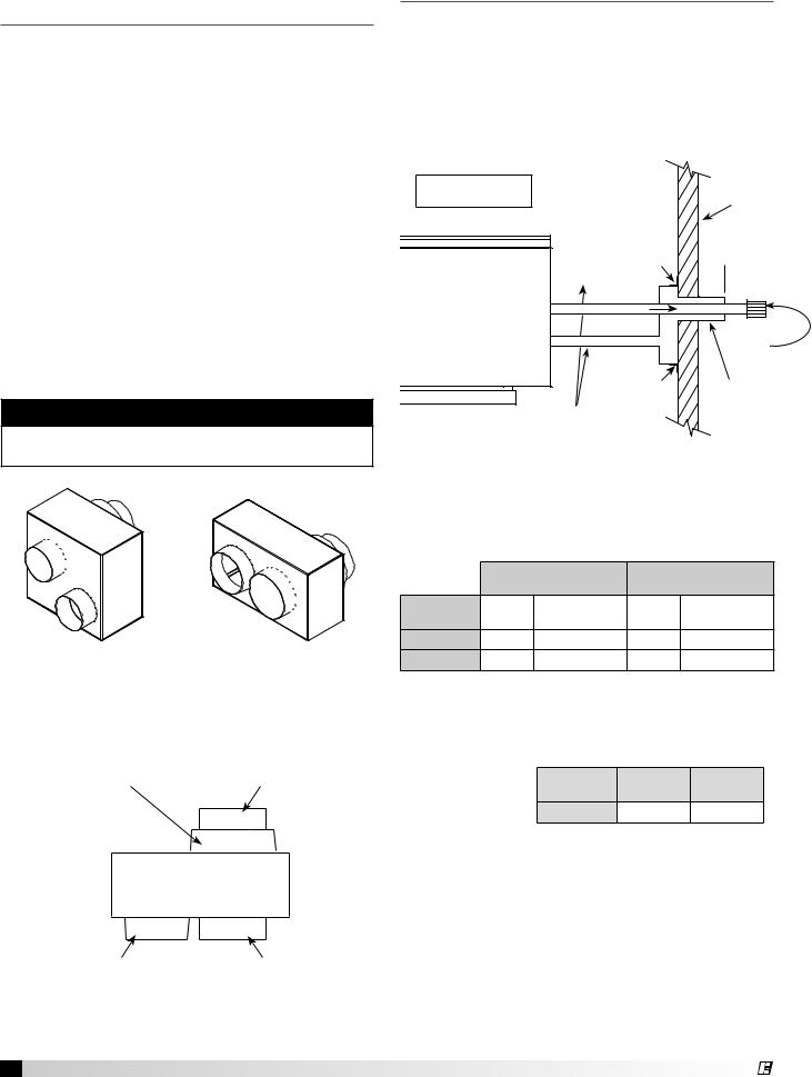
Installation of Concentric Venting (General)
Concentric venting allows the exhaust pipe and combustion air pipe to pass through a single hole in the roof or wall of the building. A concentric venting adapter (CVA) is required for concentric venting.
The concentric venting adapter is designed for indoor installations and should never be installed on the exterior of the building.
The exhaust pipe must terminate with the vent terminal. For horizontal venting, the combustion air pipe must terminate with the combustion air guard. For vertical venting, the combustion air pipe must terminate with the inlet terminal. Depending on what was ordered, one of these vent terminals will be provided in the optional venting kit along with the concentric venting adapter (CVA).
If venting vertically through the roof, refer to the vertical concentric venting instructions. If venting horizontally through the wall, refer to the horizontal concentric venting instructions.
note
Vent piping is supplied by others and not supplied by Greenheck.
CVA-4 |
CVA-6 |
4-inch Concentric |
6-inch Concentric |
Venting Adapter |
Venting Adapter |
Combustion Air Connection |
Exhaust Connection |
Concentric Side |
Concentric Side |
CVA
Combustion Air Connection |
Exhaust Connection |
Non-Concentric Side |
Non-Concentric Side |
Top View
10 Model IG / IGX Make-Up Air
Concentric Venting – Horizontal
Refer to the diagram below for venting on horizontal concentric systems. Maintain at least 12 inches from the combustion air inlet guard to the exhaust vent terminal (Dim. B). To prevent water from running into the combustion air pipe and to allow for easy installation of the combustion air inlet guard, the combustion air pipe must terminate at least 2 inches from the exterior surface of the outside wall (Dim. A).
A = 2 inch minimum
B = 12 inch minimum
Mounting
Bracket
EXHAUST
 COMBUSTION AIR
Mounting
Bracket
Pitch vent pipe downward from furnace 1/4 inch per foot
Exterior
Wall
 A B
A B 
Exhaust
Vent
Terminal
Combustion
Air Inlet
Guard
Vent Connection Diameter
Vent terminals must be used (one vent terminal included with each furnace). Construct the vent system as shown in the drawings and refer to the table for the correct vent connection diameters.
|
Non-Concentric Vent |
Concentric Vent |
||
|
Connection Diameter |
Connection Diameter |
||
Furnace Size |
Exhaust |
Combustion Air |
Exhaust |
Combustion Air |
(MBH) |
(inches) |
(inches) |
(inches) |
(inches) |
75-175 |
4 |
4 |
4 |
6 |
200-400 |
6 |
6 |
6 |
8 |
Vent Length
Refer to table for minimum and maximum vent lengths. The total equivalent vent length must include elbows. The equivalent length of a 4 inch elbow is
6 feet and the |
Vent |
Minimum |
Maximum |
|
equivalent length |
||||
Length |
(feet) |
(feet) |
||
of a 6 inch elbow |
||||
Horizontal |
5 |
70 |
||
is 10 feet. |
||||
|
|
|
1. Determine Venting Location
Determine the location of the concentric venting adapter (CVA) based on any clearances that must be maintained (follow all codes referenced in these instructions).
2. Attach Mounting Brackets
Attach field supplied, corrosion resistant, mounting brackets to the CVA using corrosion resistant sheet metal screws.
®
3. Install Exhaust Pipe
Slide the exhaust pipe through the CVA. Provide enough exhaust piping to pass through the wall (or floor) and provide the minimum clearance of 12 inches between the exhaust pipe termination and the combustion air intake. With all required clearances satisfied, attach the exhaust pipe to the CVA.
Exhaust Connection |
Exhaust Connection |
(Model IGX) |
(Model IG) |
Intake End

 Discharge End
Combustion Air Connection |
Combustion Air Connection |
(Model IGX) |
(Model IG) |
4. Install Combustion Air Pipe
Attach a field supplied combustion air pipe to the concentric side of the CVA.
Be sure to provide enough combustion air piping to pass through the wall and provide the minimum clearance of 2 inches between the combustion air intake and the exterior surface of the outside wall.
Be sure to maintain the minimum clearance of
12 inches between the exhaust pipe termination and the combustion air intake.
5. Install CVA Assembly
Place the CVA assembly through the wall and verify that all minimum clearance requirements as specified in these instructions are met. Secure the CVA assembly to the wall with corrosion resistant sheet metal screws through the mounting brackets.
6. Attach CVA Assembly to Unit
Attach the exhaust pipe to the unit’s combustion exhaust. Using an additional combustion air pipe, connect the unit’s combustion air supply intake to the combustion air connection on the CVA.
7. Install Combustion Air Inlet Guard and Exhaust Vent Terminal
Slide the combustion air inlet guard over the exhaust pipe and fasten it to the combustion air pipe. Attach the exhaust vent terminal to the discharge end of the exhaust piping on the outside of the building.
8. Seal Opening
Seal the opening between the wall and the air intake pipe using an appropriate method.
Concentric Venting – Vertical
Refer to the diagram below for venting on vertical concentric systems. Maintain at least 12 inches between the top of the combustion air inlet terminals and the bottom of the exhaust terminal. (Dim. B).
The bottom of the combustion air intake pipe must terminate above the snow line or at least 12 inches above the roof, whichever is greater.
A tee with cleanout must be provided on the combustion air and exhaust pipe to prevent debris from entering the heat exchanger.
A = 12 inch minimum but should size according to expected snow depth
B = 12 inch minimum C = 12 inch minimum
B |
|
Roofline |
|
A |
|
Mounting |
|
Bracket |
EXHAUST |
|
|
C |
|
|
C |
Exhaust Vent
Terminal
Combustion Air
Inlet Terminal
AIR |
|
|
|
Mounting |
|||
COMBUSTION |
|||
Bracket |
|||
|
|||
Tee with drip leg and clean-out cap
Vent Connection Diameter
Vent terminals must be used. Construct the vent system as shown in the drawings and refer to the table for the correct vent connection diameters.
|
Non-Concentric Vent |
Concentric Vent |
||
|
Connection Diameter |
Connection Diameter |
||
|
|
|
|
|
Furnace Size |
Exhaust |
Combustion Air |
Exhaust |
Combustion Air |
(MBH) |
(inches) |
(inches) |
(inches) |
(inches) |
|
|
|
|
|
75-175 |
4 |
4 |
4 |
6 |
|
|
|
|
|
200-400 |
6 |
6 |
6 |
8 |
|
|
|
|
|
Vent Length
Refer to table for minimum and maximum vent lengths. The total equivalent vent length must include elbows. The equivalent length of a 4 inch elbow is
6 feet and the |
|
|
|
|
Vent |
Minimum |
Maximum |
||
equivalent length |
||||
Length |
(feet) |
(feet) |
||
of a 6 inch elbow |
|
|
|
|
Vertical |
10 |
70 |
||
is 10 feet. |
||||
|
|
|
||
|
|
|
1. Determine Venting Location
Determine the location of the concentric venting adapter (CVA) based on any clearances that must be maintained (follow all codes referenced in these instructions).
Model IG / IGX Make-Up Air 11
®
2. Attach Mounting Brackets
Attach field supplied, corrosion resistant, mounting brackets to the CVA using corrosion resistant sheet metal screws.
3. Install Exhaust Pipe
Slide the exhaust pipe through the CVA. Provide enough exhaust piping to pass through the roof and provide the minimum clearance of 12 inches between the exhaust pipe termination and the combustion air intake. With all required clearances satisfied, attach the exhaust pipe to the CVA.
Exhaust Connection |
Exhaust Connection |
(Model IGX) |
(Model IG) |
Intake End

 Discharge End
7. Install Combustion Air Inlet Guard and Exhaust Vent Terminal
Slide the combustion air terminal over the vent pipe and fasten it to the combustion air pipe. Attach the exhaust vent terminal to the discharge end of the exhaust piping.
8. Seal Opening
Seal the opening between the roofs and the air intake pipe using an appropriate method.
Combustion Air Connection |
Combustion Air Connection |
(Model IGX) |
(Model IG) |
4. Install Combustion Air Pipe
Attach a field supplied combustion air pipe to the concentric side of the CVA.
Be sure to provide enough combustion air piping to pass through the roof and provide the minimum clearance of 12 inches between the combustion air intake and the exterior surface of the roof. This
clearance may need to be increased to allow for snow accumulation.
Be sure to maintain the minimum clearance of
12 inches between the exhaust pipe termination and the combustion air intake.
5. Install CVA Assembly
Place the CVA assembly through the roof and verify that all minimum clearance requirements as specified in these instructions are met. Secure the CVA assembly to the ceiling with corrosion resistant sheet metal screws through the mounting brackets.
6. Attach CVA Assembly to Unit
Attach the exhaust pipe to the unit’s combustion exhaust. Using an additional combustion air pipe, connect the unit’s combustion air supply intake to the combustion air connection on the CVA.
Be sure to include the required tee’s with drip legs and clean-outs.
12 Model IG / IGX Make-Up Air
®
Installation of Two Pipe Venting –
Horizontal
Refer to the diagram below for venting on horizontal concentric systems. Maintain at least 12 inches of clearance between the exhaust pipe termination and the exterior surface of the exterior wall (Dim. A).
The combustion air pipe must be a minimum of 12 inches from the exhaust pipe and 24 inches from the exterior surface of the outside wall (Dim. B).
A minimum of 1 inch and a maximum of 48 inches of building wall thickness is required for separated combustion vent pipe.
A = 12 inch minimum |
Exterior |
|
Wall |
||
B = 24 inch minimum |
||
|
||
C = 12 inch minimum |
Exhaust |
|
|
||
|
Vent |
|
|
Terminal |
|
|
B |
|
|
A |
|
|
EXHAUST |
|
Pitch vent pipe |
C |
|
COMBUSTION AIR |
||
downward from |
||
|
furnace |
|
Two (2) Field |
|
Combustion |
1/4 inch per foot |
|
|
||
|
|
Supplied Support |
|
Air Inlet |
|
|
|
||
|
|
Brackets |
|
Terminal |
Vent Connection Diameter
Vent terminals must be used. The optional vent kit includes two terminals. Construct the vent system as
shown in the |
|
|
|
|
drawings and |
Furnace Size |
Exhaust |
Combustion |
|
refer to the table |
(MBH) |
(inches) |
(inches) |
|
75 - 175 |
4 |
6 |
||
for the correct |
||||
vent connection |
200 - 400 |
6 |
8 |
|
diameters. |
|
|
|
Vent Length
Refer to table for minimum and maximum vent lengths. The minimum vent length is 5 feet and the
maximum vent length is 50 feet. The total equivalent |
||||
vent length must include elbows. The equivalent |
||||
length of a 4 inch |
|
|
|
|
elbow is 6 feet |
Vent |
Minimum |
Maximum |
|
and the equivalent |
Length |
(feet) |
(feet) |
|
Horizontal |
5 |
50 |
||
length of a 6 inch |
||||
elbow is 10 feet.
2. Install Combustion Air Pipe
Run a combustion air pipe from the unit’s combustion air intake through the exterior wall to the outdoors. The combustion air pipe must terminate at least 12 inches from the combustion vent pipe and 24 inches from the exterior surface of the outside wall. Attach the combustion air inlet guard to the end of the combustion air pipe. Using field supplied mounting brackets, support the combustion air pipe as needed.
3. Seal Wall Openings
Using an appropriate method, seal the wall openings around the piping.
Exhaust Connection |
Exhaust Connection |
(Model IGX) |
(Model IG) |
Intake End

 Discharge End
Combustion Air Connection |
Combustion Air Connection |
(Model IGX) |
(Model IG) |
1. Install Exhaust Pipe
Run an exhaust pipe from the unit’s combustion exhaust through the exterior wall to the outdoors. The exhaust pipe must terminate at least 12 inches from the outside surface of the outside wall. Attach exhaust vent terminal to the end of the exhaust pipe. Using field supplied mounting brackets, support the exhaust pipe as needed.
Model IG / IGX Make-Up Air 13
®
Installation of Two Pipe Venting –
Vertical
Refer to the diagram below for venting on vertical concentric systems. The combustion air pipe must terminate at least 12 inches above the roof. This clearance may need to be increased to accommodate for snow accumulation. The exhaust must terminate at least 12 inches above and 12 inches horizontally from the combustion air inlet.
|
|
C |
Exhaust Vent |
Combustion |
|
|
Terminal |
Air Inlet |
|
|
Terminal |
Roofline |
B |
|
|
|
|
|
|
A |
|
EXHAUST |
COMBUSTION AIR |
|
D |
|
|
|
Tee with drip leg |
|
D |
and cleanout cap |
|
|
|
|
A = 12 inch minimum but should size |
|
|
according to expected snow depth |
|
B = 24 inch minimum
C = 12 inch minimum
D = 12 inch minimum
Vent Connection Diameter
Vent terminals must be used. Construct the vent system as shown in the drawings and refer to the table for the correct vent connection diameters.
Furnace Size |
Exhaust |
Combustion |
(MBH) |
(inches) |
(inches) |
|
|
|
75 - 175 |
4 |
6 |
|
|
|
200 - 400 |
6 |
8 |
|
|
|
Vent Length
Refer to table for minimum and maximum vent lengths. The minimum vent length is 10 feet and the maximum vent length is 70 feet. The total equivalent vent length must include elbows. The equivalent length of a 4 inch
elbow is 6 feet |
Vent |
Minimum |
Maximum |
and the equivalent |
Length |
(feet) |
(feet) |
length of a 6 inch |
Vertical |
10 |
70 |
elbow is 10 feet. |
|
|
|
1. Install Exhaust Pipe
Run an exhaust pipe from the unit’s combustion exhaust through the roof to the outdoors. The exhaust pipe must terminate at least 12 inches above the outside surface of the roof. This clearance may need to be increased to accommodate snow accumulation. Attach the exhaust vent terminal to the end of the exhaust pipe.
2. Install Combustion Air Pipe
Run a combustion air pipe from the unit’s combustion air intake through the roof to the outdoors. The combustion air pipe must terminate at least 12 inches horizontally and vertically from the combustion exhaust pipe and at least 24 inches from the exterior surface of the roof. These clearances may need to be increased to accommodate for expected snow accumulation. Attach the combustion air terminal to the end of the combustion air pipe.
3. Seal Roof Penetration
Using an appropriate method, seal the roof openings around the vent pipes.
Exhaust Connection |
Exhaust Connection |
(Model IGX) |
(Model IG) |
Intake End
|
Discharge End |
Combustion Air Connection |
Combustion Air Connection |
(Model IGX) |
(Model IG) |
14 Model IG / IGX Make-Up Air
®
Installation - Electrical Wiring
IMPORTANT
Before connecting power to the unit, read and understand the following instructions and wiring diagrams. Complete wiring diagrams are attached on the inside of the control center door(s).
IMPORTANT
All wiring should be done in accordance with the latest edition of the National Electric Code ANSI/ NFPA-70 and any local codes that may apply. In Canada, wiring should be done in accordance with the Canadian Electrical Code.
caution
If replacement wire is required, it must have a temperature rating of at least 105ºC, except for energy cut-off or sensor lead wire which must be rated to 150ºC.
IMPORTANT
The equipment must be properly grounded. Any wiring running through the unit in the airstream must be protected by metal conduit, metal clad cable or raceways.
danger
High voltage electrical input is needed for this equipment. This work should be performed by a qualified electrician.
caution
Any wiring deviations may result in personal injury or property damage. Greenheck is not responsible for any damage to, or failure of the unit caused by incorrect final wiring.
IMPORTANT
Greenheck’s standard control voltage is 24 VAC. Control wire resistance should not exceed 0.75 ohms (approximately 285 feet total length for 14 gauge wire; 455 feet total length for 12 gauge wire). If the resistance exceeds 0.75 ohms an industrial-style, plug-in relay should be wired in place of the remote switch. The relay must be rated for at least 5 amps and have a 24 VAC coil. Failure to comply with these guidelines may cause motor starters to chatter or not pull in, resulting in contactor failures and/or motor failures.
®
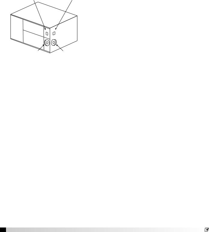
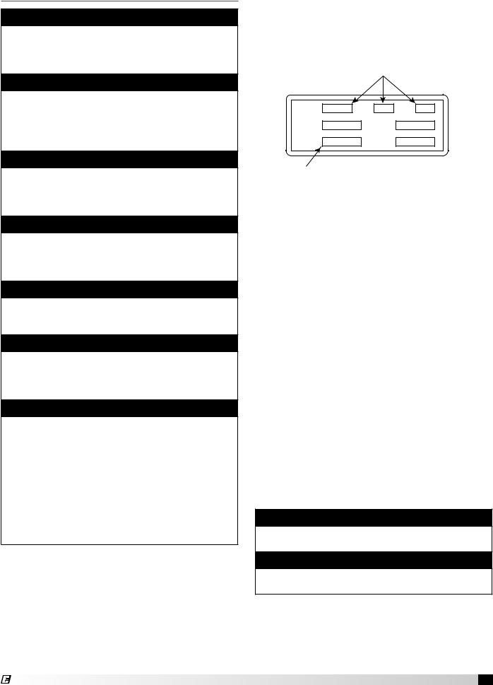
1. Determine the Size of the Main Power Lines
The unit’s nameplate states the voltage and the unit’s total MCA. The main power lines to the unit should be sized accordingly. The nameplate is located on the outside of the unit on the control panel side.
Voltage, Hertz, Phase
VOLTS |
HZ |
PH |
SUP HP |
EXH HP |
|
MCA |
MOP |
|
Unit’s Total MCA
Electrical Nameplate
2. Provide the Opening(s) for the Electrical Connections
Electrical openings vary by unit size and arrangement and are field supplied.
3. Connect the Main Power
Connect the main power lines to the disconnect switch and main grounding lug(s). Torque field connections to 20 in.-lbs.
4. Wire the Optional Convenience Outlet
The convenience outlet requires a separate 115V power supply circuit. The circuit must include short circuit protection which may need to be supplied by others.
5. Wire the Optional Accessories
Reference the ladder diagram on the inside of the control center door for correct wiring of the following accessories:
• Selectra Stat |
• Dirty Filter Indicator |
• Room Override |
• TSCP |
• Blower Switch |
• KSCP |
• Heat Switch |
• Economizer Activator |
• Indicating Lights |
• Room Stat |
note
Wiring to the Selectra Stat or room override should be in separate conduit or run with shielded cable.
note
The TSCP and KSCP remote panels have number- to-number wiring.
Model IG / IGX Make-Up Air 15

6. Wire the Evaporative Cooler (optional)
Reference the ladder diagram on the inside of the control center door for correct wiring of the pump and the optional water valves.
note
Large evaporative coolers may require a separate power supply.
7. Install Economizer Sensors (optional)
All economizer options (EC) require an outdoor air temperature or enthalpy sensor to be field installed inside of the weatherhood and field wired to terminals SO+ and SO- on the economizer.
Economizer options EC-3 and EC-4 require an outdoor air temperature or enthalpy sensor to be field installed in the return air duct and field wired to terminals SR+ and SR- on the economizer.
The sensors are provided by the factory and ship with the unit.
8. Install Discharge Air Sensor (optional)
For units with 8:1, 16:1 or 24:1 staged turndown, install the discharge air sensor at least three duct diameters downstream of the heat exchanger. The discharge air sensor can be found in the unit’s control center.
9. Install DDC Interface (Optional)
Some units may use an external signal from a building management system to control the dampers and/or discharge air temperature. Reference the unit ladder diagram for the correct wiring.
16 Model IG / IGX Make-Up Air
®
Installation of Gas Piping
IMPORTANT
All gas piping must be installed in accordance with the latest edition of the National Fuel Gas Code ANSI/Z223.1 and any local codes that may apply. In Canada, the equipment shall be installed in accordance with the Installation Code for Gas
Burning Appliances and Equipment (CGA B149) and Provincial Regulations for the class. Authorities having jurisdiction should be consulted before installations are made.
IMPORTANT
All piping should be clean and free of any foreign material. Foreign material entering the gas train can cause damage.
Warning
All components of this or any other gas fired heating unit must be leak tested prior to placing the unit into operation. A soap and water solution should be used to perform this test. NEVER test for gas leaks with an open flame.
IMPORTANT
Do NOT connect the unit to gas types other than what is specified and do NOT connect the unit to gas pressures that are outside of the pressure range shown on the label.
Warning
When leak testing pressures equal to or less than 14 in. wc (3.5 kPa), first close the field-installed shutoff valve to isolate the unit from the gas supply line.
Note
When connecting the gas supply, the length of the run must be considered in determining the pipe size to avoid excessive pressure drop. Refer to a Gas Engineer’s Handbook for gas pipe capacities.
Note
Each furnace has a single 3/4-inch connection.
®
1. Determine the Supply Gas Requirements
The unit’s nameplate states the requirements for the gas being supplied to the unit.
Minimum gas pressure for maximum output
MAX BTU/HR
BTU/H MAX
NORMAL MANIFOLD
PRESSURE “W.C. PRESSION DÕADMISSION
NORMALE
MIN GAS
PRESSURE “W.C. PRESSION DE GAZ
“W.C.
MIN BTU/HR
BTU/H MIN
MIN GAS PRESSURE FOR MAX OUTPUT PRESSION DE GAZ MIN POUR PUISSANCE MAX
MAX GAS
PRESSURE PRESSION DE GAZ MAX
“W.C.
PSI
|
|
|
|
DESIGN DT |
|
TYPE OF GAS |
|
|
|
DT NORMALE |
|
|
|
|
|
F |
|
NATURE DU GAZ |
|
|
|
|
|
|
|
|
|
|
|
|
|
|
|
|
|
EQUIPPED FOR |
|
AGAINST |
|
|
EXTERNAL STATIC PRESSURE |
|
|
|
|||
|
SCFM |
|
|
“W.C. |
|
CONCU POUR |
|
CONTE |
|
|
PRESSION STATIQUE EXTERIEURE |
|
|
|
|
|
|
Type of gas |
Maximum gas pressure |
|
Indirect Gas Nameplate |
2. Install Additional Regulator if Required
When the supply gas pressure exceeds the maximum gas pressure shown on the unit’s nameplate, an additional regulator (by others) is required to reduce
the pressure. The regulator |
|
|
|
Supply Gas Pressure Range |
|||
must have a listed leak |
(inches wc) |
||
limiting device or it must |
Minimum |
Maximum |
|
be vented to |
Natural |
6 |
14 |
the outdoors. |
|
|
|
LP |
10 |
14 |
|
|
|
|
|
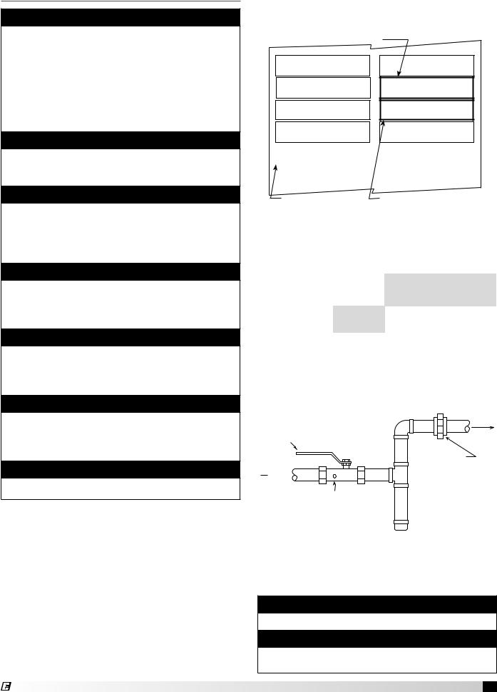
3. Connect the Supply Gas Line
A manual shut off valve (gas cock), 1/8 inch plugged test port and 6 inch drip leg must be installed prior to the gas train. The valve and the test port must be accessible for the connection of a test gauge. Supply
gas connections must be made by a qualified installer and are not furnished by
Greenheck.
Gas Cock
Ground Joint Union
From
Gas 
Supply
1/8 in. Plugged Tap
 6 in. Trap
Supply Gas Line
4. Test the System for Leaks
Check both the supply lines and the factory piping for leaks. Apply a soap and water solution to all piping and watch for bubbling which indicates a leak.
Warning
NEVER test for a gas leak with an open flame.
Warning
The factory piping has been checked for leaks, but should be rechecked due to shipping and installation.
Model IG / IGX Make-Up Air 17
Installation - Evaporative Cooler
Piping (optional)
Evaporative Cooling with Recirculating Pump
Supply
 Line
Line
Supply Line
Valve (Normally Closed)
Drain Line Valve
(Normally Open)
Overflow
Drain Line
Trap
Recirculating Evaporative Piping
Important
All supply solenoids, valves and all traps must be below the roofline or be otherwise protected from freezing.
Important
The supply line should be of adequate size and pressure to resupply the amount of water lost due to bleed-off and evaporation. The drain line should be the same size or larger than the supply line.
caution
Provisions must be taken to prevent damage to the evaporative cooling section during freezing conditions. The sump, drain lines and supply lines must be drained prior to freezing conditions or an alternate method must be used to protect the lines and media.
1. Install the Water Supply Line
Supply line opening requirements vary by unit size and arrangement and are field supplied. Connect the water supply line to the float valve through the supply line opening in the evaporative cooling unit. Install a manual shutoff valve in the supply line.
2. Install the Drain Line
Connect an unobstructed drain line to the drain and overflow connections on the evaporative cooler. A manual shut off valve (by others) is required for the evaporative cooler drain
line. A trap should be
used to prevent sewer gas from being drawn into the unit. Refer to Drain Trap drawing.
3. Check/Adjust Water Level
Check the water level in the sump tank. The water level should be above the pump intake and below the overflow. Adjust the float as needed to achieve the proper water level.
18 Model IG / IGX Make-Up Air
Evaporative Cooling with Auto Drain and Fill
Sump Overflow |
Supply |
Line |
|
|
VALVE A |
|
Supply Solenoid |
Sump Drain |
(Normally Closed) |
|
VALVE C
Sump Drain Solenoid
(Normally Open)
VALVE B
Supply Line Drain Solenoid Trap
(Normally Open)
Drain Line 
Auto Drain & Fill Evaporative Piping
Important
The supply line should be of adequate size and pressure to resupply the amount of water lost due to bleed-off and evaporation. The drain line should be the same size or larger than the supply line.
caution
All solenoids valves and traps must be installed below the roof to protect the supply water line from freezing. If they cannot be installed below the roof, an alternative method must be used to protect the lines from freezing.
Important
The supply solenoid (Valve A) is NOT the same as the drain solenoids (Valve B and Valve C). Make sure to use the proper solenoid for each location. Check your local code requirements for proper installation of this type of system.
Auto Drain & Flush Valves (when provided by Greenheck)
Assembly |
GFC |
ASCO™ |
Solenoid |
De-Energized |
|
|
|
Part |
Part |
Diameter |
Qty. |
||||
Number |
Number |
Number |
Type |
Position |
|
|
|
|
|
|
|
|
|
|
|
|
461262 |
8210G2 |
Supply |
Closed |
1/2 inch |
1 |
|
|
(12.7 mm) |
||||||
|
|
|
|
|
|
|
|
|
|
|
Supply |
|
1/4 inch |
|
|
852178 |
461263 |
8262G262 |
Line |
Open |
1 |
||
(6.35 mm) |
|||||||
|
|
|
Drain |
|
|
|
|
|
461264 |
8210G35 |
Sump |
Open |
3/4 inch |
1 |
|
|
Drain |
(19.05 mm) |
|||||
|
|
|
|
|
|
|
Part numbers subject to change.
1. Install the Water Supply Line
Supply line opening requirements vary by unit size and arrangement and are field supplied. Connect the water supply line to the float valve through the supply line
®
opening in the evaporative cooling unit. Install the 1/2 inch normally closed solenoid (Valve A) in the supply line as shown above. Install the 1/4 inch normally open solenoid (Valve B) between the supply line and the drain line as shown above.
2. Install the Drain Line
Connect an unobstructed drain line to the sump drain overflow connection. Install the 3/4 in. normally open solenoid (Valve C) between the sump drain connection and the drain line. A
trap should be used to prevent sewer gas from
being drawn into the unit. Refer to Drain Trap drawing.
3. Check/Adjust Water Level
Check the water level in the sump tank. The water level should be above the pump intake and below the overflow. Adjust the float as needed to achieve the proper water level.
Installation of Water WizardTM (optional)
Evaporative Cooling with the Water Wizard™
Note
The following instructions are provided for evaporative coolers equipped with the Water Wizard™ only. Additional instructions are provided for evaporative coolers equipped with the auto-drain and fill or bleed-off.
Warning
Disconnect and lock-out all power and gas before performing any maintenance or service to the unit. Failure to do so could result in serious injury or death and damage to equipment.
Water Wizard™ Valves (when provided by Greenheck)
Unit |
Assembly |
GFC |
ASCO™ |
Solenoid |
De- |
Diameter |
Qty. |
Model |
Number |
Part |
Part No. |
Type |
Energized |
||
No. |
Position |
|
|
||||
|
|
|
|
|
|
|
|
IGX - |
|
461262 |
8210G2 |
Supply |
Closed |
1/2 inch |
1 |
|
(12.7 mm) |
||||||
H12/H22 |
852370 |
|
|
|
|
|
|
|
|
Supply |
|
|
|
||
IGX - H32 |
|
|
|
1/2 inch |
|
||
|
383086 |
8210G34 |
Line |
Open |
1 |
||
(<9000 cfm) |
|
(12.7 mm) |
|||||
|
|
|
|
Drain |
|
|
|
|
|
|
|
|
|
|
|
|
|
|
|
|
|
|
|
|
|
383088 |
8210G9 |
Supply |
Closed |
3/4 inch |
1 |
IGX - H32 |
|
|
|
|
|
(19.05 mm) |
|
852371 |
|
|
Supply |
|
|
|
|
(≥9000 cfm) |
|
|
|
1/2 inch |
|
||
|
|
383086 |
8210G34 |
Line |
Open |
1 |
|
|
|
(12.7 mm) |
|||||
|
|
|
|
Drain |
|
|
|
Part numbers subject to change.
1. Install Normally Closed Supply Line/ Solenoid
Connect the water supply line to the manual supply valve in the unit. Install the supply solenoid in the supply line, upstream of the manual supply valve and below the roofline.
2. Install Normally Open Drain Line/ Solenoid
Connect the drain line to the supply line between the manual supply valve and the supply solenoid. Install a drain solenoid in the drain line, below the roof line. A trap should be installed in the drain line.
Note
Solenoid(s) may be provided by Greenheck (if ordered) or by others.
Caution
Any wiring deviations may result in personal injury or property damage. Greenheck is not responsible for any damage to, or failure of the unit caused by incorrect final wiring.
Model IG / IGX Make-Up Air 19
®
Installation of Water Wizard™, continued
To Media
|
Pressure |
Factory |
|
Gauge |
|
|
Installed |
|
|
Sump Drain |
|
|
|
|
|
Manual Supply |
|
|
Valve |
|
Roof |
Supply Solenoid |
|
Line |
(Normally Closed) |
|
Trap |
Supply Line Drain Solenoid |
Field |
|
(Normally Open) |
Installed |
Water Wizard™ Installation
3. Wire the Solenoid(s)
Wire the supply line solenoid and drain solenoid as shown on the unit’s wiring diagram in the control center.
4. Wire the Temperature Sensor
If the evaporative cooler shipped separate from the unit, the temperature sensor must be wired. The sensor wire is bundled inside the discharge end of the evaporative cooler. Wire the sensor wire to terminals AI2 and AIC on the terminal strip in the unit’s control center.
Note
The Water Wizard™ start-up must be completed for proper performance.
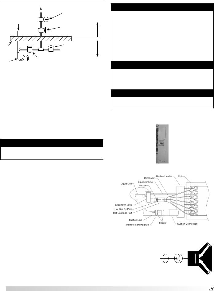
Installation - Direct Expansion (DX)
Coil Piping (optional)
Important
Guidelines for the installation of direct expansion cooling coils have been provided to insure proper performance and longevity of the coils. These are general guidelines that may have to be tailored to meet the specific requirements of any one job. As always, a qualified party or individual should
perform the installation and maintenance of any coil. Protective equipment such as safety glasses, steel toe boots and gloves are recommended during the installation and maintenance of the coil.
Important
All field brazing and welding should be performed using high quality materials and an inert gas purge (such as nitrogen) to reduce oxidation of the internal surface of the coil.
Important
All field piping must be self-supporting and flexible enough to allow for the thermal expansion of the coil.
1. Locate the Distributor(s) by Removing the Distributor Access Panel
Distributor Access Panel
Thermal
(by others) (by others)
Installation with Hot Gas Bypass
|
2. Verify Nozzle Placement |
|
|
||
|
Inspect the refrigerant |
|
|
|
|
|
distributor and verify |
|
|
|
|
|
that the nozzle is in |
|
|
|
|
|
|
|
|
|
|
|
place. The nozzle is |
|
|
|
|
|
generally held in place |
Retainer |
|
|
|
|
by a retaining ring or is |
|
|
||
|
Ring |
Nozzle |
Distributor |
||
|
an integral part of |
|
Nozzle Placement |
||
|
the distributor itself. |
|
|||
|
|
|
|
|
|
|
|
|
|
|
|
20 |
Model IG / IGX Make-Up Air |
|
|
® |
|
Note
If a hot gas bypass kit was provided by others, refer to the manufacturer’s instructions.
3. Install Suction Line
Install suction line(s) from the compressor to the suction connection(s) which are stubbed through the side of the cabinet.
4. Install the Liquid Line and Thermal Expansion Valve (TEV) (By Others)
Liquid line openings vary by coil size and circuiting and are field supplied. Follow the TEV
recommendations for installation to avoid damaging the valve. If the valve is externally equalized, use a tubing cutter to cut off the plugged end of the factory installed equalizer line. Use a de-burring tool to remove any loose metal from the equalizer line and attach it to the TEV. If the valve is internally equalized, the factory installed equalizer line can be left as is.
|
Suction Header |
Coil |
|
|
|
Liquid Line |
Distributor |
|
|
Equalizer Line |
|
|
Nozzle |
|
Thermal
Expansion
Valve (by others)
Suction Line |
|
|
Remote Sensing Bulb |
Straps |
|
Suction Connection |
||
|
General Installation
5. Mount the Remote Sensing Bulb (By Others)
The expansion valve’s remote sensing bulb should be securely strapped to the horizontal run of the suction line at the 3 or 9 o’clock position and insulated.
6. Check Coil Piping for Leaks
Pressurize the coil to 100 psig with dry nitrogen or other suitable gas. The coil should be left pressurized for a minimum of 10 minutes. If the coil holds the pressure, the hook-up can be considered leak free.
If the pressure drops by 5 psig or less, re-pressurize the coil and wait another 10 minutes. If the pressure drops again there is likely one or more small leaks which should be located and repaired. Pressure losses greater than 5 psig indicate a large leak that should be isolated and repaired.
7. Evacuate and Charge the Coil
Use a vacuum pump to evacuate the coil and any interconnecting piping that has been open to the atmosphere. Measure the vacuum in the piping using a micron gauge located as far from the pump as possible. Evacuate the coil to 500 microns or less and then close the valve between the pump and the system. If the vacuum holds to 500 microns or less
®
for one minute, the system is ready to be charged or refrigerant in another portion of the system can be opened to the coil. A steady rise in microns would indicate that moisture is still present and that the coil should be further vacuumed until the moisture has been removed.
Note
Failure to obtain a high vacuum indicates a great deal of moisture or a small leak. Break the vacuum with a charge of dry nitrogen or other suitable
gas and recheck for leaks. If no leaks are found, continue vacuuming the coil until the desired vacuum is reached.
8. Install the Drain Line
Connect an unobstructed drain line to the drain pan. A
trap should be used to |
|
6 in. min. |
Drain |
|
|
prevent sewer gas from |
6 in. min. |
|
being drawn into the |
Trap |
|
unit. |
|
|
Important
All traps must be installed below the roof line or be otherwise protected from freezing.
Model IG / IGX Make-Up Air 21
Installation of Chilled Water Coil
Piping (optional)
Important
Guidelines for the installation of the cooling coil have been provided to insure proper performance of the coils and their longevity. These are general guidelines that may have to be tailored to meet the specific requirements of any one job. As always,
a qualified party or individual should perform the installation and maintenance of the coil. Protective equipment such as safety glasses, steel toe boots and gloves are recommended during the installation and maintenance of the coil.
When installing couplings, do not apply undue stress to the connection. Use a backup pipe wrench to avoid breaking the weld between the coil connection and the header.
All field piping must be self-supporting. System piping should be flexible enough to allow for the thermal expansion and contraction of the coil.
1. Verify Coil Hand Designation
Check the coil hand
designation to ensure that it matches the system.
Coils are generally plumbed with the supply connection located on
the bottom of the leaving air-side of the coil and the
return connection at the top of the entering air-side of the coil. This arrangement provides a counter flow heat exchanger and positive coil drainage.
2. Check the Coil for Leaks
Pressurize the coil to 100 psig with dry nitrogen or other suitable gas. The coil should be left pressurized for a minimum of 10 minutes. If the coil holds the pressure, the hook-up can be considered leak free.
If the pressure drops by 5 psig or less, re-pressurize the coil and wait another 10 minutes. If the pressure drops again there is likely one or more small leaks which should be located and repaired. Pressure losses greater than 5 psig indicate a large leak that should be isolated and repaired.
3. Connect the Supply & Return Lines
Connect the supply and return lines as shown above.
4. Install the Drain Line |
|
||
Connect an unobstructed |
|
|
|
drain line to the drain pan. |
|
|
|
A trap should be installed |
|
6 in. min. |
|
|
|
||
to prevent sewer gas from |
Drain |
6 in. min. |
|
being drawn into the unit. |
Trap |
||
|
|||
Important
All traps must be installed below the roof line or be otherwise protected from freezing.
22 Model IG / IGX Make-Up Air
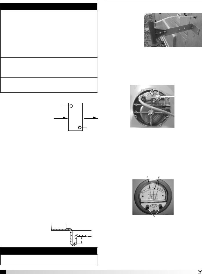
Installation of Building Pressure
Control (optional)
1. Mount Pressure Tap
Using the factory provided bracket, mount the pressure tap to the
outside of the unit. Choose a location out of the prevailing winds and away from supply or exhaust fans to assure accurate readings.
2. Run Pressure Tap Lines
Run a pressure tap line from the pressure tap on the outside of the unit to the low pressure tap on the back of the photohelic gauge. Run a second pressure tap line from the high pressure tap on the back of the photohelic gauge to the space. Fifty feet of tubing is supplied with the unit.
Factory |
|
|
|
High Pressure |
||
|
|
|
||||
|
|
|
Tap |
|||
Wiring |
|
|
|
|
|
to Space |
Low Pressure |
|
|
|
|
||
Tap |
|
|
|
|
|
|
|
|
|
|
|
||
to Outside |
|
|
|
|
||
Connections for Photohelic Gauge
3. Set the Building Pressure
The pressure gauge is used to set the desired building pressure. The pressure is set by adjusting the knobs for the upper and lower pressure limits. Typical settings are 0.0 inch wc for the lower and 0.10 inch wc for the upper pressure setting.
Pressure Indicating |
Pressure Setting |
Needle |
Needles |
Pressure Setting Knobs
Typical Photohelic Gauge Settings
®
Start-Up - Blower
Refer to the Start-Up Checklist in the Reference Section Before Proceeding Further!
Pre Start-Up Check
Rotate the fan wheel by hand and make sure no parts are rubbing. Check the V-belt drive for proper alignment and tension (a guide for proper belt tension and alignment is provided in the Belt Maintenance section). Check fasteners, set screws, and locking collars on the fan, bearings, drive, motor base, and accessories for tightness.
warning
Disconnect and lock-out all power and gas before performing any maintenance or service to the unit. Failure to due so could result in serious injury or death and damage to equipment.
SPECIAL EQUIPMENT REQUIRED
Required and recommended tools. Equivalent products may be used.
Voltage & |
Manufacturer: |
Fluke |
|
Model: |
177 |
||
Amperage |
|||
Phone: |
1-800-44-FLUKE |
||
Meter |
|||
www.fluke.com |
|
||
|
|
||
|
|
|
|
|
Manufacturer: |
Fluke |
|
Thermometer |
Model: |
50 |
|
Phone: |
1-800-44-FLUKE |
||
|
|||
|
www.fluke.com |
|
|
Micro Amp |
Manufacturer: |
Fluke |
|
Model: |
116 |
||
Meter |
Phone: |
1-800-44-FLUKE |
|
|
www.fluke.com |
|
|
U-Tube |
Manufacturer: |
Dwyer |
|
Model: |
Slack Tube |
||
Manometer |
Phone: |
1-219-897-8000 |
|
|
www.dwyer-inst.com |
||
|
Manufacturer: Monarch |
||
Tachometer |
Model: |
Pocket Tach 100 |
|
Phone: |
1-800-999-3390 |
||
|
|||
|
www.monarchinstrument.com |
||
Warning
Check the housing, blower, and ductwork for any foreign objects before running the blower.
1. Check the Voltage
Before starting the unit, compare the supplied voltage, hertz, and phase with the unit and motor’s nameplate
information.
Voltage, Hertz, Phase
VOLTS |
HZ |
PH |
SUP HP
MCA |
MOP |
Unit’s Total MCA
Electrical Nameplate
2. Check the Blower Rotation
Open the blower access door and run the blower momentarily to determine the rotation. Arrows are placed on the blower scroll to
indicate the proper direction or reference the example shown to the right.
|
|
|
n |
|
|
|
io |
|
|
|
t |
|
|
a |
|
R |
o |
t |
|
|
|
||
|
|
|
|
Blower
Housing
Blower Rotation
Note
To reverse the rotation on three phase units, disconnect and lock-out the power, then interchange any two power leads.
Note
To reverse the rotation on single phase units, disconnect and lock-out the power, then rewire the motor per the manufacturer’s instructions.
Important
If the blower is rotating in the wrong direction, the unit will move some air, but will not perform as designed. Be sure to perform a visual inspection to guarantee the correct blower rotation.
3. Check for Vibration
Check for unusual noise, vibration or overheating of the bearings. Reference the Troubleshooting section for corrective actions.
Important
Excessive vibration may be experienced during the initial start-up. Left unchecked, it can cause a multitude of problems including structural and/or component failure.
Important
Generally, fan vibration and noise is transmitted to other parts of the building by the ductwork. To minimize this undesirable effect, the use of heavy canvas duct connectors is recommended.
4. Motor Check
Measure the motor’s voltage, amps and RPM. Compare to the specifications. Motor amps can be reduced by lowering the motor RPM or increasing system static pressure.
Important
Additional starters and overloads may be provided in the make-up air control center for optional exhaust blowers. Any additional overloads must be checked for proper voltage, amps and RPMs.
5. Air Volume Measurement & Check
Measure the unit’s air volume (CFM) and compare it with its rated air volume. If the measured air volume is off, adjust the fan’s RPM by changing/adjusting the drive.
Model IG / IGX Make-Up Air 23
®
 Loading...