


ZDP304LP2SS
GE ZDP304LP2SS, ZDP304LP3SS, ZDP304LP4SS, ZDP304LP5SS, ZDP304LP6SS Installation Guide
...
Installation
Instructions
30", 36" and 48"
Professional Ranges
Cuisini_res professionnelles
de 30" (76 cm), 36" (91 cm)
et de 48" (121 cm)
Instructions d'installation
La section fran_aise commence 6 la page 24
131-i0689-31
06-09JR
Cocinas profesionales
de 30", 36"y 48"
Instrucciones de instalaci6n
La secci6n en espa6ol empieza en la p6gina 46
Installation Instructions
BEFORE YOU BEGIN
Readthese instructions completely and carefully.
• IMPORTANT-Savethese instructionsfor local
inspector's use.
• IMPORTANT-Observeallgoverningcodesand
ordinances.
• Note to Installer- Besureto leavethese instructions
with the Consumer.
° Note to Consumer- Keepthese instructions
with your Owner's Manualfor future reference.
• Completion Time- i to 3 hours.
• Properinstallation isthe responsibility ofthe installer.
Productfailure due to improper installation isnot covered
under the warranty. SeeOwner's Manualfor warranty
information.
- WARNING:
Thisappliance must be properly grounded. See"Electric
Supply."
ForMonogram localservice in your area,1.800.444.1845.
ForMonogram Servicein Canada,call 1.800.561.3344.
ForMonogram Partsand Accessories,call 1.800.626.2002.
If you receiveda damaged range,you should contact your
dealer.
Inthe Commonwealth of Massachusetts:
• Thisproduct must be installed by a licensedplumber or gas
fitter.
• When usingballtype gas shut off valves,they shall be
T-handletype.
• A flexible gasconnector,when used,must not exceed
3feet.
-AWARNING:
All ranges can tip. Injury could result. Install the
supplied Anti-Tip Bracket provided. See instructions
in this manual or with the bracket.
Ifsoldoutside the U.S.and Canada:
Vent hood Combinations:
It isrecommended that these ranges be installed
in conjunction with a suitable overhead vent hood.
• Installahood with at least 1200CFMabove a 48"
wide range.
• Installahood with at least600 CFMabove a 30"
or 36" range.
Dueto the high heat capacity ofthis unit, particular attention
should be paid to the hood and ductwork installation to
assure it meets local building codes.
-AWARNING:
Clearancesto horizontal surfaces above the range,
measured to the cooking surface:
• Installationswithout a hood require 48"minimum
to combustibles.
• A custom hood installation with exposedhorizontal
combustiblessurfaces must have an Auto-On feature.
• Forother installationswith a hood,refer to hood installation
instructionsfor specifichood clearances.
- CAUTION:
Theserangesweigh up to 700 pounds. Somedisassembly
will reduce the weight considerably. Dueto the weight and
sizeof the range and to reducethe riskof personal injury
or damage to the product:
TWOPEOPLEAREREQUIREDFORPROPERINSTALLATION
OF36" AND 30" RANGES.
THREEPEOPLEAREREQUIREDFORPROPERINSTALLATION
OF48" RANGES.
Leaktesting of the appliance shallbe conducted according
to the manufacturer's instructions.
Installation must conform with localcodes. Inthe absence
of local codes,the range must comply with the National Fuel
GasCode,ANSIZ223.1/NFPA54,latest edition and National
ElectricalCode ANSI/NFPA70 latest addition. In Canada,
installation must conform with the current Natural Gas
Installation Code,CAN/CGA-B149.1or the current Propane
Installation Code,CAN/CGA-B149.2,and with local codes
where applicable.Thisrange hasbeen design-certified by
CSAInternational according to ANSIZ21.1,latest edition and
CanadianGas Associationaccording to CAN/CGA-I.1latest
edition.
-AWARNING:lfyouwishtousethis product with
Liquefied Petroleum (LP)gas containing greater than 10%
butane, you must purchase the butane conversion kit
#WB28K10589. Toorder, please call 1.888.664.8403
or 1.787.276.4051.
Design Information
CONTENTS
Design Information
Models Available ......................................................................3
Backsplash Accessories ......................................................3
Product Dimensions and Clearances ......................../4-7
Tools and Materials Required ..........................................8
Installation Preparation
Power Supplg Locations ..............................................9, 10
MODELS AVAILABLE
These Monogram ranges are factorg set for either
natural gas or LP gas. Order the model for gour
installation situation.
48" Natural Gas Models:
ZDP484NG - 4 gas burners, grill and griddle
ZDP486NR - 6 gas burners and grill
ZDP486ND - 6 gas burners and griddle
48" LP Gas Models:
ZDP484LG - 4 gas burners, grill and griddle
ZDP486LR - 6 gas burners and grill
ZDP486LD - 6 gas burners and griddle
Installation Instructions
Step 1, Remove Packaging ..............................................
Step 2, Move Range Indoors ..........................................
Step 3, Install Anti-Tip Device ........................................
Step 4, Connect Range to Gas........................................
Step 5, Connect Electrical ................................................
Step 6, Roll Range into Position ....................................
Step 7, Level the Range ....................................................
Step 8, Replace Oven Doors ............................................
Step 9, Check Burners ........................................................
Finalize Installation ..............................................................
Installation Checklist ..........................................................
Accessories ..............................................................................
1
2
3
.4
4
4
5
5
6
6
6
7
Accessorg Installation ................................................18J20
Gas Conversion ............................................................21-23
36" Natural Gas Models:
ZDP366N - 6 gas burners
ZDP364NR- 4 gas burners and grill
ZDP364ND - 4 gas burners and griddle
36" LP Gas Models:
ZDP366L - 6 gas burners
ZDP364LR - 4 gas burners and grill
ZDP364LD - 4 gas burners and griddle
30" Natural Gas Model: ZDP304N
30" LP Gas Model: ZDP304L
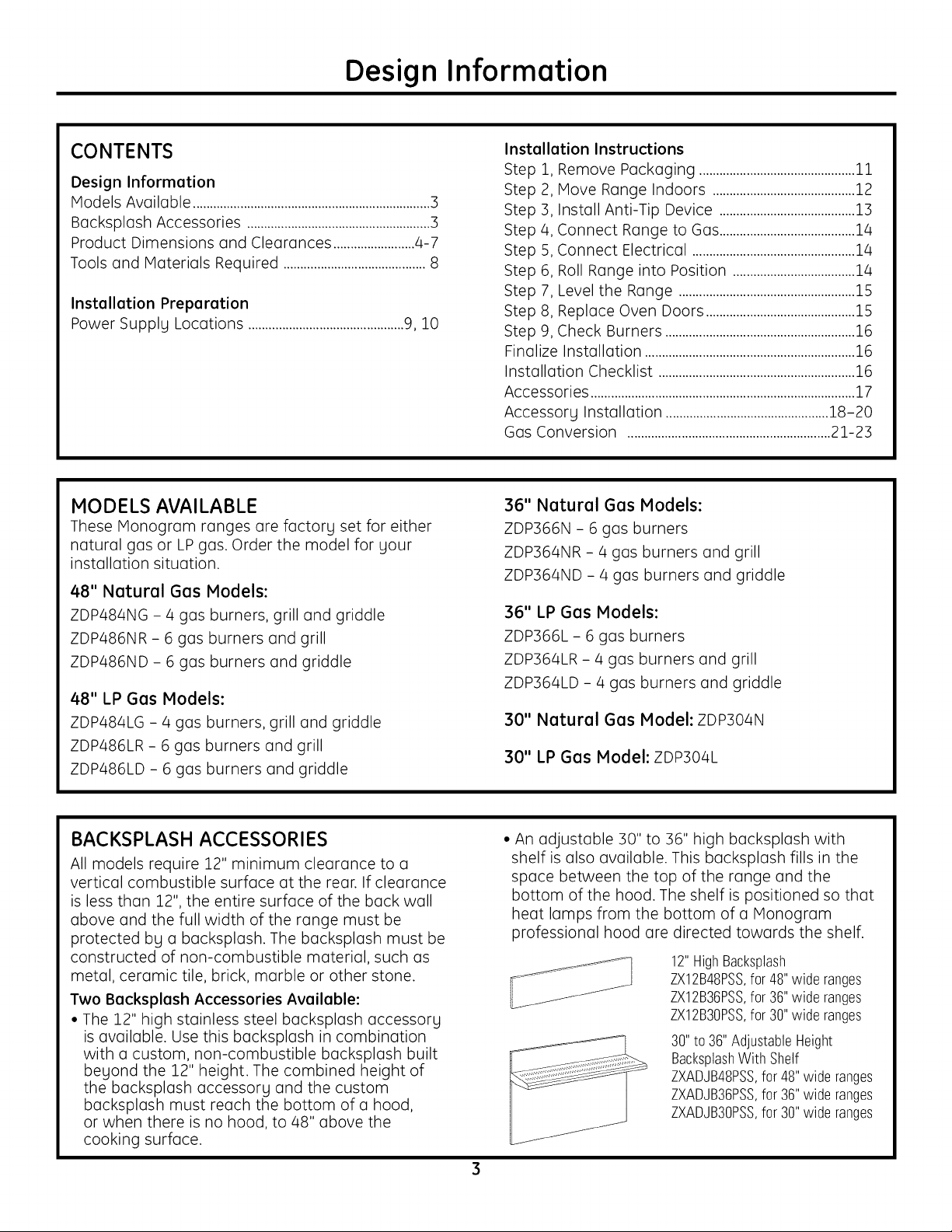
BACKSPLASH ACCESSORIES
All models require 12" minimum clearance to a
vertical combustible surface at the rear. If clearance
is less than 12L the entire surface of the back wall
above and the full width of the range must be
protected by a backsplash. The backsplash must be
constructed of non-combustible material, such as
metal, ceramic tile, brick, marble or other stone.
Two Backsplash Accessories Available:
• The 12" high stainless steel backsplash accessorg
is available. Use this backsplash in combination
with a custom, non-combustible backsplash built
begond the 12" height. The combined height of
the backsplash accessorg and the custom
backsplash must reach the bottom of a hood,
or when there is no hood, to 48" above the
cooking surface.
• An adjustable 30" to 36" high backsplash with
shelf is also available. This backsplash fills in the
space between the top of the range and the
bottom of the hood. The shelf is positioned so that
heat lamps from the bottom of a Monogram
professional hood are directed towards the shelf.
12"HighBacksplash
ZX12B48PSS,for48"wideranges
ZX12B36PSS,for36"wideranges
ZX12B30PSS,for30"wideranges
30"to36" AdjustableHeight
BacksplashWith Shelf
ZXADJB48PSS,for 48"wide ranges
ZXADJB36PSS,for 36"wide ranges
ZXADJB30PSS,for 30"wide ranges
Design Information
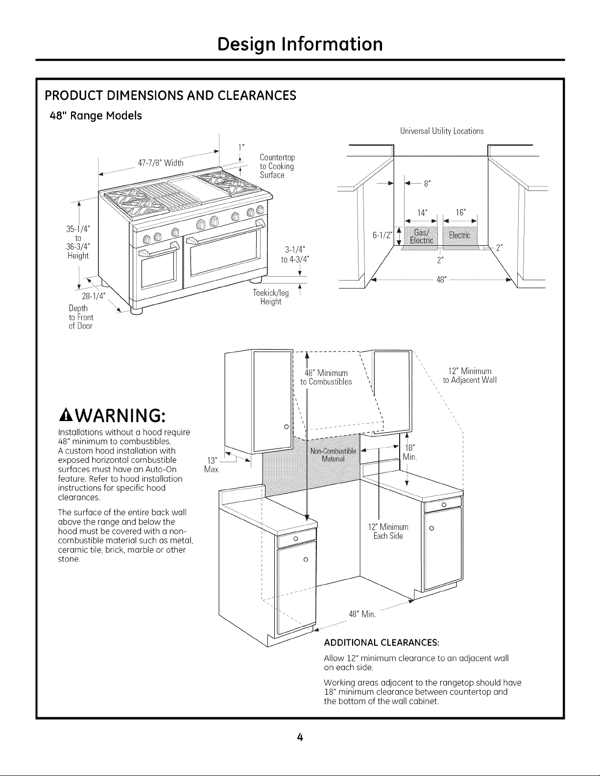
PRODUCT DIMENSIONS AND CLEARANCES
48" Range Models
1 "
Countertop
_ .......47-7/8"Width to Cooking
.............. Surface
UniversalUtilityLocations
35-1/4"
to
36-3/4"
Height
28-1/4"
Depth
to Front
of Door
WARNING:
Installations without a hood require
48" minimum to combustibles.
Acustom hood installation with
exposed horizontal combustible
surfaces must have an Auto-On
feature. Refer to hood installation
instructions for specific hood
clearances.
The surface of the entire back wall
above the range and below the
hood must be covered with a non-
combustible material such as metal,
ceramic tile, brick, marble or other
stone.
Ii i
3-1/4"
to 4-3/4"
Toekick/leg _'
Height
12"Minimum
', toAdacentWall
Max.
ADDITIONAL CLEARANCES:
Allow 12" minimum clearance to an adjacent wall
on each side.
Working areas adjacent to the rangetop should have
18" minimum clearance between countertop and
the bottom of the wall cabinet.
4

Design Information
PRODUCT DIMENSIONS AND CLEARANCES
36" Range Models
1 "
35-7/8"Width
35-1/4"
to
36-3/4"
Height
Countertop
to Cooking
Surface
UniversalUtility Locations
28-1/4"
Depth
to Front
of Door
-AWARNING:
Instollotions without o hood require
48" minimum to combustibles.
A custom hood instollotion with
exposed horizontol combustible
surfoces must hove on Auto-On
feoture. Refer to hood instollotion
instructions for specific hood
cleoronces.
The surfoce of the entire bock woll
obove the ronge ond below the
hood must be covered with o non-
combustible moteriol such os metol,
ceromic tile, brick, morble or other
stone.
Toekick/leg
Height
12"Minimum
to Ac acentWall
48"Minimum
toCombustibles
Max.
ADDITIONAL CLEARANCES:
Allow 12" minimum cleoronce to on odjocent woll
on each side.
Working oreos odjocent to the rongetop should hove
18" minimum cleoronce between countertop ond
the bottom of the woll cobinet.
5
Design Information
PRODUCT DIMENSIONS AND CLEARANCES
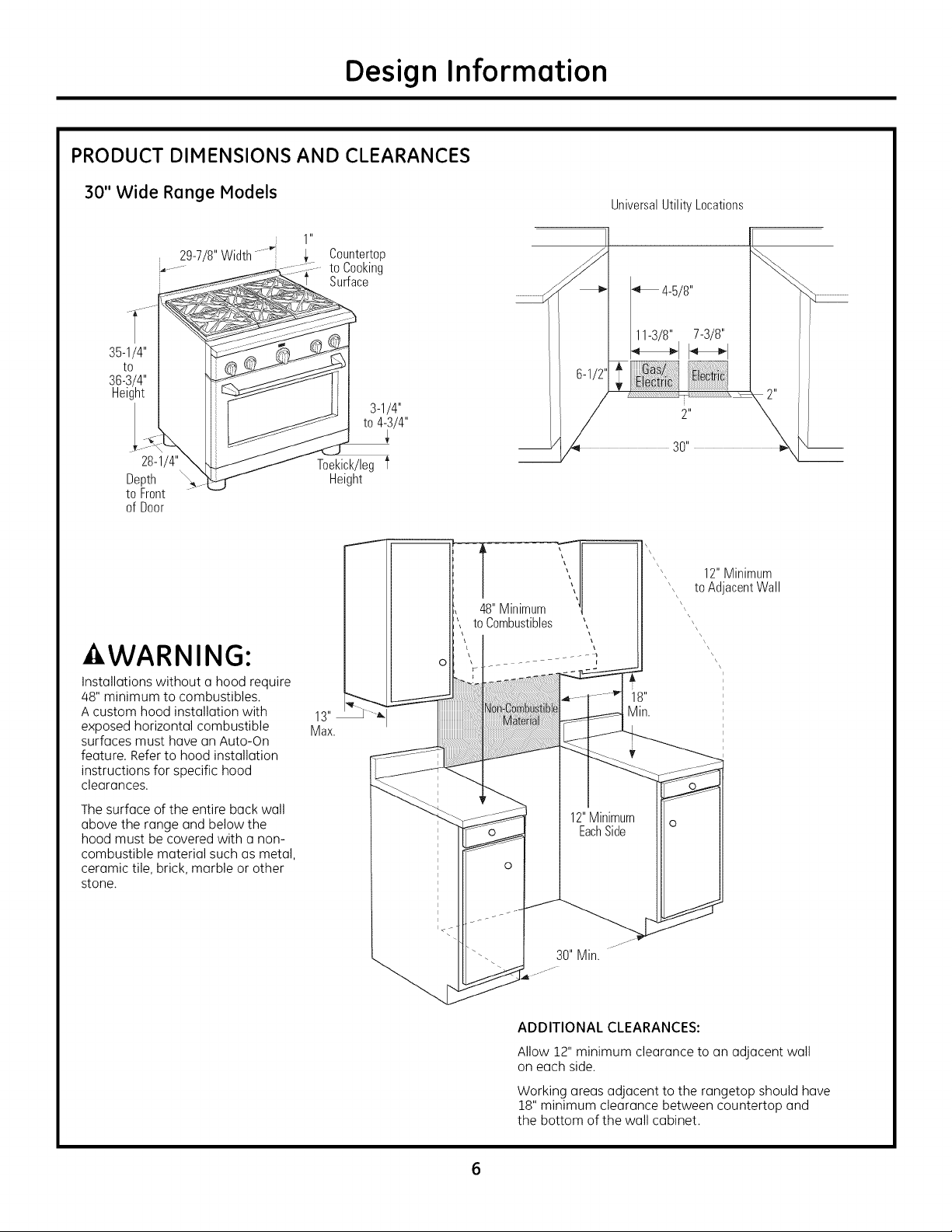
30" Wide Range Models
29-7/8"Width
35-1/4"
to
36-3/4"
Height
28-1/4"
Depth
to Front
of Door
1 "
Countertop
to Cooking
Surface
Toekick/leg f
Height
UniversalUtility Locations
12"Minimum
\\
\\
to Ac acentWall
WARNING:
Installations without a hood require
48" minimum to combustibles.
Acustom hood installation with
exposed horizontal combustible
surfaces must have an Auto-On
feature. Refer to hood installation
instructions for specific hood
clearances.
The surface of the entire back wall
above the range and below the
hood must be covered with a non-
combustible material such us metal,
ceramic tile, brick, marble or other
stone.
ADDITIONAL CLEARANCES:
Allow 12" minimum clearance to an adjacent wall
on each side.
Working areas adjacent to the rangetop should have
18" minimum clearance between countertop and
the bottom of the wall cabinet.
Design Information
PRODUCT DIMENSIONS AND CLEARANCES
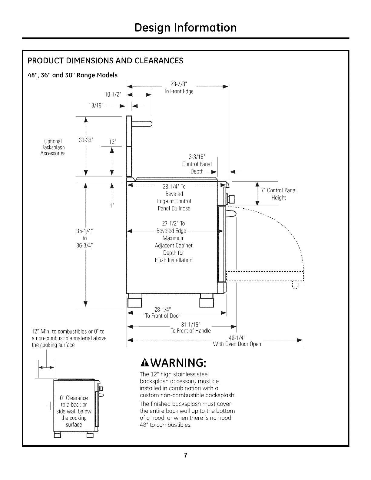
48", 36" and 30" Range Models
28-7/8" ............................................................
10-1/2" _
13/16" I_ 4
A
ToFrontEdge
Optional
Backsplash
Accessories
30-36"
35-1/4"
to
36-3/4"
v
,,
A
--__
,,11 28-1/4"To
,1
,4t
bl b1
4 ToFrontof Door
3-3/16"
ControlPanel
Beveled
Edgeof Control
PanelBullnose
27-1/2"To
BeveledEdge
Maximum
AdjacentCabinet
Depthfor
FlushInstallation
28-1/4"
Depth
4
A
7" ControlPanel
Height
V
u
u
u
12"Min.to combustiblesor0"to
a non-combustiblematerialabove
thecookingsurface
0"Clearance
- toabackor
sidewall below
thecooking
surface
4 31-1/16"
ToFrontof Handle
48-1/4" 11_
With OvenDoorOpen
- WARNING:
The 12" high stoinless steel
bocksplosh occessorg must be
instolled in combinotion with o
custom non-combustible backsplash.
The finished backspl(]sh must cover
the entire back wall up to the bottom
of a hood, or when there is no hood,
48" to combustibles.
Installation Information
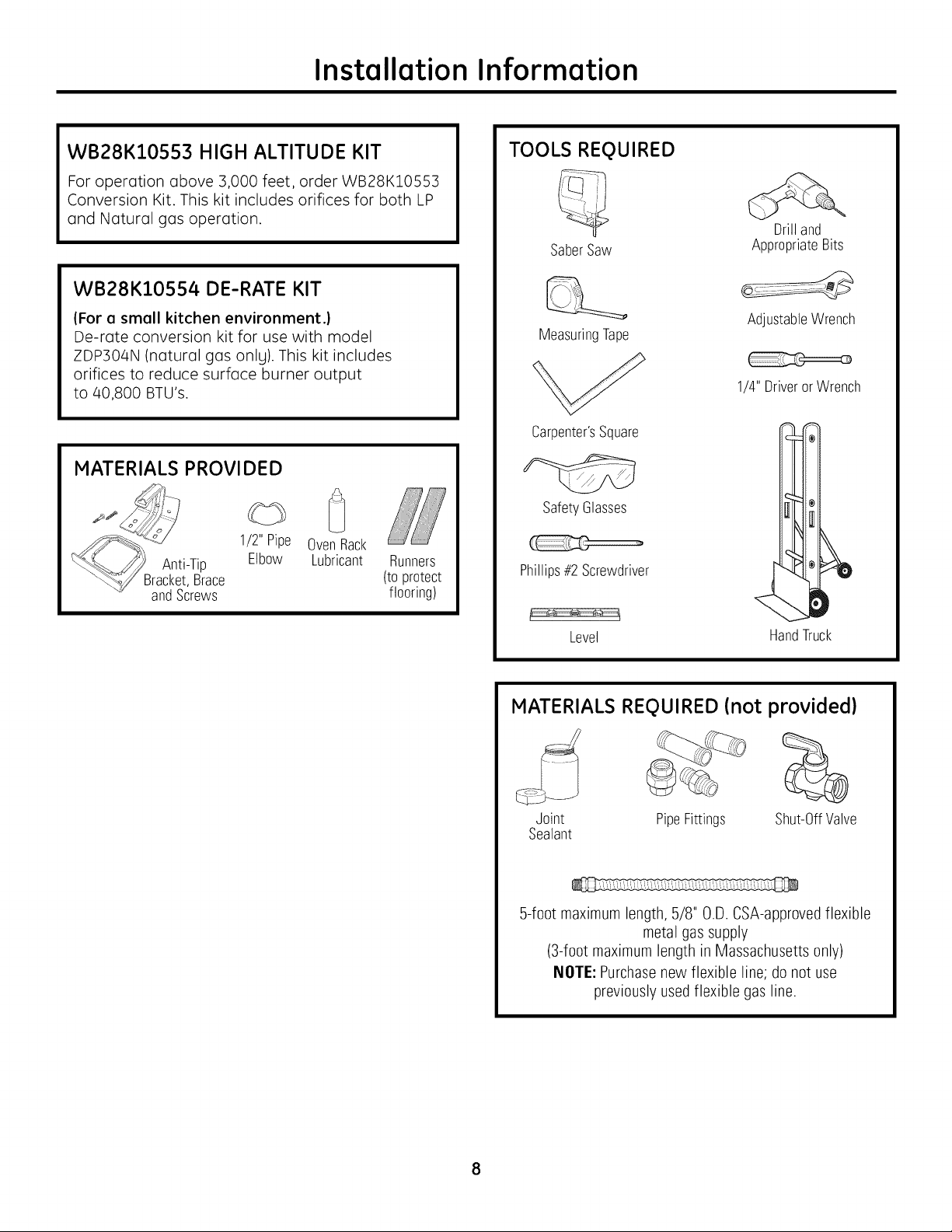
WB28K10553 HIGH ALTITUDE KIT
For operation above :3,000 feet, order WB28K10553
Conversion Kit. This kit includes orifices for both LP
and Natural gas operation.
WB28K10554 DE-RATE KIT
(For e smell kitchen environment.)
De-rate conversion kit for use with model
ZDP304N (natural gas only). This kit includes
orifices to reduce surface burner output
to 40,800 BTU's.
MATERIALS PROVIDED
1/2" Pipe
Anti-Tip Elbow
3racket,Brace
andScrews
OvenRack
Lubricant
Runners
(toprotect
flooring)
TOOLS REQUIRED
SaberSaw
MeasuringTape
Carpenter'sSquare
SafetyGlasses
Phillips#2Screwdriver
Drilland
AppropriateBits
AdjustableWrench
1/4" DriverorWrench
Level
HandTruck
MATERIALS REQUIRED (not provided)
Joint PipeFittings Shut-OffValve
Sealant
5-foot maximum length, 5/8" 0.D. CSA-approvedflexible
metal gas supply
(3-foot maximum length in Massachusetts only)
NOTE: Purchasenew flexible line; do not use
previously used flexible gas line.
POWER SUPPLY LOCATIONS
Installation Preparation
Gas Supplg:
•The naturalgas models are designed tooperate
at 5"water column pressure.Forproper operation,
the pressureofthe naturalgas suppliedtothe
regulatormust be between 7"and 13"water
column.
• The LP models are designed to operate at 10"
water column pressure. For proper operation,
the pressure of the LP gas supplied to
the regulator must be between 11"
and 13" water column.
• A 1/2" elbow is provided for connection
to the range gas inlet, located at the rear
and near the floor.
• Locate the pipe stub on the back wall or floor
as illustrated in "Dimensions and Clearances."
Use S-foot maximum length, 5/8" O.D. flexible
gas supplg line (3-foot in Massachusetts).
• Install o manual shut-off valve in the gas line
(not provided), in on eosilg accessible location.
Make sure the homeowner knows where
and how to shut off the gas supplg to the range.
Electric Supplg:
These ranges must be supplied with 208/240 volt,
60 Hz., and connected to an individual, properlg
grounded branch circuit protected bg a circuit
breaker or time delog fuse (50 amp for 48" ranges,
30 amp for 36" and 30" ranges). The receptacle
must be o NEMA 14-50R device to accept the
4-prong plug supplied with the range.
If the electrical service provided does not meet
the above specifications, it is recommended that
a licensed electrician install an approved outlet.
• Locate the electric supply as illustrated
in "Dimensions and Clearances."
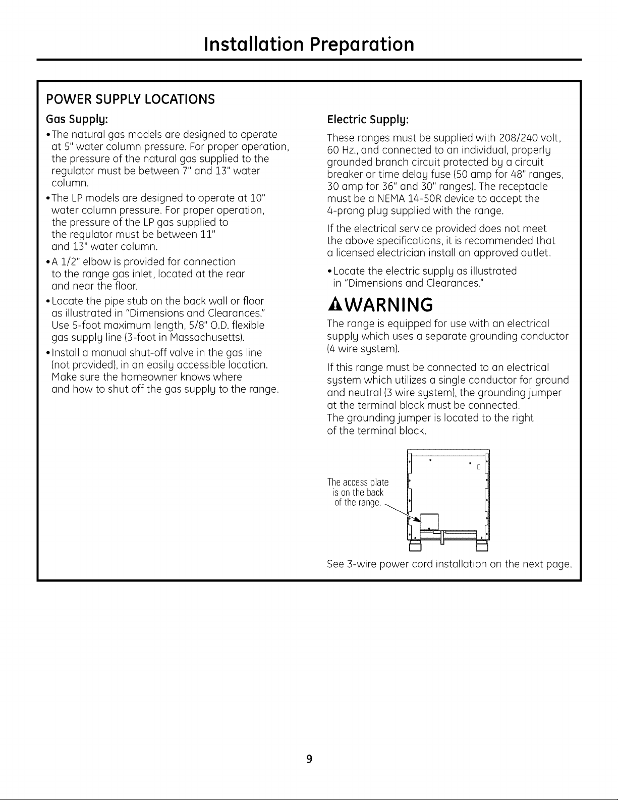
WARNING
The range is equipped for use with an electrical
supply which uses a separate grounding conductor
(4 wire system).
If this range must be connected to an electrical
system which utilizes a single conductor for ground
and neutral (3 wire system), the grounding jumper
at the terminal block must be connected.
The grounding jumper is located to the right
of the terminal block.
o
Theaccessplate
is onthe back
of the range.
See 3-wire power cord installation on the next page.
o
D
Installation Preparation
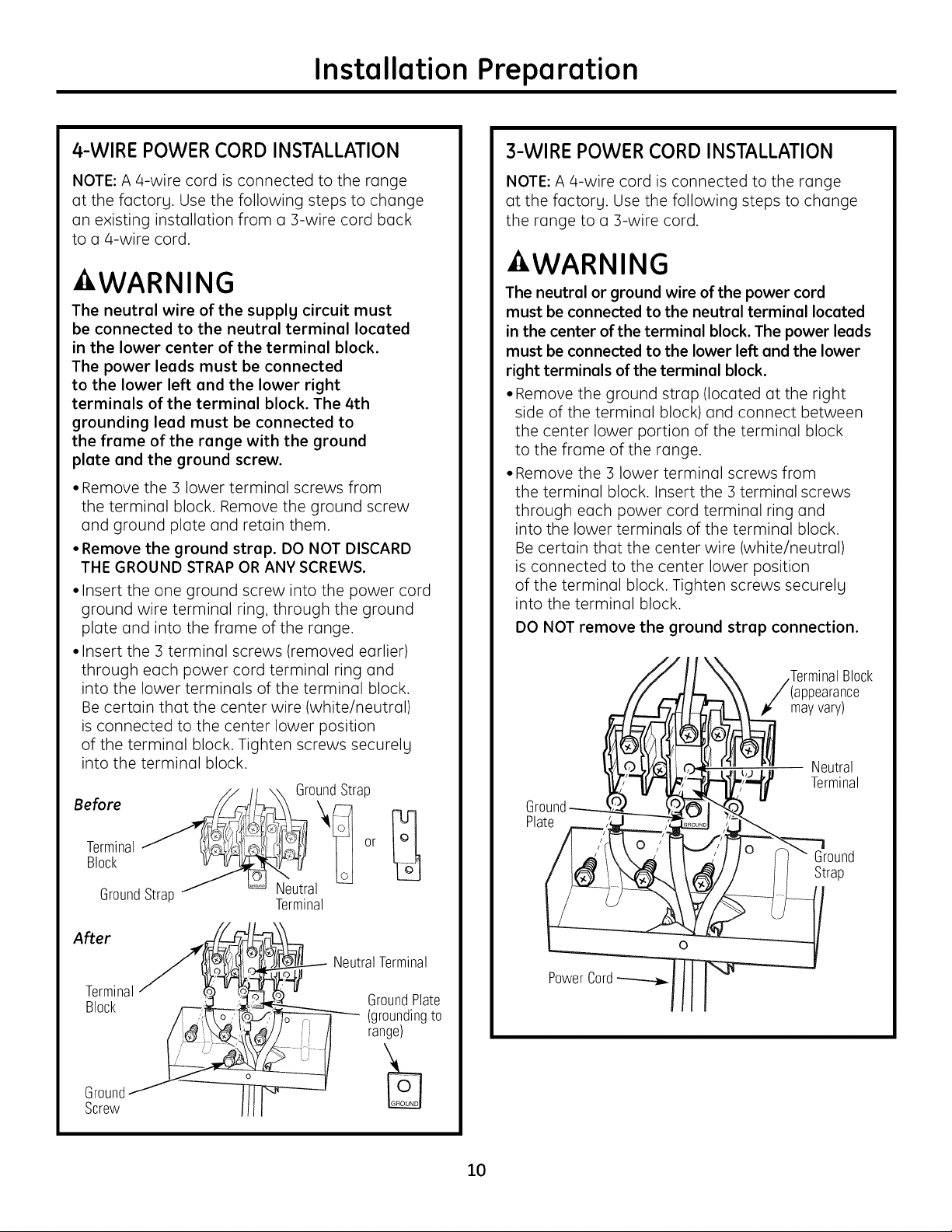
4-WIRE POWER CORD INSTALLATION
NOTE: A a-wire cord is connected to the range
at the factory. Use the following steps to change
an existing installation from a 3-wire cord back
to a a-wire cord.
-&WARNING
The neutral wire of the supplg circuit must
be connected to the neutral terminal located
in the lower center of the terminal block.
The power leeds must be connected
to the lower left end the lower right
terminals of the terminal block. The 4th
grounding lead must be connected to
the frame of the range with the ground
plate end the ground screw.
• Remove the 3 lower terminal screws from
the terminal block. Remove the ground screw
and ground plate and retain them.
• Remove the ground strap. DO NOT DISCARD
THE GROUND STRAP OR ANY SCREWS.
• Insert the one ground screw into the power cord
ground wire terminal ring, through the ground
plate and into the frame of the range.
• Insert the 3 terminal screws (removed earlier)
through each power cord terminal ring and
into the lower terminals of the terminal block.
Be certain that the center wire (white/neutral)
is connected to the center lower position
of the terminal block. Tighten screws securely
into the terminal block.
GroundStrap
3-WIRE POWER CORD INSTALLATION
NOTE: A 4-wire cord is connected to the range
atthe factory. Use the following steps to change
the range to a 3-wire cord.
-AWARNING
The neutral or ground wire of the power cord
must be connected to the neutral terminal located
in the center of the terminal block. The power leeds
must be connected to the lower left end the lower
right terminals of the terminal block.
• Remove the ground strap (located at the right
side of the terminal block) and connect between
the center lower portion of the terminal block
to the frame of the range.
• Remove the 3 lower terminal screws from
the terminal block. Insert the 3 terminal screws
through each power cord terminal ring and
into the lower terminals of the terminal block.
Be certain that the center wire (white/neutral)
is connected to the center lower position
of the terminal block. Tighten screws securely
into the terminal block.
DO NOT remove the ground strap connection.
.TerminalBlock
3earance
mayvary)
Neutral
Terminal
Terminal or
Block
GroundStrap Neutral
After
Terminal
Block
Ground
Screw
Terminal
NeutralTerminal
Plate
Ground
Strap
PowerCord
GroundPlate
(groundingto
range)
10
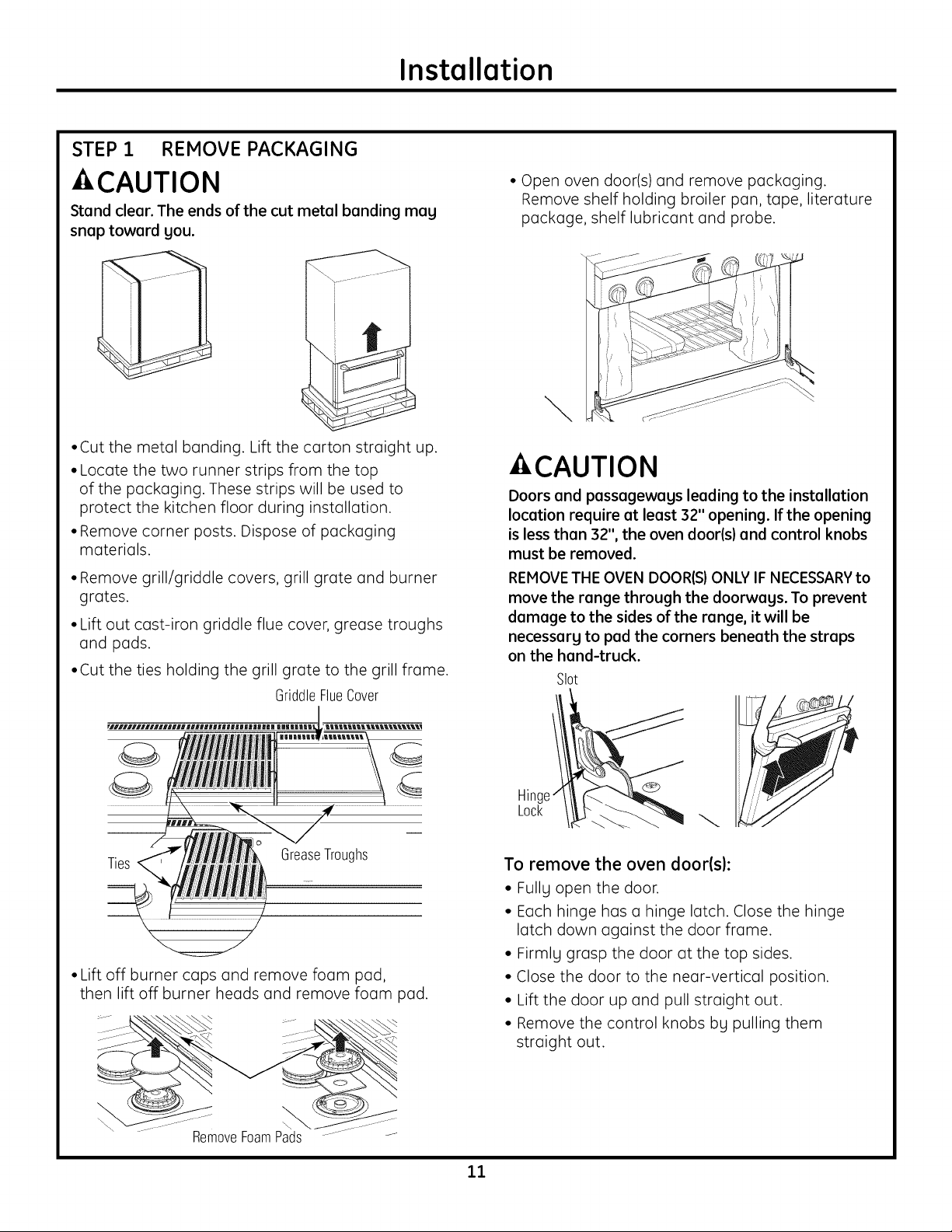
STEP 1 REMOVE PACKAGING
Installation
- CAUTION
Stand clear. The ends of the cut metal banding mag
snap toward gou.
•Cut the metal banding. Lift the carton straight up.
• Locate the two runner strips from the top
of the packaging. These strips will be used to
protect the kitchen floor during installation.
• Remove corner posts. Dispose of packaging
materials.
• Remove grill/griddle covers, grill grate and burner
grates.
• Lift out cast-iron griddle flue cover, grease troughs
and pads.
•Cut the ties holding the grill grate to the grill frame.
GriddleFlueCover
• Open oven door(s) and remove packaging.
Remove shelf holding broiler pan, tape, literature
package, shelf lubricant and probe.
\
CAUTION
Doors and passagewags leading to the installation
location require at least 32" opening. If the opening
is less than 32", the oven door(s) and control knobs
must be removed.
REMOVETHE OVEN DOOR(S)ONLY IF NECESSARYto
move the range through the doorwags. To prevent
damage to the sides of the range, it will be
necessarg to pad the corners beneath the straps
on the hand-truck.
G
Ties
• Lift off burner caps and remove foam pad,
then lift off burner heads and remove foam pad.
RemoveFoamPads
GreaseTroughs
Hinge
Lock
To remove the oven door(s):
• Fully open the door.
• Each hinge has a hinge latch. Close the hinge
latch down against the door frame.
• Firmlg grasp the door at the top sides.
• Close the door to the near-vertical position.
• Lift the door up and pull straight out.
• Remove the control knobs bg pulling them
straight out.
11
Installation Preparation
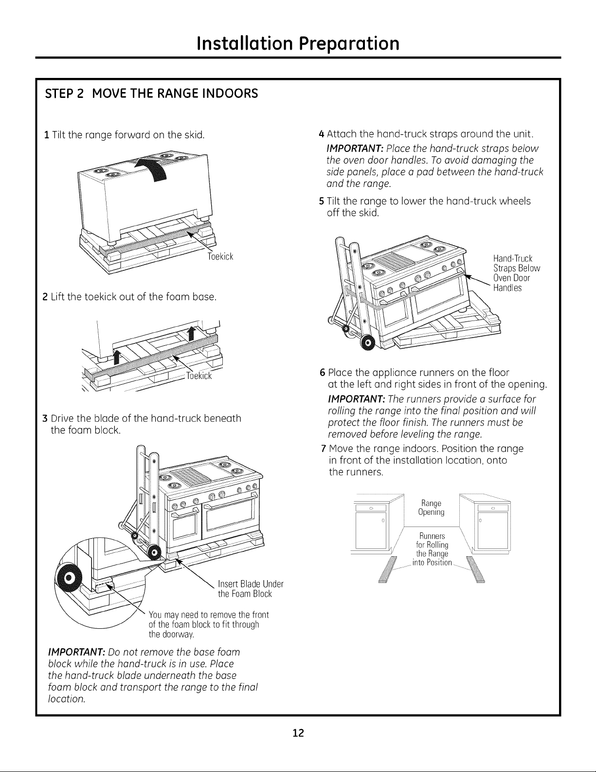
STEP 2 MOVE THE RANGE INDOORS
1 Tilt the range forward on the skid.
_Toekick
2 Lift the toekick out of the foam base.
, ,,J
,_,_" _i_I
3 Drive the blade of the hand-truck beneath
the foam block.
4 Attach the hand-truck straps around the unit.
IMPORTANT: Place the hand-truck strops below
the oven door handles. To ovoid damaging the
side ponds, place a pod between the hand-truck
and the range.
5 Tilt the range to lower the hand-truck wheels
off the skid.
Hand-Truck
StrapsBelow
OvenDoor
Handles
6 Place the appliance runners on the floor
at the left and right sides in front of the opening.
IMPORTANT: The runners provide a surface for
rolling the range into the final position and will
protect the floor finish. The runners must be
removed before leveling the range.
7 Hove the range indoors. Position the range
in front of the installation location, onto
the runners.
InsertBladeUnder
the FoamBlock
Youmayneedto removethefront
ofthe foamblockto fit through
the doorway.
IMPORTANT: Do not remove the base foam
block while the hand-truck is in use. Place
the hand-truck blade underneath the bose
foam block and transport the range to the final
location.
Range
Opening
Runners
forRolling
the Range
Position
12
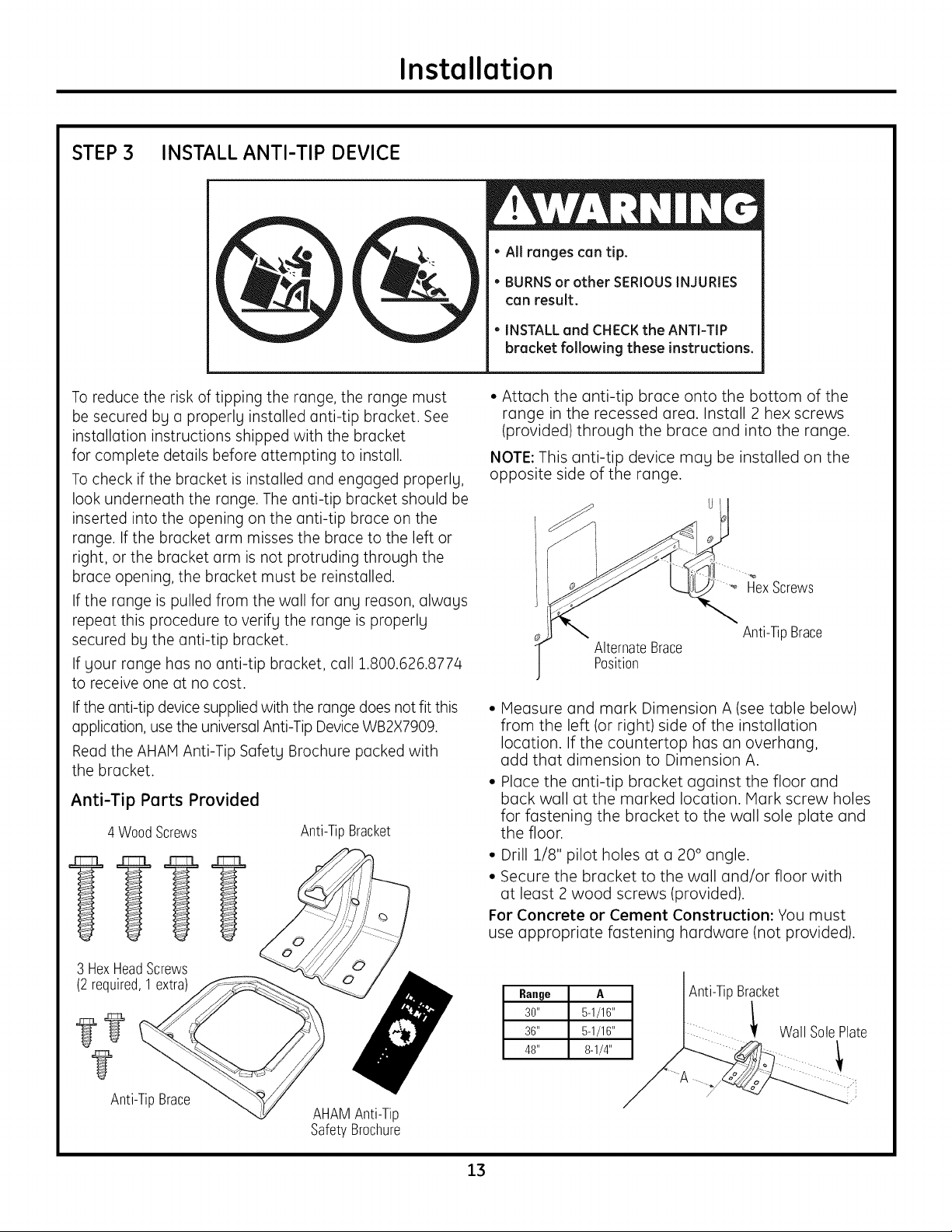
STEP 3 INSTALL ANTI-TIP DEVICE
Installation
• All ranges can tip.
• BURNSor other SERIOUSINJURIES
can result.
INSTALL and CHECK the ANTI-TIP
bracket following these instructions.
To reduce the risk of tipping the range, the range must
be secured by a properly installed anti-tip bracket. See
installation instructions shipped with the bracket
for complete details before attempting to install.
To check if the bracket is installed and engaged properly,
look underneath the range. The anti-tip bracket should be
inserted into the opening on the anti-tip brace on the
range. If the bracket arm misses the brace to the left or
right, or the bracket arm is not protruding through the
brace opening, the bracket must be reinstalled.
If the range is pulled from the wall for any reason, always
repeat this procedure to verify the range is properly
secured by the anti-tip bracket.
If your range has no anti-tip bracket, call 1.800.626.8774
to receive one at no cost.
Ifthe anti-tip device supplied with the range does not fit this
application, use the universal Anti-Tip Device WB2X7909.
Read the AHAIVlAnti-Tip Safety Brochure packed with
the bracket.
Anti-Tip Parts Provided
4 WoodScrews
Anti-TipBracket
• Attach the anti-tip brace onto the bottom of the
range in the recessed area. Install 2 hex screws
(provided) through the brace and into the range.
NOTE: This anti-tip device mag be installed on the
opposite side of the range.
HexScrews
Anti-TipBrace
AlternateBrace
Position
• Measure and mark Dimension A (see table below)
from the left (or right) side of the installation
location. If the countertop has an overhang,
add that dimension to Dimension A.
• Place the anti-tip bracket against the floor and
back wall at the marked location. Mark screw holes
for fastening the bracket to the wall sole plate and
the floor.
• Drill 1/8" pilot holes at a 20 ° angle.
• Secure the bracket to the wall and/or floor with
at least 2 wood screws (provided).
For Concrete or Cement Construction: You must
use appropriate fastening hardware (not provided).
3 HexHeadScrews
(2 required,1extra)
Anti-TipBrace
AHAMAnti-Tip
SafetyBrochure
13
Ra.ge A Anti-TipBracket
30" 5-1/16" !
36" 5-1/16" Wall SolePlate
48" 8-1/4"
/
......!
Installation
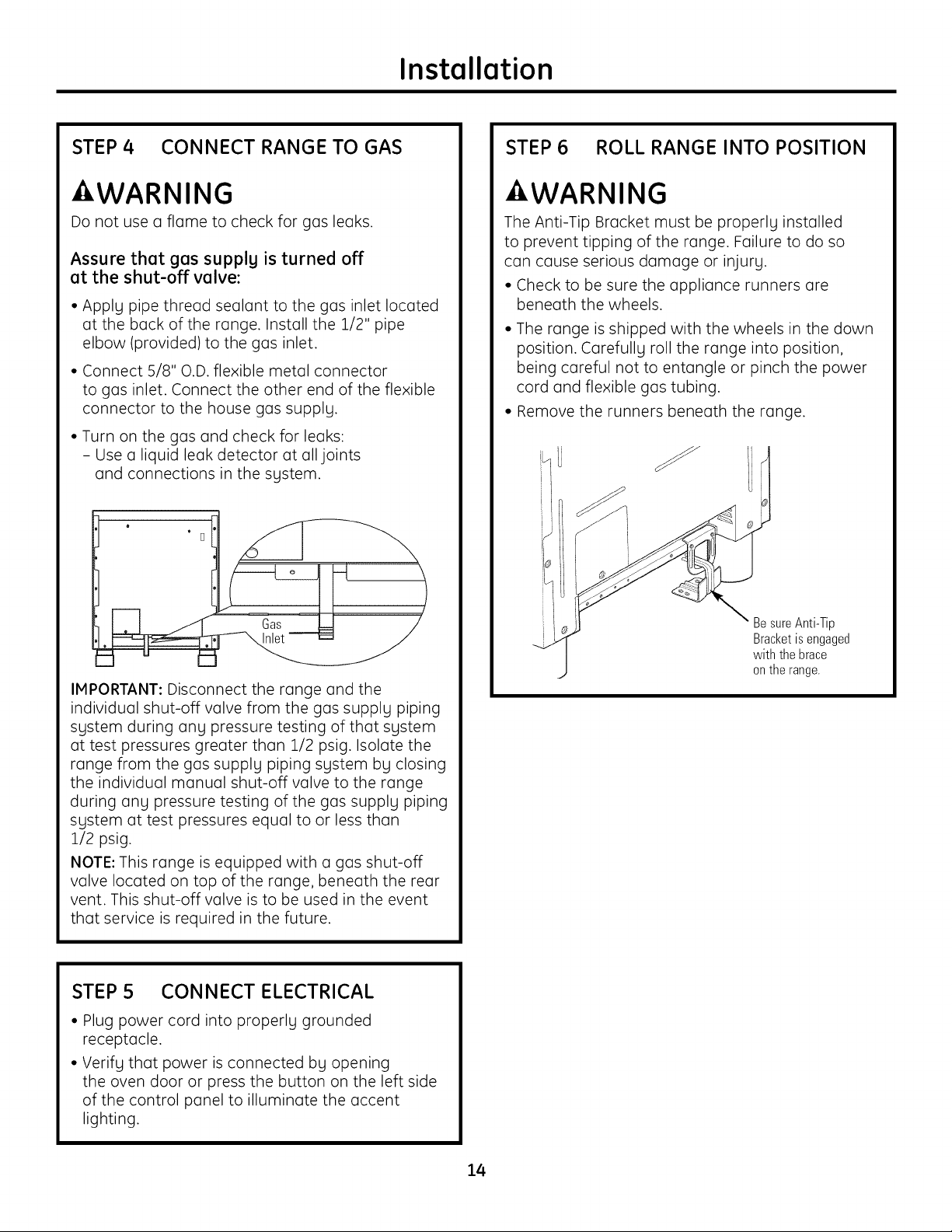
STEP 4 CONNECT RANGE TO GAS
WARNING
Do not use a flame to check for gas leaks.
Assure that gas supplg is turned off
at the shut-off valve:
• Apply pipe thread sealant to the gas inlet located
at the back of the range. Install the 1/2" pipe
elbow (provided) to the gas inlet.
• Connect 5/8" O.D. flexible metal connector
to gas inlet. Connect the other end of the flexible
connector to the house gas supply.
• Turn on the gas and check for leaks:
- Use a liquid leak detector at all joints
and connections in the system.
STEP 6 ROLL RANGE INTO POSITION
AWARNING
The Anti-Tip Bracket must be properly installed
to prevent tipping of the range. Failure to do so
can cause serious damage or injury.
• Check to be sure the appliance runners are
beneath the wheels.
• The range is shipped with the wheels in the down
position. Carefully roll the range into position,
being careful not to entangle or pinch the power
cord and flexible gas tubing.
• Remove the runners beneath the range.
IMPORTANT: Disconnect the range and the
individual shut-off valve from the gas supply piping
system during any pressure testing of that system
at test pressures greater than 1/2 psig. Isolate the
range from the gas supply piping system by closing
the individual manual shut-off valve to the range
during any pressure testing of the gas supply piping
system at test pressures equal to or less than
1/2 psig.
NOTE: This range is equipped with a gas shut-off
valve located on top of the range, beneath the rear
vent. This shut-off valve is to be used in the event
that service is required in the future.
STEP 5 CONNECT ELECTRICAL
• Plug power cord into properly grounded
receptacle.
• Verify that power is connected by opening
the oven door or press the button on the left side
of the control panel to illuminate the accent
lighting.
Be sure Anti-Tip
Bracket is engaged
with the brace
on the range.
14
Installation
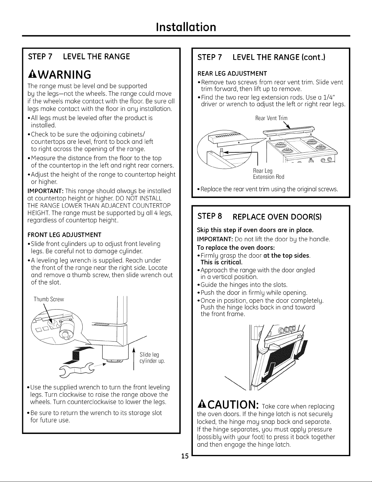
STEP 7 LEVEL THE RANGE
WARNING
The range must be level and be supported
by the legs-not the wheels. The range could move
if the wheels make contact with the floor. Be sure all
legs make contact with the floor in any installation.
• All legs must be leveled after the product is
installed.
• Check to be sure the adjoining cabinets/
countertops are level, front to back and left
to right across the opening of the range.
• Measure the distance from the floor to the top
of the countertop in the left and right rear corners.
• Adjust the height of the range to countertop height
or higher.
IMPORTANT: This range should always be installed
at countertop height or higher. DO NOT INSTALL
THE RANGE LOWERTHAN ADJACENT COUNTERTOP
HEIGHT. The range must be supported by all/4 legs,
regardless of countertop height.
FRONT LEG ADJUSTMENT
• Slide front cylinders up to adjust front leveling
legs. Be careful not to damage cylinder.
• A leveling leg wrench is supplied. Reach under
the front of the range near the right side. Locate
and remove a thumb screw, then slide wrench out
of the slot.
ThumbScrew
STEP 7 LEVEL THE RANGE (cont.}
REAR LEG ADJUSTMENT
• Remove two screws from rear vent trim. Slide vent
trim forward, then lift up to remove.
• Find the two rear leg extension rods. Use a 1/4"
driver or wrench to adjust the left or right rear legs.
RearVent_im
RearLeg
ExtensionRod
• Replace the rear vent trim using the original screws.
STEP 8 REPLACE OVEN DOOR(S}
Skip this step if oven doors ere in place.
IMPORTANT: Do not lift the door by the handle.
To replace the oven doors:
• Firmly grasp the door at the top sides.
This is critical.
• Approach the range with the door angled
in a vertical position.
• Guide the hinges into the slots.
• Push the door in firmly while opening.
• Once in position, open the door completely.
Push the hinge locks back in and toward
the front frame.
Slideleg
cylinderup.
• Use the supplied wrench to turn the front leveling
legs. Turn clockwise to raise the range above the
wheels. Turn counterclockwise to lower the legs.
• Be sure to return the wrench to its storage slot
for future use.
-ACAUTION: Take care when replacing
the oven doors. If the hinge latch is not securely
locked, the hinge may snap back and separate.
If the hinge separates, you must apply pressure
(possibly with your foot) to press it back together
and then engage the hinge latch.
15
Installation
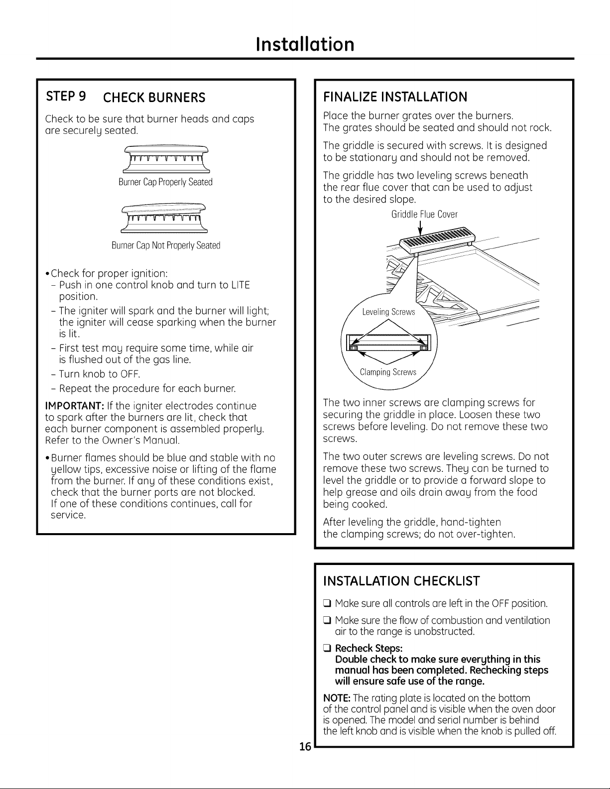
STEP9 CHECK BURNERS
Check to be sure that burner heads and caps
are securely seated.
BurnerCapProperlySeated
)
BurnerCapNotProperlySeated
• Check for proper ignition:
- Push in one control knob and turn to LITE
position.
- The igniter will spark and the burner will light;
the igniter will cease sparking when the burner
is lit.
- First test may require some time, while air
is flushed out of the gas line.
- Turn knob to OFF.
- Repeat the procedure for each burner.
IMPORTANT: Ifthe igniter electrodes continue
to spark after the burners are lit, check that
each burner component is assembled properly.
Refer to the Owner's Manual.
FINALIZE INSTALLATION
Place the burner grates over the burners.
The grates should be seated and should not rock.
The griddle is secured with screws. It is designed
to be stationary and should not be removed.
The griddle has two leveling screws beneath
the rear flue cover that can be used to adjust
to the desired slope.
GriddleFlueCover
_Screws
The two inner screws are clamping screws for
securing the griddle in place. Loosen these two
screws before leveling. Do not remove these two
screws.
• Burner flames should be blue and stable with no
yellow tips, excessive noise or lifting of the flame
from the burner. If any of these conditions exist,
check that the burner ports are not blocked.
If one of these conditions continues, call for
service.
The two outer screws are leveling screws. Do not
remove these two screws. They can be turned to
level the griddle or to provide a forward slope to
help grease and oils drain away from the food
being cooked.
After leveling the griddle, hand-tighten
the clamping screws; do not over-tighten.
INSTALLATION CHECKLIST
Make sure oil controls ore left in the OFF position.
Make sure the flow of combustion and ventilation
air to the range is unobstructed.
Recheck Steps:
Double check to moke sure everything in this
monuol hos been completed. Rechecking steps
will ensure sofe use of the ronge.
NOTE: The rating plate is located on the bottom
of the control panel and isvisible when the oven door
is opened. The model and serial number is behind
the left knob and isvisible when the knob is pulled off.
16
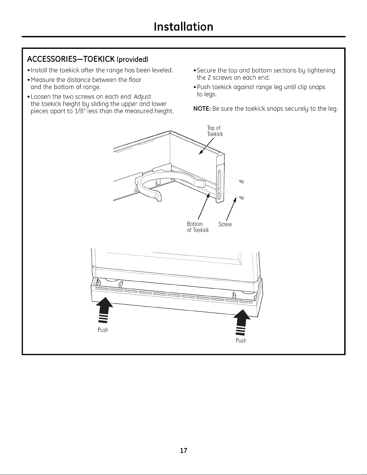
ACCESSORIES--TOEKICK Iprovided)
Installation
• Install the toekick after the range has been leveled.
• Measure the distance between the floor
and the bottom of range.
• Loosen the two screws on each end. Adjust
the toekick height bg sliding the upper and lower
pieces apart to 1/8" less than the measured height.
•Secure the top and bottom sections bg tightening
the 2 screws on each end.
• Push toekick against range leg until clip snaps
to legs.
NOTE: Be sure the toekick snaps securelg to the leg.
Topof
Toekick
Bottom
ofToekick
Screw
Push
Push
17
ZX12B30PSS, ZX12B36PSS, ZX12B48PSS Accessorg Installation
OPTIONAL ACCESSORIES--12" HIGH BACKSPLASH
AWARNING:
To prevent ignition of combustible materials,
the entire back wall above the range must
be protected bg a backsplash constructed
of non-combustible material.
This stainless steel backsplash accessorg
must be installed in combination with a custom,
non-combustible backsplash built beLlond
the 12" height of the backsplash.
BEFOREYOU BEGIN
Read these instructions completelg
end cnrefullg.
IMPORTANT: Seve these instructions for Iocel
inspector's use.
IMPORTANT: OBSERVE ALL GOVERNING CODES
AND ORDINANCES.
NOTE TO INSTALLER: Be sure to leave these
instructions with the Consumer.
NOTE TO CONSUMER: Keep these instructions
with sour Owner's Mnnunl for future reference.
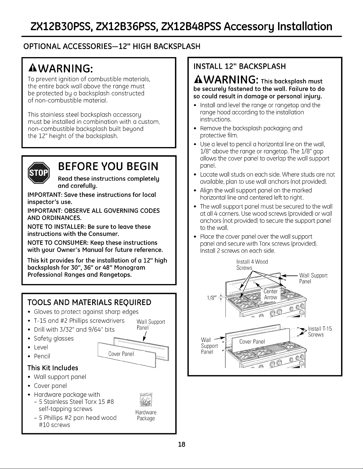
INSTALL 12" BACKSPLASH
.4,WA RNING:Thisbacksplash must
be securelg fastened to the wall. Failure to do
so could result in damage or personal injurg.
• Install and level the range or rangetop and the
range hood according to the installation
instructions.
• Remove the backsplash packaging and
protective film.
• Usea level to pencil a horizontal line on the wall,
1/8" above the range or rangetop. The 1/8" gap
allows the cover panel to overlap the wall support
panel.
• Locate wall studs on each side. Where studs are not
available, plan to use wall anchors (not provided).
• Align the wall support panel on the marked
horizontal line and centered left to right.
• The wall support panel must be secured to the wall
at all 4 corners. Usewood screws (provided) or wall
anchors (not provided) to secure the support panel
to the wall.
• Place the cover panel over the wall support
panel and secure with Torx screws (provided).
Install 2 screws on each side.
This kit provides for the instellntion of n 12" high
bncksplnsh for 30", 36" or 48" Monogrnm
Professionel Renges end Rengetops.
TOOLS AND MATERIALS REQUIRED
• Gloves to protect against sharp edges
• T-15 and #2 Phillips screwdrivers Wall Support
• Drill with 3/32" and 9/64" bits Panel
• Pencil
•" SafetgLevelglasses
This Kit Includes
• Wall support panel
• Cover panel
• Hardware package with
- 5 Stainless Steel Torx 15 #8
self-tapping screws
- 5 Phillips #2 pan head wood
#10 screws
Hardware
Package
/8 :r--
Wall
Support
Panel
Install4 Wood
Screws
Wall Support
Panel
.... _ InstallT-15
o_" Screws
CoverPanel
18
ZXADJB30PSS,ZXADJB36PSS,ZXADJB48PSSAccessorg Installation
ACCESSORIES--30" TO 36" ADJUSTABLE BACKSPLASH (not included)
- WARNING:
To prevent ignition of combustible materials,
the entire back wall above the range must
be protected by a backsplash constructed
of non-combustible material.
BEFORE YOU BEGIN
Read these instructions completely
and carefully.
IMPORTANT: Save these instructions for local
inspector's use.
IMPORTANT: OBSERVEALL GOVERNING CODES
AND ORDINANCES.
NOTETO INSTALLER:Be sure to leave these
instructions with the Consumer.
NOTETO CONSUMER: Keep these instructions
with your Owner's Manual for future reference.
• This backsplash adjusts to fit the space between
the top of the range and the bottom of the hood,
from 30" Min. to 36" Max. height.
• Maximum shelf load-bearing weight is 40 Ibs.
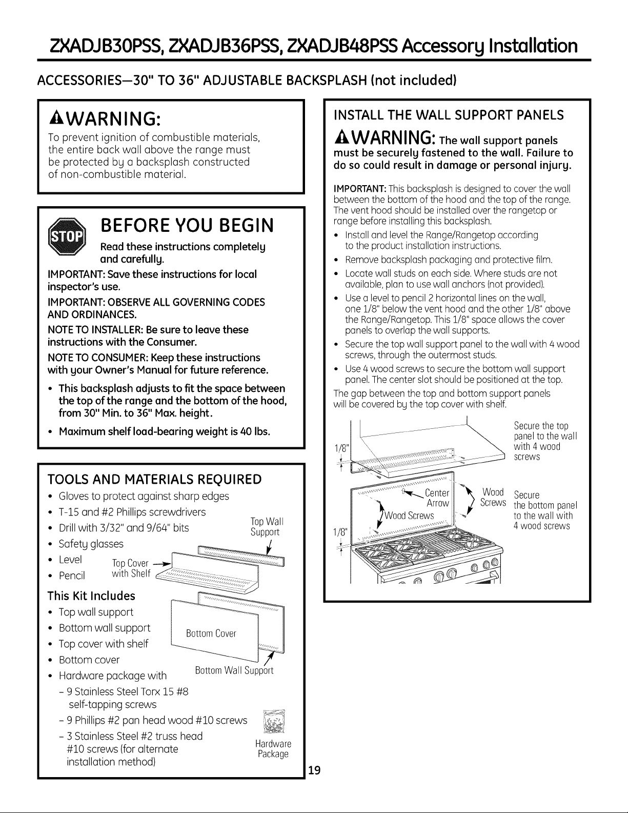
INSTALL THE WALL SUPPORT PANELS
WARNING:The wall support panels
must be securely fastened to the wall. Failure to
do so could result in damage or personal injury.
IMPORTANT:Thisbacksplosh isdesigned to cover the wall
between the bottom of the hood and the top of the range.
The vent hood should be installedover the rongetop or
range before installingthis backsplGsh.
• Installand levelthe Ronge/Rongetop according
to the product installation instructions.
• Removebocksplosh packaging and protective film.
• Locatewall studson each side.Where studsore not
available, plan to usewall anchors (notprovided).
• Usealevelto pencil2 horizontallineson the wall,
one 3_/8"below the vent hood and the other 1/8" above
the Range/Rangetop.This1/8" space allows the cover
panels to overlap the wall supports.
• Securethe top wall support panelto the wall with 4 wood
screws,through the outermost studs.
• Use4wood screwsto securethe bottom wall support
panel.The center slot should bepositioned at the top.
The gap between the top and bottom support panels
will be covered bg the top cover with shelf.
Securethe top
paneltothe wall
with 4 wood
screws
TOOLS AND MATERIALS REQUIRED
• Gloves to protect against sharp edges
• T-1S and #2 Phillips screwdrivers
• Drill with 3/32" and 9/64" bits
• Safety glasses
• Level TopCover
• Pencil with Shelf
This Kit Includes
• Top wall support
• Bottom wall support
• Top cover with shelf
• Bottom cover
• Hardware package with
- 9 Stainless Steel Torx 15 #8
self-tapping screws
- 9 Phillips #2 pan head wood #10 screws
- 3 Stainless Steel #2 truss head
#10 screws (for alternate
installation method)
BottomWall Support
TopWall
Support
Hardware
Package
19
Wood
Screws
Secure
the bottompanel
to the wall with
4 woodscrews
?_XADJB30PSS,ZXADJB36PSS,ZXADJB48PSSAccessorg Installation
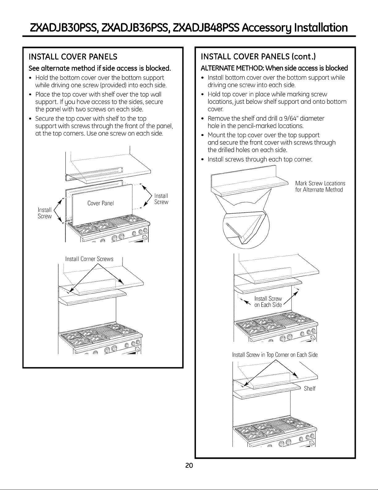
INSTALL COVER PANELS
See alternate method if side access is blocked.
• Hold the bottom cover over the bottom support
while driving one screw (provided)into each side.
• Place the top cover with shelf over the top wall
support. If you have access to the sides, secure
the panel with two screws on each side.
• Secure the top cover with shelf to the top
support with screws through the front of the panel,
at the top corners. Use one screw on each side.
Install
Screw
Install
Screw
INSTALL COVER PANELS (cont.)
ALTERNATE METHOD: When side access is blocked
• Instoll bottom cover over the bottom support while
driving one screw into eoch side.
• Hold top cover in ploce while morking screw
Iocotions,just below shelf support ond onto bottom
cover.
• Remove the shelf ond drill o 9/64" diometer
hole in the pencil-morked Iocotions.
• Mount the top cover over the top support
ond secure the front cover with screws through
the drilled holes on eoch side.
Instoll screws through eoch top corner.
MarkScrewLocations
forAlternateMethod
InstallCornerScrews
"- InstallScrew
"_- onEachSide
InstallScrewinTopCorneronEachSide
Shelf
2O
Convert Natural Gas to LP Gas Operation
JIlnstallat.ionnstructlons I
Convert LP Gas to Natural Gas Operation
-AWARNING:Thisconversionmust
be performed by a qualified installer or gas supplier
in accordancewith the manufacturer's instructions
and all codes and requirements of the authority having
jurisdiction. Failure to follow instructions could result
in serious injury or property damage. Thequalified
agency performing this work assumes responsibility
for the conversion.
-AWARNING:The rangetop, as shipped from
the factorg, is set for usewith its intended gas. If gou
wish to use gour rangetop with the alternate gas, gou
must first replace the orifices and convert the pressure
regulator.
-AWARNING:Thefollowing adjustments
must be made before turning on the burner. Failureto
do socould result in serious injurg. Be sure pressure
regulator has been converted as described in Step 2.
TOOLS YOU NEEDED FOR CONVERSION
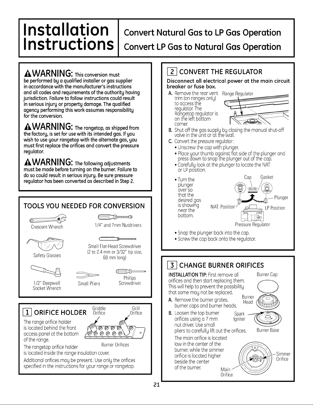
CONVERT THE REGULATOR
Disconnect all electrical power at the main circuit
breaker or fuse box.
A. Removethe rearvent RangeRegulator
trim (on rangesonlg)
to accessthe
regulator.The .
Rangetop.regulator is
on the left bottom
corner.
B. Shut offl_hegassupplLIbg closingthe manual shut-off
vave inthe unit or at the wall.
C. Convertthe pressureregulator:
• Unscrewthe capwith plunger.
• Placeyour thumb against flat sideofthe plunger and
pressdown to snap the plunger out at the cap.
• Carefullglookat the plunger to locate the NAT
or LPposition.
• Turnthe
plunger
overso
that the
desiredgas
isshowing
nearthe
bottom.
Position_ LPPosition
Cap G,asket
@=/@
_ _--IPlunger
.....
CrescentWrench
SafetyGlasses
1/2" Deepwell
SocketWrench
SmallPliers Screwdriver
ORIFICE HOLDER
Therange orifice holder
islocated behindthe front
access panel at the bottom
of the range.
Therangetop orifice holder BurnerOrifices
islocated insidethe range insulation cover.
Additional orifices may be present. Useonlgthe orifices
specifiedin the instructions for gour range or rangetop.
1/4"and7mmNutdrivers
r_
SmallFlat-HeadScrewdriver
(2to 2.4mmor 3/32"tip size,
60mmlong)
Philips
Griddle Grill
Orifice Orifice
PressureRegulator
• Snapthe plunger back into the cap.
• Screwthe cap back onto the regulator.
_-I CHANGE BURNER ORIFICES
INSTALLATIONTIP:First removeall
orificesand then start replacing them.
Thiswill helpto prevent the possibilitg
that some mag not be replaced.
A.
Removethe burner grates, Head
burner caps and burner heads.
B.
Loosenthe top burner Spark __
orificesusing a 7 mm Igniter
nut driver.Usesmall
pliersto carefullg lift out the orifices. BurnerBase
Themain orifice islocated
low in the center of the
burner,while the simmer
orifice islocated higher
besidethe center
of the burner. Main
Orifice
BurnerCap
Burner
Orifice
21
 Loading...