


GE PDW9200, PDW8100, PDW8600, PDW8500, PDW8700 User Manual
...Installation
Instructions
Built-In
Dishwasher
If you have questions, call 800-GECARES or visit our website at: www.GEAppliances.com
BEFORE YOU BEGIN
Read these instructions completely and carefully.
IMPORTANT –
governing codes and ordinances.
•Note to Installer – Be sure to leave these instructions for the consumer’s and local inspector’s use.
•Note to Consumer – Keep these instructions with your Owner’s Manual for future reference.
•Skill Level – Installation of this dishwasher requires basic mechanical and electrical skills. Proper installation is the responsibility of the installer. Product failure due to improper installation is not covered under the GE Appliance Warranty.
•Completion Time – 1 to 3 Hours. New installations require more time than replacement installations.
IMPORTANT – The dishwasher MUST be installed to allow for future removal from the enclosure if service is required.
If you received a damaged dishwasher, you should immediately contact your dealer or builder.
Optional Accessories – See the Owner’s Manual for available custom panel kits.
FOR YOUR SAFETY
Read and observe all CAUTIONS and WARNINGS shown throughout these instructions. While performing installations described in this booklet, gloves, safety glasses or goggles should be worn.
READ CAREFULLY.
KEEP THESE INSTRUCTIONS.
PDW8100 Series |
PDW8800 Series |
PDW8200 Series |
PDW9200 Series |
PDW8500 Series |
PDW9700 Series* |
PDW8600 Series |
PDW9800 Series |
PDW8700 Series |
|
*For PDW9700 Series also refer to the Instructions provided on the template packed with that model.
Pub. No. 31-30561-1
Dwg. No. 206C1559P101
(N.D. 756) 6/03–Rev.

Installation Preparation
PARTS SUPPLIED:
Two #8 Phillips flat head wood screws, 5/8" long to secure dishwasher to underside of countertop or sides of cabinetry. (Taped to top or side of dishwasher.)
Side and top trim pieces
Trim Panel Accessory Kit (not shown). Model PDW9700 only
Drain Hose and Hose Clamp
2 Wood Screws
Trim Pieces (some models)
Drain Hose |
Hose Clamp |
|
MATERIALS YOU WILL NEED :
Ferrule, compression nut and 90° Elbow (3/8"NPT external thread on one end, opposite end sized to fit water supply)
Thread seal tape
UL Listed wire nuts (3)
Materials For New Installations Only:
|
Hand |
Wire Nuts (3) |
90° Elbow, |
Shut-Off |
Thread |
Ferrule and |
Valve |
Seal Tape |
Compression Nut |
|
|
Air gap for drain hose, if required |
|
Electrical Cable |
|
|
Waste tee for house plumbing, if applicable |
|
Hot Water line |
||
Electrical cable or power cord, if applicable |
|
(or Power Cord, if applicable) |
||
|
|
|
||
Screw type hose clamps |
|
|
|
|
Strain relief for electrical connection. |
|
|
|
|
Hand shut-off valve |
Waste Tee |
|
Coupler |
|
Water line 3/8" min. copper |
Screw Type |
|||
|
Strain Relief |
|||
Coupler for extending drain line, if applicable |
Air Gap |
Hose Clamps |
||
|
||||
TOOLS YOU WILL NEED:
Phillips head screwdriver |
Phillips |
|
Head |
||
5/16" and 1/4" nutdriver |
||
Screwdriver |
||
6" Adjustable wrench |
||
|
||
Level |
|
|
Carpenters square |
|
|
Measuring tape |
|
Safety glasses |
15/16" Socket |
|
Flashlight |
||
|
||
Bucket to catch water when flushing the line |
||
15/16" socket (optional for skid removal) |
Flashlight |
|
Gloves |
||
|
||
For New Installations Only:
Tubing cutter
Drill and appropriate bits |
|
|
Hole saw set |
Gloves |
Bucket |
|
Level |
1/4" |
|
and 5/16" |
|
Nutdriver |
|
|
Carpenters |
6" Adjustable |
Square |
Wrench |
|
|
Tubing Cutter |
|
Measuring Tape |
Safety Glasses |
|
Drill and Bits
Hole Saw Set
2
Installation Preparation
PREPARE DISHWASHER ENCLOSURE
|
|
This Wall Area |
|
|
|||
|
|
must be Free of |
|
|
|||
34-1/2"± 1/4" |
Pipes or wires |
24" |
|
||||
|
|
|
|
||||
Underside of |
5" |
4" |
5" |
4" Min. |
|
||
|
Countertop |
|
|
|
|
|
|
|
to Floor |
|
|
|
|
Cabinets |
|
|
|
|
|
|
|
||
|
|
|
|
|
6" |
Square |
|
|
|
|
|
|
and |
||
|
|
|
24" Min. |
|
|
Plumb |
|
|
|
|
|
|
|
||
|
Floor MUST |
|
|
|
|
||
Figure A |
be Even with |
Plumbing and Electric Service |
|||||
Room Floor |
Must Enter Shaded Area |
||||||
|
|||||||
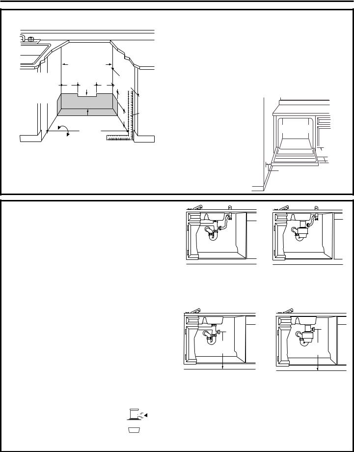
•The rough cabinet opening must be at least 24" deep, 24" wide and approximately 34-1/2" high from floor to underside of the countertop.
•The dishwasher must be installed so that drain hose is no more than 10 feet in length for proper drainage.
 WARNING
To reduce the risk of electric shock, fire, or injury to persons, the installer must ensure that the dishwasher is completely enclosed at the time of installation.
CLEARANCES: When installed into a corner, allow 2" min. clearance between dishwasher and adjacent cabinet, wall or other appliances. Allow 28-3/8" min. clearance from the front of the dishwasher for door opening. Figure B
Countertop
Dishwasher
28-3/8"
Clearance for Door Opening 2" Minimum
Figure B
DRAIN REQUIREMENTS
•Follow local codes and ordinances.
•Do not exceed 10 feet distance to drain.
•Do not connect drain lines from other devices to the dishwasher drain hose.
NOTE: This dishwasher is equipped with a high drain loop. There is no minimum height required for drain hose routing. However, 18" minimum from floor to center of waste tee or disposer inlet is required. See Figure D.
DETERMINE DRAIN METHOD
The type of drain installation depends on the following question.
Do local codes or ordinances require an air gap?
Is waste tee less than 18" above floor?
If the answer to either question is YES, Method 1 MUST be used.
• If the answers are NO, either method may be used.
CABINET PREPARATION
•Drill a 1-1/2" dia. hole in the cabinet wall within the shaded areas shown in Figure A for the drain hose connection. The hole should be smooth with no sharp edges.
IMPORTANT: When connecting |
|
|
|
|
|
Remove |
||
|
|
|
|
|||||
drain line to disposer, check to be |
|
|
|
|
|
Hopper |
||
|
|
|
|
|
||||
sure that drain plug has been |
|
|
|
|
Plug |
|||
removed. DISHWASHER WILL NOT |
|
|
|
|
||||
DRAIN IF PLUG IS LEFT IN PLACE. |
|
|
|
|
||||
Figure C
Method 1 – Air Gap with Waste Tee or Disposer
An air gap must be used when required by local codes and ordinances. The air gap must be installed according to manufacturers instructions.
18" |
18" |
Min. |
Min. |
Figure D
Method 2 – Built-in “High Drain Loop” with Waste Tee or Disposer
3
Installation Preparation
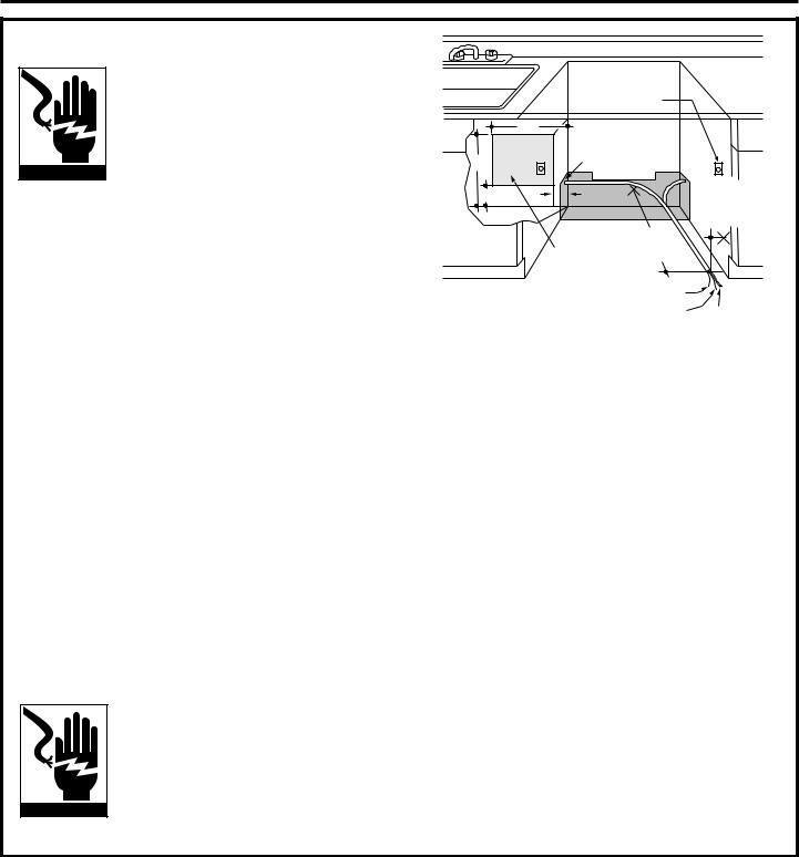
PREPARE ELECTRICAL WIRING
WARNING
FOR PERSONAL SAFETY: Remove house fuse or open circuit breaker before beginning installation. Do not use an extension cord or adapter plug with this appliance.
Electrical Requirements
•This appliance must be supplied with 120V, 60 Hz., and connected to an individual properly grounded branch circuit, protected by a 15 or 20 ampere circuit breaker or time delay fuse.
•Wiring must be 2 wire with ground and rated for 75° C (176° F).
•If the electrical supply does not meet the above requirements, call a licensed electrician before proceeding.
Grounding Instructions–Cable Direct
This appliance must be connected to a grounded metal, permanent wiring system, or an equipment grounding conductor must be run with the circuit conductors and be connected to the equipment grounding terminal or lead on the appliance.
Grounding Instructions–Power Cord Models
This appliance must be grounded. In the event of a malfunction or breakdown, grounding will reduce the risk of electric shock by providing a path of least resistance for electric current. This appliance is equipped with a cord having an equipment grounding conductor and a grounding plug. The plug must be plugged into an appropriate outlet that is installed and grounded in accordance with all local codes and ordinances.
WARNING
The improper connection of the equipment grounding conductor can result in a risk of electric shock. Check with a qualified electrician or service representative if you are in doubt that the appliance is properly grounded.
|
Alternate |
|
|
|
Receptacle |
|
|
|
Location |
|
|
|
18" |
|
|
|
1-1/2" Dia. |
|
|
18" |
Hole (Max.) |
|
|
|
|
|
|
6" |
6" |
|
3" |
|
from |
||
|
|
24" |
Cabinet |
|
|
|
|
|
Receptacle |
from Wall |
|
|
Location |
|
|
|
Area |
Ground |
|
Figure E |
|
Black |
White |
For models equipped with power cord: Do not modify the plug provided with the appliance; if it will not fit the outlet, have a proper outlet installed by a qualified technician.
Cabinet Preparation & Wire Routing
•The wiring may enter the opening from either side, rear or the floor within the shaded area.
•Cut a 1-1/2" max. dia. hole to admit the electrical cable. Cable direct connections may pass through the same hole as the drain hose and hot water line, if convenient. If cabinet wall is metal, the hole edge must be covered with a bushing. NOTE: Power cords with plug must pass through a separate hole.
Electrical Connection to Dishwasher
Electrical connection is on the right front of dishwasher.
•For cable direct connections the cable must be routed as shown in Figure E. Cable must extend a minimum of 24" from the rear wall.
•For power cord connections, install a 3-prong grounding type receptacle in the sink cabinet rear wall, 6" min. or 18" max. from the opening, 6" to 18" above the floor.
4
 Loading...