

GE GTD18ESSJ2WW, GTD18GSSJ2WW, GTD42EASJ0WW, GTD42EASJ1WW, GTD42GASJ0WW Installation Guide
...
Installati
n
Dryers
Instructi
i Ouestions? Call800.GE.CARES {800.432.2737)orvisitour Web siteat:GEAppliances.com i
This isthe safety alert symbol. This symbol alerts you to potential hazards that can kill you or hurt you and others.
A
All safety messages will follow the safety alert symbol and the word "DANGER","WARNING", or "CAUTION".These
words are defined as:
Indicates a hazardoussituation which, if not avoided,will resultin death or seriousinJury.
Indicates a hazardoussituation which, if not avoided, could result indeath or seriousinjury.
Indicates a hazardoussituation which, if not avoided, could result inminor or moderate injury.
BEFORE YOU BEGIN
Readthese instructions completely and carefully.
• IMPORTANT-save these instructions for local
electrical inspector's use.
• IMPORTANT- Observeallgoverning codesand
ordinances.
• Installthe clothes dryer according to the manufacturer's
instructions and local codes.
• Note to Installer - Be sure to leavethese instructions
with the Consumer.
• Note to Consumer - Keepthese instructions for future
reference.
• Clothes dryer installation must be performed by a
qualified installer.
• Thisdryer must be exhausted to the outdoors.
• Before the old dryer is removed from service or
discarded, remove the dryer door.
• Service information and the wiring diagram are located
in the control console.
• Do not allow children on or inthe appliance. Close
supervision of children isnecessary when the appliance
is used near children.
• Proper installation isthe responsibility of the installer.
• Product failure due to improper installation is not
covered under the Warranty.
• Install the dryer where the temperature is above 50°F
for satisfactory operation of the dryer control system.
• Remove and discard existing plastic or metal foil duct
and replace with UL-listed duct.
as
- Fire Hazard
• Clothes dryer installation must be performed by a
qualified installer.
Install the clothes dryer according to these
instructions and local codes.
DO NOT install a clothes dryer with flexible plastic
venting materials. If flexible metal (semi-rigid or
foil-type) duct is installed, it must be UL-listed and
installed in accordance with the instructions found
in "Connecting the Dryer to House Vent" later in
this manual. Flexible vent materials are known to
collapse, be easily crushed and trap lint. These
conditions will obstruct dryer airflow and increase
the risk of fire.
DO NOT install or store this appliance in any
location where it could be exposed to water or
weather.
To reduce the risk of severe injury or death, follow
all installation instructions.
Save these instructions. (Installers: Be sure to leave
these instructions with the customer.)
01
Printed in Me×ico
234D2318P001
31-16767-Io5-15GE
Installation Instructions
StateofCaliforniaProposition65 Warnings:
TheCaliforniaSafeDrinkingWater and Toxic EnforcementAct requiresthe governor of Californiato publisha list of substances
known to the state to cause cancer, birth defects or other reproductive harm and requiresbusinessesto warn of potential exposure
to suchsubstances.
Thisproduct contains one or morechemicals known to the Stateof Californiato causecancer, birth defectsor
other reproductive harm.
Gasappliances cancause low-level exposureto some ofthese substances,including benzene,carbon monoxide, formaldehyde and
soot,caused primarily by the incompletecombustion of natural gas or LPfuels. Exposureto these substancescan be minimized by
properlyventing the dryer to the outdoors.
UNPACKING YOUR DRYER
Tilt the dryer sideways and remove the foam
shipping pads by pulling at the sides and breaking
them away from the dryer legs. Be sure to remove all
of the foam pieces around the legs.
Remove literature and bag containing accessories.
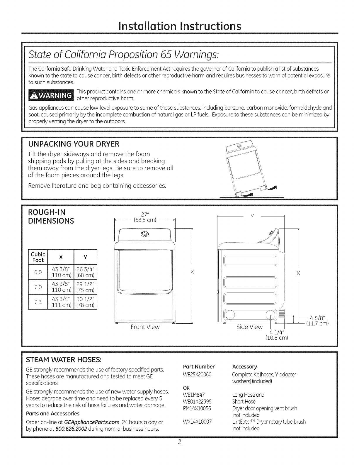
ROUGH-IN 27"
DIMENSIONS ------ (68.8 cm)
Cubic × y
Foot
43 3/8" 26 3/4"
6.0 (110 cm) (68 cm)
43 3/8" 29 1/2"
7.0 (110 cm) (75 cm)
43 3/4" 30 1/2"
7.3 (111cm) (78 cm)
Front View
J
STEAM WATER HOSES:
GEstrongly recommends the useof factory specified parts.
Thesehosesare manufactured andtested to meet GE
specifications.
GEstrongly recommends the useof new water supply hoses.
Hosesdegrade overtime and need to bereplaced every 5
years to reducethe risk of hose failures and water damage.
Parts end Accessories
Order on-line at GEAppliencePorts.com, 24 hours a day or
by phone at 800.626.2002during normal businesshours.
Pert Number
WE25X20060
OR
WEltq847
WE01X22395
plVll4X100%
WX14X10007
Y
.................. -4--
%
Side View \_
4 1/4"
(10.8cm)
Accessory
CompleteKit(hoses,Y-adapter
washers)(included)
LongHoseand
ShortHose
Dryerdooropeningventbrush
(notincluded)
LintEaterTM Dryerrotarytube brush
(notincluded)
X
_14 s/8"
1.7 cm)
Installation Instructions
REQUIREMENTS FOR ALCOVE OR
CLOSET INSTALLATION
_- Explosion Hazard
Keepflammable materials and vapors, such as gasoline,
away from dryer.
Placedryer at least 18" (/46cm) above the floor for a
garage installation.
Failureto do so can result in death, explosion, or fire.
,, If the dryer is approved for installation in an alcove or
closet, it will be stated on a label on the dryer back.
• The dryer MUST be vented to the outdoors. See
the EXHAUSTING THE DRYERsection.
• Minimum clearance between dryer cabinet and
adjacent walls or other surfaces is:
0" either side
3" front
0" rear but a 1" minimum is recommended
Minimum vertical space from dryer to overhead
shelves, cabinets, ceilings, etc., is 1" on top.
Consideration must be given to provide adequate
clearance for installation and service.
Closet doors must be Iouvered or otherwise
ventilated and have at least 60 square inches of
open area. If the closet contains both a washer
and a dryer, doors must contain a minimum of
120 square inches of open area.
NOTE: WHEN THE EXHAUST DUCT IS LOCATED IN
THE REAR OF THE DRYER,THE CONFIGURATION OF
THE DUCTING MAY REQUIRE GREATER THAN 0" OF
REARCLEARANCE.A 1" MINIMUM ISRECOMMENDED.
Gas Dryers Only:
• No other fuel burning appliance shall be installed
in the same closet as a gas dryer.
The dryer must be disconnected from the gas
supply piping during pressure testing at pressures
greater than 1_ psi (3.5 kPa).
A 1/8 inch NPT minimum plugged tapping,
accessible for test gauge connection, must be
installed immediately upstream of the gas supply
connection to the dryer.
MINIMUM CLEARANCE OTHER THAN
ALCOVE OR CLOSET INSTALLATION
Minimum clearance to combustible surfaces and
for air opening are: 0" both sides; 1" front; 0" rear
but a 1" minimum is recommended. Consideration
must be given to provide adequate clearance for
installation and service.
MOBILE OR MANUFACTURED HOME
INSTALLATION
• Installation must conform to the
MANUFACTURED HOME CONSTRUCTION AND
SAFETYSTANDARD, TITLE 2/4, PART 32-80 or
Standard CAN/CSA-Z240 MH, or, when such
standard is not applicable, with AMERICAN
NATIONAL STANDARD FOR MOBILE HOME,
ANSI/NFPA NO. 501B.
The dryer MUST be vented to the outdoors. The
exhaust vent must be securely fastened to a
non-combustible portion of the mobile home.
The vent MUST NOT be terminated beneath a
mobile or manufactured home.
• The vent duct material MUST BE METAL.
• KIT 14-D346-33 MUST be used to attach the dryer
securely to the structure.
• The vent MUST NOT be connected to any other
duct, vent or chimney.
• Do not use sheet metal screws or other
fastening devices which extend into the interior
of the exhaust vent.
• Provide an opening with a free area of at least
25 square inches for introduction of outside air
into the dryer room.
• See the sections for electrical connection
information.
POWER CORDS:
GEstrongly recommends the useof factory specified parts.
Selectthe power cord to fit your installation requirements.
Order on-line at GEApplianceParts.com, 24 hours a day or
by phone at 800.626.2002during normal businesshours.
Part Number Type Length Amperage
WX9X2 ]5-Prong 4 Feet 30
WX9X3 3-Prong 5 Feet 30
WX9X4 3-Prong 6 Feet 30
WX9X!8 4-Prong 4 Feet 30
WX9X!9 4-Prong 5 Feet 30
WX9X20 4-Prong 6 Feet 30
Installation Instructions
CONNECTING INLET HOSES
CONNECTING INLET HOSES
(on some models)
To produce steam, the dryer must connect to
the cold water supply. Since the washer must
also connect to the cold water, a "Y" connector
is inserted to allow both inlet hoses to make that
connection at the same time.
NOTE: Use the new inlet hoses provided; never use
old hoses.
,
Turn the cold water faucet off. Remove the
washer inlet hose from the washer fill valve
connector (cold).
.
Ensure the rubber flat washer is in place and
attach one female coupling of the short hose
onto the washer fill valve connector. Tighten by
hand until firmly seated.
.
Attach one male end of the "Y" connector to the
other female coupling of the short hose. Ensure
the rubber flat washer is in place. Tighten by
hand until firmly seated.
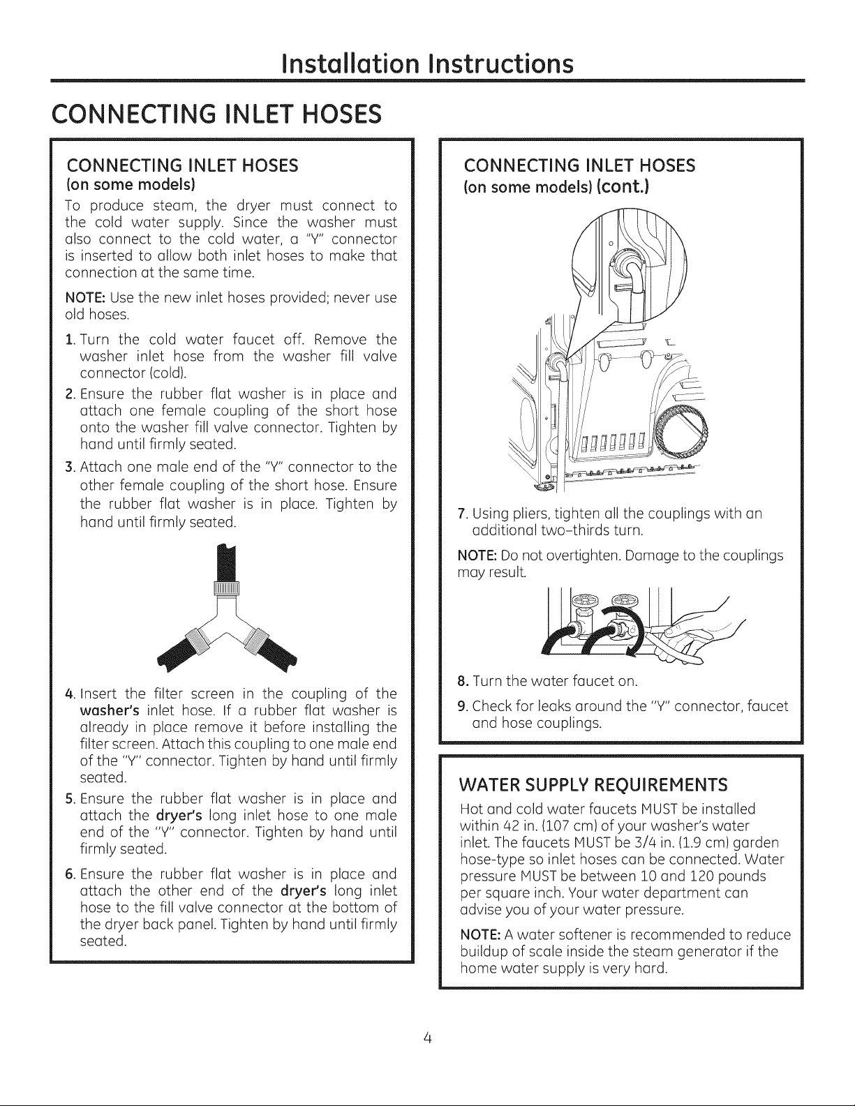
CONNECTING INLET HOSES
Ion some models)(cont.}
7. Using pliers, tighten all the couplings with an
additional two-thirds turn.
NOTE: Do not overtighten. Damage to the couplings
may result.
.
Insert the filter screen in the coupling of the
washer's inlet hose. If a rubber flat washer is
already in place remove it before installing the
filter screen. Attach this coupling to one male end
of the "Y" connector. Tighten by hand until firmly
seated.
S.
Ensure the rubber flat washer is in
attach the dryer's long inlet hose to
end of the "Y" connector. Tighten by
place and
one male
hand until
firmly seated.
.
Ensure the rubber flat washer is in
attach the other end of the dryer's
hose to the fill valve connector at the
the dryer back panel. Tighten by hand
place and
long inlet
bottom of
until firmly
seated.
8. Turn the water faucet on.
9. Check for leaks around the "Y" connector, faucet
and hose couplings.
WATER SUPPLY REQUIREMENTS
Hot and cold water faucets MUST be installed
within 42 in. (107 cm) of your washer's water
inlet. The faucets MUST be 3/4 in. (1.9 cm) garden
hose-type so inlet hoses can be connected. Water
pressure MUST be between 10 and 120 pounds
per square inch. Your water department can
advise you of your water pressure.
NOTE: A water softener is recommended to reduce
buildup of scale inside the steam generator if the
home water supply is very hard.
Installation Instructions
CONNECTING A GAS DRYER(ski
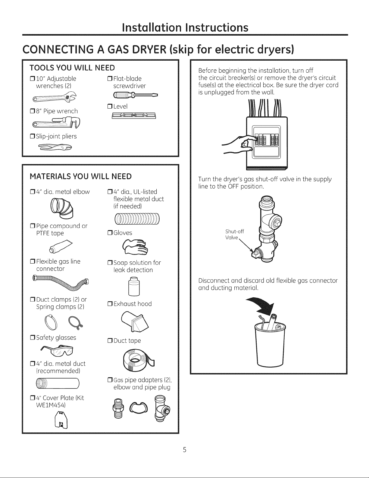
TOOLS YOU WILL NEED
010" Adjustable 0 Flat-blade
wrenches (2) screwdriver
17Level
178" Pipe wrench
17Slip-joint pliers
MATERIALS YOU WILL NEED
174" dia. metal elbow
174" dia., UL-listed
flexible metal duct
(if needed)
) for electric dryers}
Before beginning the installation, turn off
the circuit breaker(s) or remove the dryer's circuit
fuse(s) at the electrical box. Be sure the dryer cord
is unplugged from the wall.
Turn the dryer's gas shut-off valve in the supply
line to the OFF position.
17Pipe compound or
PTFEtape
13Flexible gas line
connector
17Duct clamps (2) or
Spring clamps (2)
%
0 Safety glasses
174" dia. metal duct
(recommended)
)
174" Cover Plate (Kit
WE1H454)
17Gloves
17Soap solution for
leak detection
0 Exhaust hood
17Duct tape
17Gas pipe adapters (2),
elbow and pipe plug
@o
Shut-off
Valve
Disconnect and discard old flexible gas connector
and ducting material.
Installation Instructions
CONNECTING A GAS DRYER(ski
GAS REQUIREMENTS
_ Explosion Hazard
Use a new CSA International approved flexible
gas supply line. Never reuse old flexible
connectors.
o
Install a shut-off valve.
o
Securely tighten all gas connections.
o
If connected to LPgas, have a qualified person
make sure gas pressure does not exceed 13"
water column.
• Examples of a qualified person include: licensed
heating personnel, authorized gas company
personnel, and authorized service personnel.
Failure to do so can result in death, explosion,
or fire.
This gas dryer is equipped with a valve and
burner assembly for use only with natural gas.
Using conversion kit WE2SX217,your local service
organization can convert this dryer for use with
propane (LP)gas. (To convert from propane (LP)
to natural gas, conversion kit WE25X218 will be
utilized.) ALL CONVERSIONS MUST BE MADE BY
PROPERLYTRAINED AND QUALIFIED PERSONNEL
AND IN ACCORDANCEWITH LOCALCODESAND
ORDINANCE REQUIREMENTS.
DRYER GAS SUPPLY CONNECTION
for electric dryers)(cont.)
GAS SUPPLY
A 1/8" National Pipe Taper thread plugged
tapping, accessible for test gauge connection,
must be installed immediately upstream of the
gas supply connection to the dryer. Contact
your local gas utility should you have questions
on the installation of the plugged tapping.
Supply line is to be 1/2" rigid pipe and equipped
with an accessible shutoff within 6 feet of, and
in the same room with, the dryer.
Use pipe thread compound appropriate for
natural or LP gas or use PTFEtape.
Connect flexible metal connector to dryer and
gas supply.
The installation must conform with local codes,
or in the absence of local codes, with the
National Fuel Gas Code, ANSI Z223.1/NFPA 54,
or the Natural Gas and Propane Installation
Code, CSA B149.1.
IN THE COMMONWEALTH OF
MASSACHUSETTS
This product must be installed by a licensed
plumber or gas fitter.
When using ball-type gas shut-off valves, they
shall be the T-handle type.
A flexible gas connector, when used, must not
exceed 3 feet.
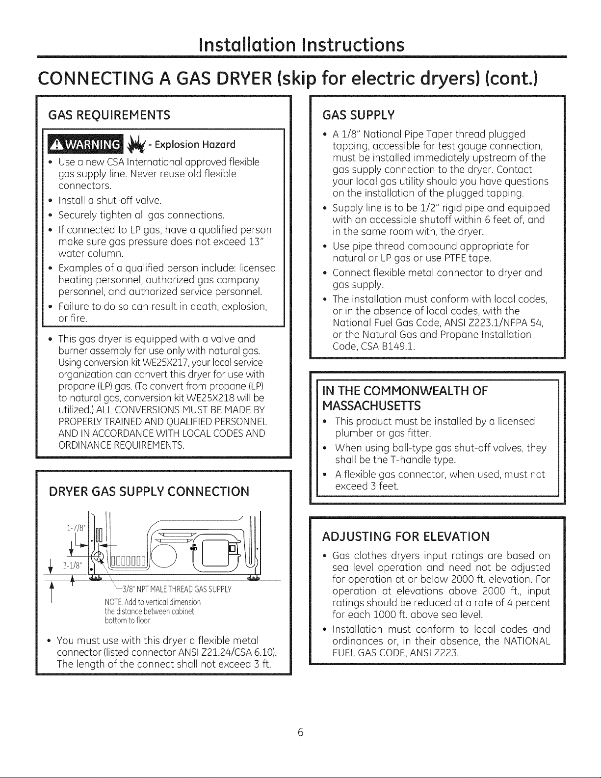
1-7/8"
3-1/8"
3/8"NPTMALETHREADGASSUPPLY
NOTE:Addtoverticabdimension
thedistancebetweencabinet
bottomtofloor.
You must use with this dryer a flexible metal
connector (listed connector ANSI Z21.24/CSA 6.10).
The length of the connect shall not exceed 3 ft.
ADJUSTING FOR ELEVATION
Gas clothes dryers input ratings are based on
sea level operation and need not be adjusted
for operation at or below 2000 ft. elevation. For
operation at elevations above 2000 ft., input
ratings should be reduced at a rate of 4 percent
for each 1000 ft. above sea level.
Installation must conform to local codes and
ordinances or, in their absence, the NATIONAL
FUEL GAS CODE, ANSI Z223.
Installation Instructions
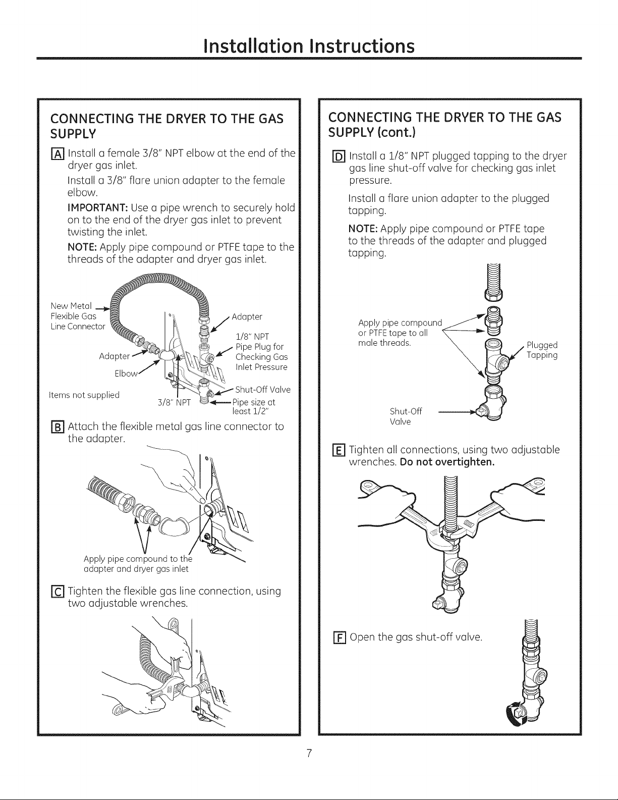
CONNECTING THE DRYER TO THE GAS
SUPPLY
Install a female 3/8" NPT elbow at the end of the
@
dryer gas inlet.
Install a 3/8" flare union adapter to the female
elbow.
IMPORTANT: Use a pipe wrench to securely hold
on to the end of the dryer gas inlet to prevent
twisting the inlet.
NOTE: Apply pipe compound or PTFEtape to the
threads of the adapter and dryer gas inlet.
New Metal
Flexible Gas _
LineConnector ___. _
AdGpter_ _ _
Elbow _
Items not supplied
r_ Attach the flexible metal gas line connector to
the adapter.
3/8" NPT
_pj Adapter
1/8" NPT
Pipe Plug for
Checking Gas
Inlet Pressure
Shut-Off Valve
ipe size at
least !/2"
CONNECTING THE DRYERTO THE GAS
SUPPLY(cont.)
@Install a 1/8" NPT plugged tapping to the dryer
gas line shut-off valve for checking gas inlet
pressure.
Install a flare union adapter to the plugged
tapping.
NOTE: Apply pipe compound or PTFEtape
to the threads of the adapter and plugged
tapping.
oArPPITYFPitPe;°tm Pa_und_@
male threads. __ W PlaUp_1_dg
r_ Tighten all connections, using two adjustable
wrenches. Do not overtighten.
Apply pipe compound to the
adapter and dryer gas inlet
r_ Tighten the flexible gas line connection, using
two adjustable wrenches.
\
EF1Open the gas shut-off valve.
Installation Instructions
CONNECTING A GAS DRYERIskip for electric dryers)Icont.)
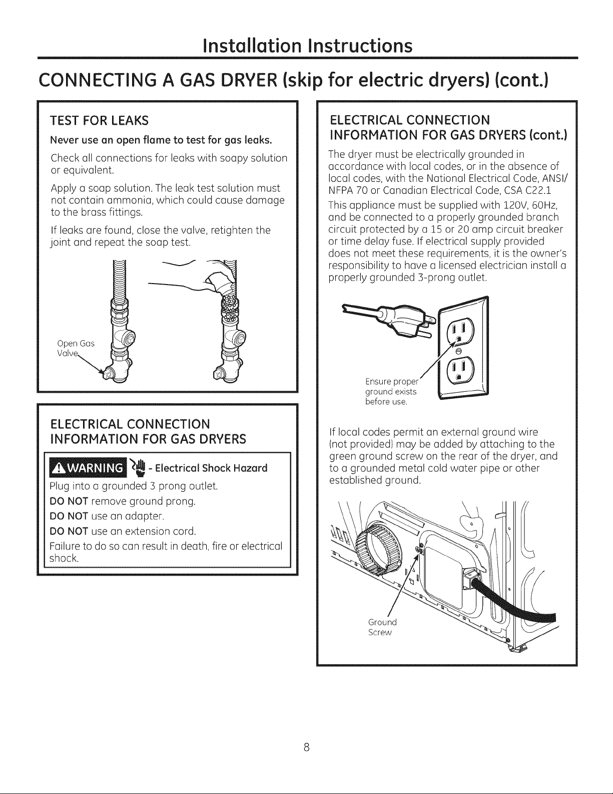
TEST FOR LEAKS
Never use an open flame to test for gas leaks.
Check all connections for leaks with soapy solution
or equivalent.
Apply a soap solution. The leak test solution must
not contain ammonia, which could cause damage
to the brass fittings.
If leaks are found, close the valve, retighten the
joint and repeat the soap test.
Open Gos
ELECTRICAL CONNECTION
INFORMATION FOR GAS DRYERS {cont.}
The dryer must be electrically grounded in
accordance with local codes, or in the absence of
local codes, with the National Electrical Code, ANSI/
NFPA 70 or Canadian Electrical Code, CSA C22.1
This appliance must be supplied with 120V, 60Hz,
and be connected to a properly grounded branch
circuit protected by a 15 or 20 amp circuit breaker
or time delay fuse. If electrical supply provided
does not meet these requirements, it is the owner's
responsibility to have a licensed electrician install a
properly grounded 3-prong outlet.
Ensure proper
ground exists
before use.
ELECTRICAL CONNECTION
INFORMATION FOR GAS DRYERS
_,dL
_ - Electrical Shock Hazard
i
Plug into a grounded 3 prong outlet.
DO NOT remove ground prong.
DO NOT use an adapter.
DO NOT use an extension cord.
Failure to do so can result in death, fire or electrical
shock.
If local codes permit an external ground wire
(not provided) may be added by attaching to the
green ground screw on the rear of the dryer, and
to a grounded metal cold water pipe or other
established ground.
Ground
Screw
Instollotion Instructions
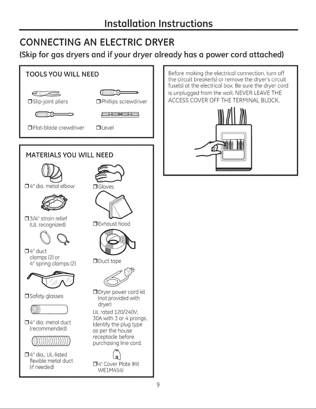
CONNECTING AN ELECTRIC DRYER
(Skip for gos dryers ond if your dryer olreody hos o power cord ottoched)
TOOLS YOU WILL NEED
OSlip-joint pliers 0 Phillips screwdriver
0 Flat-blade crewdriver 0 Level
MATERIALS YOU WILL NEED
04" dia. metal elbow
03/4" strain relief
IUL recognized)
OGIoves
O Exhaust hood
Before making the electrical connection, turn off
the circuit breaker(s) or remove the dryer's circuit
fuse(s) at the electrical box. Be sure the dryer cord
is unplugged from the wall. NEVER LEAVE THE
ACCESS COVER OFF THE TERMINAL BLOCK.
O4" duct
clamps (2)or
4" spring clamps (2)
0 Safety glasses
04" dia. metal duct
(recommended)
O4" dia., UL-listed
flexible metal duct
(if needed)
0 Duct tape
O Dryer power cord kit
(not provided with
dryer)
)
UL rated 120/240V,
30A with 3 or 4 prongs.
Identify the plug type
as per the house
receptacle before
purchasing line cord.
O4" Cover Plate (Kit
WE1H454)
InstallationInstructions
CONNECTING AN ELECTRIC DRYER {cont.}
{Skipforgas dryersand ifyour dryeralreadyhas a power cord attached}
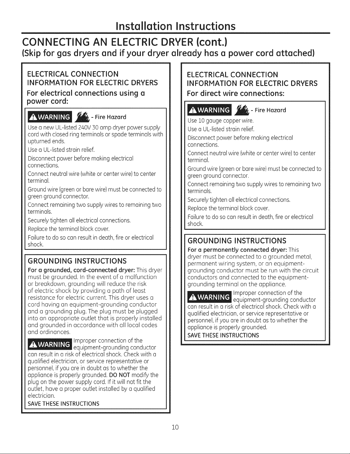
ELECTRICAL CONNECTION
INFORMATION FOR ELECTRIC DRYERS
For electrical connections using a
power cord:
- Fire Hazard
Use a new UL-listed 240V 30 amp dryer power supply
cord with closed ring terminals or spade terminals with
upturned ends.
Use a UL-listed strain relief.
Disconnect power before making electrical
connections.
Connect neutral wire (white or center wire) to center
terminal.
Ground wire (green or bare wire) must be connected to
green ground connector.
Connect remaining two supply wires to remaining two
terminals.
Securely tighten all electrical connections.
Replace the terminal block cover.
Failure to do so can result in death, fire or electrical
shock.
GROUNDING INSTRUCTIONS
For a grounded, cord-connected dryer: This dryer
must be grounded. In the event of a malfunction
or breakdown, grounding will reduce the risk
of electric shock by providing a path of least
resistance for electric current. This dryer uses a
cord having an equipment-grounding conductor
and a grounding plug. The plug must be plugged
into an appropriate outlet that is properly installed
and grounded in accordance with all local codes
and ordinances.
Improper connection of the
equipment-grounding conductor
can result in a risk of electrical shock. Check with a
qualified electrician, or service representative or
personnel, if you are in doubt as to whether the
appliance is properly grounded. DO NOT modify the
plug on the power supply cord. If it will not fit the
outlet, have a proper outlet installed by a qualified
electrician.
SAVE THESE INSTRUCTIONS
ELECTRICAL CONNECTION
INFORMATION FOR ELECTRIC DRYERS
For direct wire connections:
- Fire Hazard
Use 10 gauge copper wire.
Use a UL-Jisted strain relief.
Disconnect power before making electrical
connections.
Connect neutral wire (white or center wire) to center
terminal.
Ground wire (green or bare wire) must be connected to
green ground connector.
Connect remaining two supply wires to remaining two
terminals.
Securely tighten all electrical connections.
Replace the terminal block cover.
Failure to do so can result in death, fire or electrical
shock.
GROUNDING INSTRUCTIONS
For a permanently connected dryer: This
dryer must be connected to a grounded metal,
permanent wiring system, or an equipment-
grounding conductor must be run with the circuit
conductors and connected to the equipment-
grounding terminal on the appliance.
Improper connection of the
equipment-grounding conductor
can result in a risk of electrical shock. Check with a
qualified electrician, or service representative or
personnel, if you are in doubt as to whether the
appliance is properly grounded.
SAVETHESEINSTRUCTIONS
10
Installation Instructions
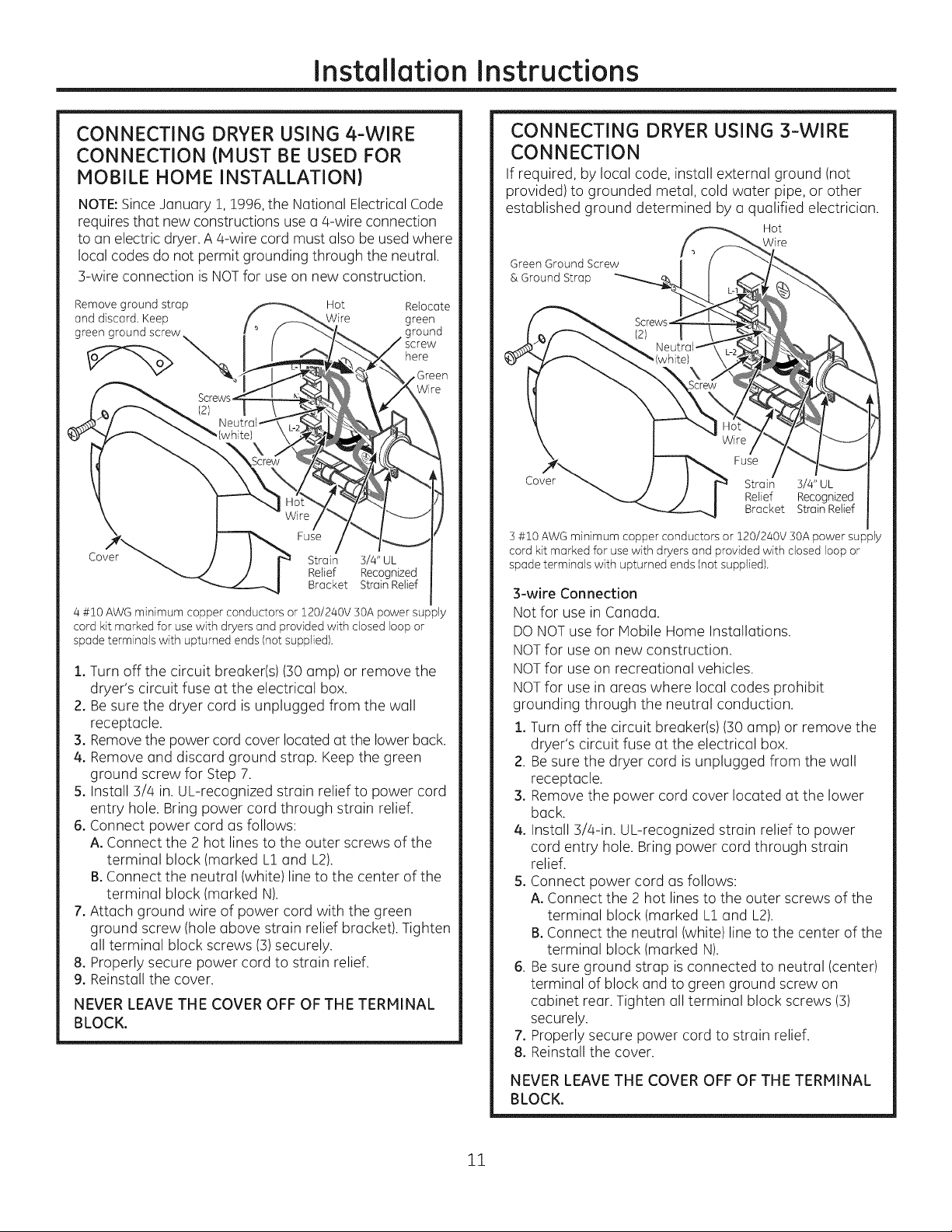
CONNECTING DRYER USING 4-WIRE
CONNECTION (MUST BE USED FOR
MOBILE HOME INSTALLATION)
NOTE:Since January !, !996, the National Electrical Code
requires that new constructions use a q-wire connection
to an electric dryer. A q-wire cord must also be used where
local codes do not permit grounding through the neutral.
3-wire connection is NOTfor use on new construction.
Remove ground strap Hot Relocate
and discard, Keep Wire green
greengroundscrew
here
Fuse
Cover
4 #10 AWG minimum copper conductors or 120/240V 50A power supply
cord kit marked for use with dryers and provided with closed loop or
spade terminals with upturned ends (not supplied).
1. Turn off the circuit breaker(s) (:SOamp) or remove the
dryer's circuit fuse at the electrical box.
2. Be sure the dryer cord is unplugged from the wall
receptacle.
3. Removethe power cord cover located at the lower back.
4. Remove and discard ground strap. Keep the green
ground screw for Step 7.
5. Install 3/4 in. UL-recognized strain relief to power cord
entry hole. Bring power cord through strain relief.
6. Connect power cord as follows:
A. Connect the 2 hot lines to the outer screws of the
terminal block (marked L1and L2).
B.Connect the neutral (white) line to the center of the
terminal block (marked N).
7. Attach ground wire of power cord with the green
ground screw (hole above strain relief bracket). Tighten
all terminal block screws (3)securely.
8. Properly secure power cord to strain relief.
9. Reinstall the cover.
NEVER LEAVE THE COVER OFF OF THE TERMINAL
BLOCK.
Strain 3/4" UL
Relief Recognized
Bracket Strain Relief
CONNECTING DRYER USING 3-WIRE
CONNECTION
If required, by local code, install external ground (not
provided) to grounded metal, cold water pipe, or other
established ground determined by a qualified electrician.
Hot
Wire
Green Ground Screw
& Ground Strap
]
Fuse
Cover
] #10 AWG minimum copper conductors or 120/240V ]OA power supply
cord kit marked for use with dryers and provided with closed loop or
spade terminals with upturned ends (not supplied).
3-wire Connection
Not for use in Canada.
DONOT use for Mobile Home Installations.
NOTfor use on new construction.
NOTfor use on recreational vehicles.
NOTfor use in areas where local codes prohibit
grounding through the neutral conduction.
1. Turn off the circuit breaker(s) (30 amp) or remove the
dryer's circuit fuse at the electrical box.
2. Besure the dryer cord is unplugged from the wall
receptacle.
3. Remove the power cord cover located at the lower
back.
4. Install 3/a-in. UL-recognized strain relief to power
cord entry hole. Bring power cord through strain
relief.
5. Connect power cord as follows:
A. Connect the 2 hot lines to the outer screws of the
terminal block (marked L1and L2).
B.Connect the neutral (white) line to the center of the
terminal block (marked N).
6. Besure ground strap is connected to neutral (center)
terminal of block and to green ground screw on
cabinet rear. Tighten all terminal block screws (3)
securely.
7. Properly secure power cord to strain relief.
8. Reinstall the cover.
Strain 3/4" UL
Relief Recognized
Bracket StrainRelief
NEVER LEAVE THE COVER OFF OF THE TERMINAL
BLOCK.
11
Installation Instructions
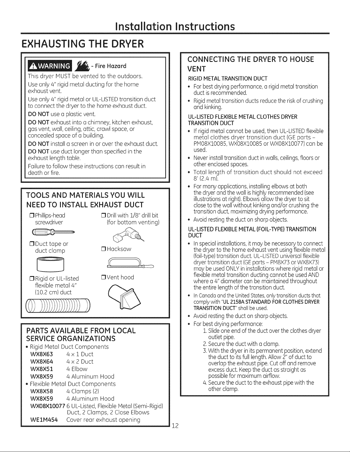
EXHAUSTING THE DRYER
- Fire Hazard
This dryer MUST be vented to the outdoors.
Use only 4" rigid metal ducting for the home
exhaust vent.
Use only 4" rigid metal or UL-LISTEDtransition duct
to connect the dryer to the home exhaust duct.
DO NOT use a plastic vent.
DO NOT exhaust into a chimney, kitchen exhaust,
gas vent, wall, ceiling, attic, crawl space, or
concealed space of a building.
DO NOT install a screen in or over the exhaust duct.
DO NOT use duct longer than specified in the
exhaust length table.
Failure to follow these instructions can result in
death or fire.
TOOLS AND MATERIALS YOU WILL
NEED TO INSTALL EXHAUST DUCT
C1Phillips-head
screwdriver
17Duct tape or
duct clamp
17Rigid or UL-listed
flexible metal 4"
(10.2 cm) duct
17Drill with 1/8" drill bit
(for bottom venting)
C1Hacksaw
17Vent hood
%
PARTS AVAILABLE FROM LOCAL
SERVICE ORGANIZATIONS
• Rigid Metal Duct Components
WXSX63 4 x 1 Duct
WX8X64 4 x 2 Duct
WX8XS1 4 Elbow
WX8×S9 4 Aluminum Hood
Flexible Metal Duct Components
W×8XS8 4 Clamps (2)
WX8×59 4 Aluminum Hood
WX08×::[0077 6 UL-Listed, Flexible Metal (Semi-Rigid)
Duct, 2 Clamps, 2 Close Elbows
WE1H454 Cover rear exhaust opening
CONNECTING THE DRYER TO HOUSE
VENT
RIGID METALTRANSITIONDUCT
Forbest drying performance, a rigid metal transition
duct isrecommended.
Rigidmetal transition ducts reduce the risk of crushing
and kinking.
UL-LISTEDFLEXIBLEMETAL CLOTHESDRYER
TRANSITIONDUCT
If rigid metal cannot be used, then UL-LISTEDflexible
metal clothes dryer transition duct (GEparts -
PIO8XlO085, WXO8XlO085 or WXO8XlO077) can be
used.
• Never install transition duct in walls, ceilings,floors or
other enclosed spaces.
Total length of transition duct should not exceed
8' (2.4 m).
Formany applications, installing elbows at both
the dryer and the wall is highly recommended (see
illustrations at right). Elbows allow the dryer to sit
close to the wall without kinking and/or crushing the
transition duct, maximizing drying performance.
Avoid resting the duct on sharp objects.
UL-LISTEDFLEXIBLEMETAL (FOIL-TYPE)TRANSITION
DUCT
• Inspecial installations, it may be necessary to connect
the dryer to the home exhaust vent using flexible metal
(foil-type) transition duct. UL-LISTEDuniversal flexible
dryer transition duct (GEparts - PM8X73or WX8X73)
may be used ONLYin installations where rigid metal or
flexible metal transition ducting cannot be used AND
where a 4" diameter can be maintained throughout
the entire length of the transition duct.
InCanadaandthe UnitedStates,onlytransition ductsthat
comply with "UL2158ASTANDARDFORCLOTHESDRYER
TRANSITIONDUCT"shall be used.
®
Avoid resting the duct on sharp objects.
®
Forbest drying performance:
1.Slide one end of the duct over the clothes dryer
outlet pipe.
2.Secure the duct with aclamp.
]. With the dryer in its permanent position, extend
the duct to its full length. Allow 2" of duct to
overlap the exhaust pipe. Cut off and remove
excess duct. Keep the duct as straight as
possible for maximum airflow.
4.Secure the duct to the exhaust pipe with the
other clamp.
12
 Loading...