


Service Instructions
Split System Air Conditioners,
Split System Heat Pumps
with R-22 Refrigerant
Blowers, Coils, & Accessories
This manual is to be used by qualified, professionally trained HVAC technicians only. Goodman does not assume any responsibility for property damage or personal injury due to improper service procedures or services performed by an unqualified person.
Copyright © 2005 - 2011 Goodman Manufacturing Company, L.P.
RS6100004r25
August 2011
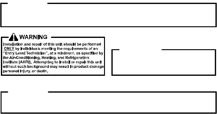
TABLE OF CONTENTS
IMPORTANT INFORMATION |
......................... 2 - 3 |
|
MODEL IDENTIFICATION ............................ |
4 |
- 13 |
AIR HANDLER/COIL IDENTIFICATION ..... 13 |
- 18 |
|
ACCESSORIES ......................................... |
19 |
- 23 |
PRODUCT DESIGN ................................. |
24 |
- 25 |
SYSTEM OPERATION .............................. |
26 - 31 |
TROUBLESHOOTING CHART ......................... |
32 |
SERVICING TABLE OF CONTENTS ................ |
33 |
SERVICING ................................................. |
34 - 65 |
ACCESSORIES WIRING DIAGRAMS ........ |
66 - 74 |
IMPORTANT INFORMATION
Pride and workmanship go into every product to provide our customers with quality products. It is possible, however, that during its lifetime a product may require service. Products should be serviced only by a qualified service technician who is familiar with the safety procedures required in the repair and who is equipped with the proper tools, parts, testing instruments and the appropriate service manual. REVIEW ALL SERVICE INFORMATION IN THE APPROPRIATE
SERVICE MANUAL BEFORE BEGINNING REPAIRS.
IMPORTANT NOTICES FOR CONSUMERS AND SERVICERS
RECOGNIZE SAFETY SYMBOLS, WORDS AND LABELS
 WARNING
This unit should not be connected to, or used in conjunction with, any devices that are not design certified for use with this unit or have not been tested and approved by Goodman. Serious property damage or personal injury, reduced unit performance and/or hazardous conditions may result from the use of devices that have not been approved or certified by Goodman.
 WARNING
To prevent the risk of property damage, personal injury, or death, do not store combustible materials or use gasoline or other flammable liquids or vapors
in the vicinity of this appliance.
 WARNING
Goodman will not be responsible for any injury or property damage arising fromimproper service or service procedures. If you perform service on your own product, you assume responsibility for any personal injury or property damage which may result.
To locate an authorized servicer, please consult your telephone book or the dealer from whom you purchased this product. For further assistance, please contact:
CONSUMER INFORMATION LINE |
CONSUMERINFORMATIONLINE |
GOODMAN® BRAND PRODUCTS |
AMANA® BRAND PRODUCTS |
TOLL FREE 1-877-254-4729 (U.S. only) |
TOLL FREE 1-877-254-4729 (U.S. only) |
email us at: customerservice@goodmanmfg.com |
email us at: customerservice@goodmanmfg.com |
fax us at: (713) 856-1821 |
fax us at: (713) 856-1821 |
(Not a technical assistance line for dealers.) |
(Not a technical assistance line for dealers.) |
Outside the U.S., call 1-713-861-2500.(Not a technical assistance line for dealers.)
Your telephone company will bill you for the call.
2
IMPORTANT INFORMATION
SAFE REFRIGERANT HANDLING
While these items will not cover every conceivable situation, they should serve as a useful guide.
 WARNING
Refrigerants are heavier than air. They can "push out" the oxygen in your lungs or in any enclosed space.To avoid possible difficulty in breathing or death:
• Never purge refrigerant into an enclosed room or space. By law, all refrigerants must be reclaimed.
• If an indoor leak is suspected, thoroughly ventilate the area before beginning work.
• Liquid refrigerant can be very cold. To avoid possible frostbite or blindness, avoid contact with refrigerant and wear gloves and goggles. If liquid refrigerant does contact your skin or eyes, seek medical help immediately.
•Always follow EPA regulations. Never burn refrigerant, as poisonous gas will be produced.
 WARNING
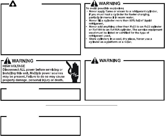
To avoid possible injury, explosion or death, practice safe handling of refrigerants.
To avoid possible explosion, use only returnable (not disposable) service cylinders when removing refrigerant from a system.
•Ensure the cylinder is free of damage which could lead to a leak or explosion.
•Ensure the hydrostatic test date does not exceed 5 years.
•Ensure the pressure rating meets or exceeds 400
lbs.
When in doubt, do not use cylinder.
 WARNING
System contaminants, improper service procedure and/or physical abuse affecting hermetic compressor electrical terminals may cause dangerous system venting.
Thesuccessfuldevelopmentofhermeticallysealedrefrigeration compressors has completely sealed the compressor's moving parts and electric motor inside a common housing, minimizing refrigerant leaks and the hazards sometimes associated with moving belts, pulleys or couplings.
Fundamental to the design of hermetic compressors is a method whereby electrical current is transmitted to the compressor motor through terminal conductors which pass through the compressor housing wall. These terminals are sealed in a dielectric material which insulates them from the housing and maintains the pressure tight integrity of the hermetic compressor. The terminals and their dielectric embedment are strongly constructed, but are vulnerable to careless compressor installation or maintenance procedures and equally vulnerable to internal electrical short circuits caused by excessive system contaminants.
In either of these instances, an electrical short between the terminal and the compressor housing may result in the loss of integrity between the terminal and its dielectric embedment. This loss may cause the terminals to be expelled, thereby venting the vaporous and liquid contents of the compressor housing and system.
A venting compressor terminal normally presents no danger to anyone, providing the terminal protective cover is properly in place.
If, however, the terminal protective cover is not properly in place, a venting terminal may discharge a combination of
(a)hot lubricating oil and refrigerant
(b)flammable mixture (if system is contaminated with air)
in a stream of spray which may be dangerous to anyone in the vicinity. Death or serious bodily injury could occur.
Under no circumstances is a hermetic compressor to be electrically energized and/or operated without having the terminal protective cover properly in place.
See Service Section S-17 for proper servicing.
3
PRODUCT IDENTIFICATION
|
|
Split System Air Conditioners R-22 |
|
Model # |
Description |
|
GSC13018-241AA |
Goodman® Brand Split Condenser 13 Seer condensing units. Initial release. 26" chassis |
|
|
|
|
GSC13036-481AA |
Goodman® Brand Split Condenser 13 Seer condensing units. Initial release. 29" chassis |
|
|
|
|
GSC13036,48*AA |
Goodman® Brand Split Condenser 13 Seer condensing units. |
|
Introduces new 13 SEER AC 3 PH R-22 Goodman Models |
|
|
|
|
|
|
|
|
GSC130**1AB |
Goodman® Brand Split Condenser 13 Seer condensing units. Move location of screw |
|
hole. |
|
|
|
|
|
|
|
|
GSC13036,48*AB |
Goodman® Brand Split Condenser 13 Seer condensing units. Introduces new models |
|
due to the replacement of 8-pole fan motors with 6-pole. |
|
|
|
|
|
|
|
|
GSC13048*AC |
Goodman® Brand Split Condenser 13 Seer condensing units. Move location of screw |
|
hole. |
|
|
|
|
|
|
|
|
GSC13018-30AC |
Goodman® Brand Split Condenser 13 Seer condensing units. Release Models |
|
containing the broad ocean motor 0131M00060 |
|
|
|
|
|
|
|
|
GSC13018,24, 301AD |
|
|
GSC1300421AC, 484AC |
Goodman® Brand Split Condenser 13 Seer condensing units. Remove 1 hairpin from |
|
GSC13018, 24, 301AE |
|
|
GSC130481, 483AE/AF |
coil. |
|
GSC130363AE/AF |
|
|
GSC130361DE/DD |
|
|
GSC13048*AD |
Goodman® Brand Split Condenser 13 Seer condensing units. Release Models contain |
|
the broad ocean motor 0131M00061 |
|
|
|
|
|
|
|
|
GSC130481AG |
Goodman® Brand Split Condenser 13 Seer condensing units. Introduces new models |
|
with Bristol compressors. |
|
|
|
|
|
|
|
|
GSC130181BA |
Goodman® Brand Split Condenser 13 Seer condensing units. Conversion of existing |
|
models using 3/8" diameter tube coils to 5 mm coils. |
|
|
|
|
|
|
|
|
GSC130361BA |
Goodman® Brand Split Condenser 13 Seer condensing units. Initial release. 35" |
|
chassis. |
|
|
|
|
|
|
|
|
GSC130361BA |
Goodman® Brand Split Condenser 13 Seer condensing units. Release Model with |
|
Copeland Scroll Compressor. |
|
|
|
|
|
|
|
|
GSC130361BB |
Goodman® Brand Split Condenser 13 Seer condensing units. Introduces new models |
|
due to the replacement of 8-pole fan motors with 6-pole. |
|
|
|
|
|
|
|
|
GSC130361DF |
Goodman® Brand Split Condenser 13 Seer condensing units. Introduces new models |
|
with Bristol compressors. |
|
|
|
|
|
|
|
|
GSC130181CA |
Goodman® Brand Split Condenser 13 Seer condensing units. Compressor changes |
|
from a recip compressor to a Panasonic Rotary compressor |
|
|
|
|
|
|
|
|
GSC13024-301CA |
Goodman® Brand Split Condenser 13 Seer condensing units. Introduces models with |
|
reduced chassis size from the current 29x32.5 to 26x32 |
|
|
|
|
|
|
|
|
GSC130241DA |
Goodman® Brand Split Condenser 13 Seer condensing units. Release of Goodman 13 |
|
SEER Condensers, with 5 mm coils; compressor change:CR18K7-PFV-230; reduced |
|
|
|
refrigerant charge. |
|
GSC130361FA |
Goodman® Brand Split Condenser 13 Seer condensing units. Converts from 3/8" to |
|
GSC130363BA |
5mm. 2.5 & 3 ton units have new coil slab height and new louver panels. 2.5 - small |
|
GSC130301DA |
chassis; 3 ton medium chassis. |
|
GSC130601CA |
Goodman® Brand Split Condenser 13 Seer condensing units with 5mm, 29" chassis. |
|
GSC130603BA/4BA |
|
4 |
|
|
|
|
PRODUCT IDENTIFICATION
|
Split System Air Conditioners R-22 |
|
Model # |
Description |
|
GSC100903AD |
Goodman® Brand Split Condenser 10 Seer condensing units with new ball |
|
valve/brackets, suction tube/assembly and panel w/offset. |
||
|
||
|
Goodman® Brand Split Condenser 10 Seer condensing units. Initial release of light |
|
GSC100903BA |
commercial models with holding charge only in a double row coil. MODELS DO NOT |
|
GSC101203BA |
CONTAIN REFRIGERANT. Units must be evacuated and charged with R-22 per the |
|
|
installation instructions. |
|
GSC130181BB |
|
|
GSC130241DB |
|
|
GSC130301DB |
Goodman® Brand Split Condenser 13 Seer condensing units. Release models holding |
|
GSC130361FB |
charge only; MODELS DO NOT CONTAIN REFRIGERANT. Units must be evacuated |
|
GSC130421BB |
and charged with R-22 per the installation instructions. |
|
GSC130481BB |
|
|
GSC130601CB |
|
|
|
|
|
GSC130181DA |
Goodman® Brand Split Condenser 13 Seer condensing units. Release models holding |
|
GSC130241EA |
charge only; MODELS DO NOT CONTAIN REFRIGERANT. Units must be evacuated |
|
GSC130301EA |
and charged with R-22 per the installation instructions. Replaces Copeland compressor |
|
GSC130361GA |
with Bristol reciprocating compressor. |
|
|
|
|
GSC130363BB |
Goodman® Brand Split Condenser 13 Seer condensing units. Release models holding |
|
GSC130483BB |
charge only; MODELS DO NOT CONTAIN REFRIGERANT. Units must be evacuated |
|
GSC130603BB |
and charged with R-22 per the installation instructions. |
|
GSC130181FA |
Goodman® Brand Split Condenser 13 Seer condensing units. Release models holding |
|
GSC130241FA |
charge only; MODELS DO NOT CONTAIN REFRIGERANT. Units must be evacuated |
|
|
and charged with R-22 per the installation instructions. Reduction of chassis to 23". |
|
|
|
|
|
Goodman® Brand Split Condenser 13 Seer condensing units. Release models holding |
|
GSC130301EB |
charge only; MODELS DO NOT CONTAIN REFRIGERANT. Units must be evacuated |
|
and charged with R-22 per the installation instructions. Model listed has new 6 pole |
||
|
||
|
motor and corresponding fan blade. |
|
|
|
5

PRODUCT IDENTIFICATION
Split System Air Conditioners R-22
Model # |
Description |
|
|
|
|
GSC140**1AA |
Goodman® Brand Split Condenser 14 Seer condensing units. Introduces Goodman® |
|
Brand 14 Seer AC R-22 models. |
||
|
||
|
|
|
GSC140**1AB |
Goodman® Brand Split Condenser 14 Seer condensing units. New revisions have screw |
|
locations moved in the top panel, base pans, louvers, and control box covers. |
||
|
||
|
|
|
GSC140**1AC |
Goodman® Brand Split Condenser 14 Seer condensing units. Release models |
|
containing the Broad Ocean motor 0131M00060 and 0131M00061 |
||
|
||
|
|
|
GSC140**1AD |
Goodman® Brand Split Condenser 14 Seer condensing units. Revise condenser coils by |
|
removing (1) hairpin. Reducing refrigerant quantities by 6 ounces. |
||
|
||
|
|
|
GSC14018-421BA |
Goodman® Brand Split Condenser 14 Seer condensing units. Conversion of existing |
|
models using 3/8" diameter tube coils to 5 mm coils. |
||
|
||
|
|
|
Split System Air Conditioners R-22 |
|
Model # |
Description |
|
|
|
|
ASC130**1AA |
Amana® Brand Split Condenser 13 Seer condensing units. Initial release new models of |
|
Amana® Brand Deluxe 13 Seer AC R-22 conditioners. |
||
|
||
ASC130**1AB |
Amana® Brand Split Condenser 13 Seer condensing units. Move location of screw hole. |
|
|
|
|
ASC130**1AC |
Amana® Brand Split Condenser 13 Seer condensing units. Introduces horizontal style |
|
louvers. |
||
|
||
ASC1301**1AD |
Amana® Brand Split Condenser 13 Seer condensing units. Remove 1 hairpin from coil. |
|
|
|
|
ASC130601BD |
Special High Feature Split XCondenser 14 Seer condensing units.. Remove 1 |
|
hairpin from coil. Reduce refrigerant quantities by 6 ounces. |
||
|
||
|
|
|
Split System Air Conditioners R-22 |
|
Model # |
Description |
|
|
|
|
VSC13018-601AA |
Value Split Condenser 13 Seer condensing units. Introduces Value 13 Seer AC R-22 |
|
models. 2 year part & 5 year compressor warranty in Bahama Beige. |
||
|
||
|
|
|
VSC130181BA |
Value Split Condenser 13 Seer condensing units. Converts models from 3/8" to 5mm |
|
with new coil slab height & new louver panels. 2 year part & 5 year compressor warranty |
||
VSC13030-361BA |
||
in Bahama Beige. |
||
|
6
PRODUCT IDENTIFICATION
|
Split System Heat Pumps R-22 |
|
Model # |
Description |
|
|
|
|
GSH10***AA |
Goodman® Brand Split Heat Pump 10 Seer heat pump units. Initial release. |
|
|
|
|
GSH10***AB |
Goodman® Brand Split Heat Pump 10 Seer heat pump units. Screw locations |
|
moved in the top panel, base pans, louvers, and control box covers. . |
||
|
||
|
Goodman® Brand Split Heat Pump 10 Seer heat pump units. Initial release of light |
|
GSH100903AC |
commercial models without R-22 refrigerant. MODELS DO NOT CONTAIN |
|
GSH101203AC |
REFRIGERANT. Units must be evacuated and charged with R-22 per the |
|
|
installation instructions. |
|
GSH101203AD |
Goodman® Brand Split Heat Pump 10 Seer heat pump units without R-22 |
|
refrigerant with new ball valve/brackets, suction tube/assembly and panel w/offset. |
||
|
||
|
|
|
GSH13***AA |
Goodman® Brand Split Heat Pump 13 Seer heat pump units. Initial release. |
|
|
|
|
|
Goodman® Brand Split Heat Pump 13 Seer heat pump units. Revision |
|
GSH13**1AB |
introduces the following new models due to the replacement of 8-pole fan motors |
|
with 6-pole and screw locations moved in the top panel, base pans, louvers, and |
||
|
||
|
control box covers. |
|
|
|
|
GSH13**1AC |
Goodman® Brand Split Heat Pump 13 Seer heat pump units. Contain Broad |
|
Ocean motors Screw locations moved in the top panel, base pans, louvers, and |
||
|
control box covers. . |
|
GSH13036-48*AD |
Goodman® Brand Split Heat Pump 13 Seer heat pump units. Introduces models |
|
that contain the broad ocean motor |
||
|
||
GSH13018-301BA |
Goodman® Brand Split Heat Pump 13 Seer heat pump units. Reduction in |
|
chassis size from medium to small. |
||
|
||
GSH130421AE |
Goodman® Brand Split Heat Pump 13 Seer heat pump units. Replaces V10 |
|
reversing valve with V6 reversing valve. |
||
|
||
GSH13048*AG |
Goodman® Brand Split Heat Pump 13 Seer heat pump units. Introduces |
|
model with Bristol Compressors. |
||
|
||
GSH13036*BA/BB |
Goodman® Brand Split Heat Pump 13 Seer heat pump units. Improvements to |
|
increase MOP values on 3 ton units. |
||
|
||
|
|
|
GSH130181BB |
|
|
GSH130241BB |
|
|
GSH130301BB |
Goodman® Brand Split Pump 13 Seer condensing units. Release models holding |
|
GSH130361BC |
charge only; MODELS DO NOT CONTAIN REFRIGERANT. Units must be |
|
GSH 130421AF |
evacuated and charged with R -22 per the installation instructions. |
|
GSH130481AE |
|
|
GSH130601AC |
|
|
GSH130181CA |
Goodman® Brand Split Pump 13 Seer condensing units. Release models holding |
|
GSH130241CA |
charge only; MODELS DO NOT CONTAIN REFRIGERANT. Units must be |
|
GSH130301CA |
evacuated and charged with R -22 per the installation instructions. Changing |
|
GSH130361CA |
reciprocating compressor to scroll compressor. |
|
|
|
|
GSH130(18,24,30,36)1CB |
Goodman® Brand Split Pump 13 Seer condensing units. Release models holding |
|
GSH130421AG |
charge only; MODELS DO NOT CONTAIN REFRIGERANT. Units must be |
|
evacuated and charged with R -22 per the installation instructions. Models listed |
||
GSH130481AF |
||
have new 6 pole motor and corresponding fan blades. |
||
|
||
|
|
|
GSH130363AE |
Goodman® Brand Split Pump 13 Seer condensing units. Release models holding |
|
GSH130483AE |
charge only; MODELS DO NOT CONTAIN REFRIGERANT. Units must be |
|
GSH130603AC |
evacuated and charged with R -22 per the installation instructions. |
7

PRODUCT IDENTIFICATION
Split System Heat Pumps R-22
Model # |
|
Description |
||
GSH140**1AA |
Goodman® Brand Split Heat Pump 14 |
Seer heat pump units. Initial release. |
||
|
|
|
|
|
GSH140**1AB |
Goodman® Brand |
Split Heat Pump 14 |
Seer heat pump units. Screw locations |
|
moved in the top panel, base pans, louvers, and control box covers. |
||||
|
||||
|
|
|
||
GSH140**1AC |
Goodman® Brand Split Heat Pump 14 |
Seer heat pump units. Releases |
||
models with the Broad Ocean motor. |
|
|||
|
|
|||
|
|
|
|
|
GSH140361AF, |
Goodman® Brand |
Split Heat Pump 14 Seer heat pump units. Releases |
||
GSH140421-48AD |
||||
models that replace TXV & compensator with flowrator & accumulator. |
||||
GSH140601AE |
||||
|
|
|
||
|
|
|
|
|
Split System Heat Pumps R-22
Model # |
|
Description |
||
|
|
|
|
|
ASH130**1AA |
Amana® Brand |
Split Heat Pump 13 |
Seer heat pump units. Initial release new |
|
models of Amana® Brand Deluxe 13 Seer R-22 heat pumps. |
||||
|
||||
|
|
|
|
|
ASH130**1AB |
Amana® Brand |
Split Heat Pump 13 |
Seer heat pump units. New revisions have |
|
screw locations moved in the top panel, base pans, louvers, and control box |
||||
|
covers. |
|
|
|
ASH130**1AC |
Amana® Brand |
Split Heat Pump 13 |
Seer heat pump units. New revisions have |
|
horizontal style louvers. |
|
|||
|
|
|||
|
|
|
|
|
Split System Heat Pumps R-22
Model # |
|
Description |
|
|
|
|
|
VSH1318-601AA |
Value Split |
Heat Pump 13 Seer heat pump units. Introduces Value 13 Seer HP R- |
|
22 models. 2 year parts & 5 year compressor warranty in Bahama Beige. |
|||
|
|||
|
|
|
|
8

PRODUCT IDENTIFICATION
|
Single Piece Air Handlers |
|||||
Model # |
|
|
Description |
|||
|
|
|
|
|
|
|
ARUF****16AA |
A Single Piece R Multi-Position PSC Motor Unpainted Flowrater Introduction of new 13 |
|||||
SEER Air Handler Models. All Models will be suitable for use with R-22 and R-410A |
||||||
|
||||||
|
|
|||||
|
A Single Piece R Multi-Position PSC Motor Unpainted Flowrater.Revision replaces the |
|||||
ARUF364216AB |
current spot welded blower housing with the same cinched or crimped design used on |
|||||
|
the 80% furnace line. |
|||||
|
|
|||||
|
A Single Piece R Multi-Position PSC Motor Unpainted Flowrater.Revision replaces the |
|||||
ARUF486016AB |
current spot welded blower housing with the same cinched or crimped design used on |
|||||
|
the 80% furnace line. |
|||||
|
|
|||||
|
A Single Piece R Multi-Position PSC Motor Unpainted Flowrater.Revision replaces the |
|||||
ARUF364216AC |
current spot welded blower housing with the same cinched or crimped design used on |
|||||
|
the 80% furnace line. |
|||||
|
|
|||||
ARUF****16BA |
A Single Piece R Multi-Position PSC Motor Unpainted Flowrater. Revision replaces all |
|||||
|
|
|
|
|
||
ARUFcoils using wavy fin with louver enhanced fin. |
||||||
|
||||||
|
|
|||||
ARUF****1BA |
A Single Piece R Multi-Position PSC Motor Unpainted Flowrater Introducation of R-22 |
|||||
Only Air Handlers. |
||||||
|
||||||
|
|
|||||
ARPF****16AA |
A Single Piece R Multi-Position PSC Motor Painted Flowrater Introducation of new 13 |
|||||
SEER Air Handler Models. All Models will be suitable for use with R-22 and R-410A |
||||||
|
||||||
|
|
|||||
|
A Single Piece R Multi-Position PSC Motor Painted Flowrater. Revision replaces the |
|||||
ARPF364216AB |
current spot welded blower housing with the same cinched or crimped design used on |
|||||
|
the 80% furnace line. |
|||||
|
|
|||||
|
A Single Piece R Multi-Position PSC Motor Painted Flowrater. Revision replaces the |
|||||
ARPF486016AB |
current spot welded blower housing with the same cinched or crimped design used on |
|||||
|
the 80% furnace line. |
|||||
|
|
|||||
ARPF****16BA |
A Single Piece R Multi-Position PSC Motor Painted Flowrater. Revision replaces all |
|||||
ARPFcoils using wavy fin with louver enhanced fin. |
||||||
|
||||||
|
|
|||||
ARPF****1BA |
A Single Piece R Multi-Position PSC Motor Painted Flowrater. Introducation of R-22 |
|||||
Only Air Handlers. |
||||||
|
||||||
|
|
|||||
ADPF****16AA |
A Single Piece Downflow PSC Motor Unpainted Flowrater. Introducation of new 13 |
|||||
SEER Air Handler Models. All Models will be suitable for use with R-22 and R-410A |
||||||
|
||||||
|
|
|||||
|
A Single Piece Downflow PSC Motor Unpainted Flowrater. Revision replaces the current |
|||||
ADPF364216AB |
spot welded blower housing with the same cinched or crimped design used on the 80% |
|||||
|
furnace line. |
|||||
|
|
|||||
|
A Single Piece Downflow PSC Motor Unpainted Flowrater. Revision replaces the current |
|||||
ADPF486016AB |
spot welded blower housing with the same cinched or crimped design used on the 80% |
|||||
|
furnace line. |
|||||
|
|
|||||
|
A Single Piece Downflow PSC Motor Unpainted Flowrater. Revision replaces the current |
|||||
ADPF304216AC |
spot welded blower housing with the same cinched or crimped design used on the 80% |
|||||
|
furnace line. |
|||||
|
|
|||||
ADPF****1BA |
A Single Piece Downflow PSC Motor Unpainted Flowrater Revision replaces all |
|||||
ARPFcoils using wavy fin with louver enhanced fin. |
||||||
|
||||||
|
|
|
|
|
|
|
9

PRODUCT IDENTIFICATION
|
Single Piece Air Handlers |
|
|||
Model # |
Description |
|
|||
|
|
|
|
||
AEPF****16AA |
A Single Piece E Multi-Position Variable-Speed Painted Flowrator. Introducation of |
||||
new 13 SEER Air Handler Models. All Models will be suitable for use with R-22 and |
|||||
|
R-410A |
|
|||
AEPF****16BA |
A Single Piece E Multi-Position Variable-Speed Painted Flowrator. Revision |
||||
introduces new models adding lower kw hit kits on the S&R plate |
|
||||
|
|
||||
|
|
||||
|
A Single Piece E Multi-Position Variable-Speed Painted Flowrator. Revision |
||||
AEPF****16BB |
replaces the current spot welded blower housing with the same cinched or crimped |
||||
|
design used on the 80% furnace line. |
|
|||
AEPF****16CA |
A Single Piece E Multi-Position Variable-Speed Painted Flowrator. Revision |
||||
replaces all ARPFcoils using wavy fin with louver enhanced fin. |
|
||||
|
|
||||
AEPF****1BA |
A Single Piece E Multi-Position Variable-Speed Painted Flowrator Introduction of R- |
||||
22 Only Air Handlers. |
|
||||
|
|
||||
|
|
||||
AEPF313716AA |
A Single Piece E Multi-Position Variable-Speed Painted Flowrator (AEPF) and A |
||||
Single Piece S Multi-Position EEM motor Painted Flowrator (ASPF). Introduction of |
|||||
ASPF313716AA |
|||||
3-Ton Air Handler units with 3-row coil. |
|
||||
|
|
||||
|
|
||||
ASPF****16AA |
A Single Piece S Multi-Position EEM motor Painted Flowrator. Introduces new |
||||
ASPF Air Handlers |
|
||||
|
|
||||
ASPF****16BA |
A Single Piece S Multi-Position EEM motor Painted Flowrator. Revision introuces |
||||
modified ASPF control scheme, to ensure blower operation during and after call for |
|||||
|
heat on units with heat kits and replacing wavy fin with louver enhanced fin on coil |
||||
|
|
|
|||
AWUF****1AA |
A Single Piece Air Handler Wall Mount Unpainted Flowrator. Introduces |
13 SEER |
|||
Dayton wall mount air handlers |
|
||||
|
|
||||
|
A Single Piece Air Handler Wall Mount Unpainted Flowrator. Introduces |
13 SEER |
|||
AWUF****16AA |
Dayton wall mount air handlers. All Models will be suitable for use with R-22 and R- |
||||
|
410A |
|
|||
AWUF3005-101AA |
A Single Piece Air Handler Wall Mount Unpainted Flowrator. Introduces |
13 SEER |
|||
Dayton wall mount air handlers using a Burr Oak Louvered Fin coil. |
|
||||
|
|
||||
AWUF****1BA |
A Single Piece Air Handler Wall Mount Unpainted Flowrator. Revision replaces |
||||
current wavey fin design with new louvered fin design |
|
||||
|
|
||||
AWUF370**16AA |
A Single Piece Air Handler Wall Mount Unpainted Flowrator. Introduction of |
||||
AWUF37 Air Handlers for use with R-22 and R410A. |
|
||||
|
|
||||
|
|
||||
AWUF****16BA |
A Single Piece Air Handler Ceiling Mount N Uncased Flowrater. Revision has |
||||
|
|
|
|
||
louver fins & replaces copper tube hairpins with aluminum hairpins. |
|
||||
|
|
||||
|
|
||||
ACNF****1AA |
A Single Piece Air Handler Ceiling Mount N Uncased Flowrater. Revision release |
||||
all models of 13 SEER Dayton uncased air handlers. |
|
|
|
||
|
|
||||
|
|
||||
ACNF****16AA |
A Single Piece Air Handler Ceiling Mount N Uncased Flowrater. Revision release |
||||
|
|
|
|||
all models of 13 SEER Dayton uncased air handlers.All Models will be suitable for |
|||||
|
use with R-22 and R-410A |
|
|||
ACNF****1AB |
A Single Piece Air Handler Ceiling Mount N Uncased Flowrater. Drain pan material |
||||
change. |
|
|
|
||
|
|
||||
|
|
||||
ACNF****1BA |
A Single Piece Air Handler Ceiling Mount N Uncased Flowrater. Revision replaces |
||||
|
|
|
|
||
current wavey fin design with new louvered fin design |
|
||||
|
|
||||
|
|
||||
AH**-1* |
A Single Piece Air Handler Hydronic Air Handler. Revision replaces the time delay |
||||
relay in the AH air handlers with the UTEC time delay control board. |
|
||||
|
|
||||
10
PRODUCT IDENTIFICATION
|
MBR/MBE Air Handlers |
|||
Model # |
|
|
Description |
|
|
|
|
|
|
MBR****AA-1AA |
Modular Blower R Multi-Position PSC Motor. Introduces module blower with PSC |
|||
blower motor. |
||||
|
||||
|
|
|
|
|
MBE****AA-1AA |
Modular Blower E Multi-Position Variable-Speed. Introduces module blower with |
|||
variable speed blower motor. |
||||
|
||||
|
|
|
|
|
MBE****AA-1BA |
Modular Blower E Multi-Position Variable-Speed.Revision introduces new models |
|||
adding lower kw hit kits on the S&R plate |
||||
|
||||
|
|
|
|
|
|
|
|
|
|
|
|
|
Evaporator Coils |
|
Model # |
|
|
Description |
|
|
|
|
|
|
CAUF*****6AA |
C Indoor Coil A Upflow/Downflow Uncased Flowrator. Introduces 13 SEER CAUF |
|||
|
|
|
||
Dayton Upflow/Downflow coils. |
||||
|
||||
|
|
|||
CAUF*****6BA |
C Indoor Coil A Upflow/Downflow Uncased Flowrator. Revision releases Burr Oak |
|||
|
|
|
||
Louvered Fin in place of the Wavy Fin currently in production. |
||||
|
||||
|
|
|||
CAUF****6*DA |
C Indoor Coil A Upflow/Downflow [Painted or Uncased] Flowrator. Revision |
|||
|
|
|
||
replaces existing copper coils and other associated parts with aluminum |
||||
|
components. |
|||
|
|
|||
CAUF*****6DB |
C Indoor Coil A Upflow/Downflow [Painted or Uncased] Flowrator. Drain pan |
|||
|
|
|
||
material change. |
||||
|
||||
|
|
|||
CAPF*****6AA |
C Indoor Coil A Upflow/Downflow Painted Flowrator. Introduces 13 SEER CAPF |
|||
|
|
|
||
Dayton Upflow/Downflow coils. |
||||
|
||||
|
|
|||
CAPF*****6BA |
C Indoor Coil A Upflow/Downflow Painted Flowrator. Revision releases Burr Oak |
|||
|
|
|
||
Louvered Fin in place of the Wavy Fin currently in production. |
||||
|
||||
|
|
|||
CAPF/CAUF36***CA |
C Indoor Coil A Upflow/Downflow [Painted or Uncased] Flowrator. Revision |
|||
|
|
|
||
redesigns for performance improvement from 2 row to 3 row. |
||||
|
||||
|
|
|||
CHPF*****6AA |
C Indoor Coil Horizontal A Coil Painted Flowrator. Release 13 SEER CHPF |
|||
horizontal A coil. |
||||
|
||||
|
|
|||
|
C Indoor Coil A Upflow/Downflow [Painted or Uncased] Flowrator. Revision |
|||
|
|
|
|
|
CAPF*****6DA |
replaces existing copper coils and other associated parts with aluminum |
|||
|
components. |
|||
CAPF*****6DB |
C Indoor Coil A Upflow/Downflow [Painted or Uncased] Flowrator. Drain pan |
|||
|
|
|
||
material change. |
||||
|
||||
|
|
|||
|
C Indoor Coil Horizontal A Coil Painted Flowrator. Release 13 SEER CHPF |
|||
CHPF*****6BA |
horizontal A coil. Revision releases Burr Oak Louvered Fin in place of the Wavy |
|||
Fin currently in production. The rows change by one, (i.e. 4 row to 3 row; 3 row to |
||||
|
||||
|
2 row) where applicable. |
|||
|
|
|
|
|
11

PRODUCT IDENTIFICATION
|
Evap orator Co ils |
|
|
|
|
Model # |
D escription |
|
CHPF1824A6CA |
|
|
CHPF2430B6CA |
|
|
CHPF3636B6CA |
C Indoor Coil Horizontal A Coil Painted Flowrator. 13 SEER CH PF horizontal A |
|
CH PF3642C 6CA |
||
coil, revision has louver fins & replaces copper tube hairpins with alum inum |
||
CH PF3642D 6CA |
||
hairpins. |
||
CHPF3743C6BA |
||
|
||
CHPF3743D6BA |
|
|
CH PF4860D 6DA |
|
|
CHPF1824A6CB |
|
|
CHPF2430B6CB |
|
|
CHPF3636B6CB |
C Indoor Coil Horizontal A Coil Painted Flowrator. 13 SEER CH PF horizontal A |
|
CH PF3642C 6CB |
||
CH PF3642D 6CB |
coil. D rain pan m aterial change. |
|
CHPF3743C6BB |
|
|
CHPF3743D6BB |
|
|
CH PF4860D 6DB |
|
|
CSCF*****6AA |
C Indoor Coil S Horizontal Slab Coil C Upainted Flowrator. Release 13 SEER |
|
CSCF slab horizontal coil. |
||
|
||
|
C Indoor Coil S Horizontal Slab Coil C Upainted Flowrator. Revision releases Burr |
|
CSCF*****6BA |
Oak Louvered Fin in place of the W avy Fin currently in production. The rows |
|
|
change by one, (i.e. 4 row to 3 row; 3 row to 2 row) where applicable. |
|
|
|
|
CSCF1824N6BB |
|
|
CSCF3036N6BB |
C Indoor Coil S Horizontal Slab Coil C Upainted Flowrator. Drain pan m aterial |
|
CSCF3642N 6CB |
change. |
|
CSCF4860N 6CB |
|
|
CTPF*****6AA |
C Indoor Coil T Coated Painted Flowrator. Initial release of coated coils. |
|
CTPF1824*6AB |
|
|
CTPF3030*6AB |
|
|
CTPF3131*6AB |
C Indoor Coil T Coated Painted Flowrator. Drain pan m aterial change. |
|
CTPF3636*6AC |
||
|
||
CTPF3642*6AB |
|
|
CTPF4860*6AB |
|
|
CTUF1824*6AA |
|
|
CTUF3030*6AA |
|
|
CTUF3131*6AA |
C Indoor Coil T Coated Unpainted Flowrator. Initial release. |
|
CTUF3636*6AA |
||
|
||
CTUF3642*6AA |
|
|
CTUF4860*6AA |
|
|
CTUF1824*6AB |
|
|
CTUF3030*6AB |
|
|
CTUF3131*6AB |
C Indoor Coil T Coated Unpainted Flowrator. Drain pan material change. |
|
CTUF3636*6AC |
||
|
||
CTUF3642*6AB |
|
|
CTUF4860*6AB |
|
|
CKF24-2PA |
|
|
CKF36-2PA |
C Indoor Coil K Air Conditioner Flowrator. |
|
CKF36-5PA |
|
|
CPKF36-2PA |
|
|
CPKF36-5PA |
C Indoor Coil P Heat Pum p K Air C onditioner Flowrator. |
|
CPKF48-5PA |
|
|
|
|
|
CKL36-1PA |
|
|
CKL49-1PA |
C Indoor Coil K L |
|
CKL60-1PA |
||
|
||
CKL60-3PA |
|
12

PRODUCT IDENTIFICATION |
|
|
|
|
|
||
G |
S |
C |
14 |
036 |
1 |
A |
A |
BRAND: |
|
|
|
|
|
|
|
|
|
|
|
|
|
|
MINOR |
|||
G: Goodman® Brand / |
|
|
|
|
|
|
|
|
|
|
|
REVISION: |
||||||
Amana® Brand Distinctions |
|
|
|
|
|
|
|
|
|
|
|
A: Initial Release |
||||||
|
SEER: |
|
|
|
||||||||||||||
A: Amana® Brand |
|
|
10: 10 SEER |
|
|
|
|
|
|
|
|
|||||||
|
|
|
|
|
|
|
|
|
|
|
|
|||||||
V: Value |
|
|
13: 13 SEER |
|
|
|
|
|
|
|
|
|||||||
|
|
|
|
|
|
|
14: 14 SEER |
|
|
|
|
|
MAJOR |
|
||||
|
|
|
|
|
|
|
|
|
||||||||||
|
|
|
|
|
|
|
|
|
|
|
|
|
|
|
|
REVISION: |
|
|
|
|
|
|
|
|
|
|
|
|
|
|
|
|
|
|
A: Initial Release |
|
|
|
|
|
|
|
|
|
|
|
|
|
|
|
|
|
|
|
||
|
|
|
|
|
|
|
|
|
|
|
|
|
|
|
|
|
|
|
|
|
|
|
|
|
|
|
|
|
NOMINAL |
|
|
|
|
||||
|
|
|
|
|
|
|
|
|
|
CAPACITY: |
|
|
|
|
||||
|
PRODUCT |
|
|
|
|
|
018: 1.5 Tons |
|
|
|
|
|||||||
|
CATEGORY: |
|
|
|
|
|
024: 2 Tons |
|
|
|
|
|||||||
|
S: Split System |
|
|
|
|
|
030: 2.5 Tons |
|
|
|
|
|||||||
|
|
|
|
|
|
|
|
|
|
036: 3 Tons |
|
|
|
|
||||
|
|
|
|
|
|
|
|
|
|
|||||||||
|
|
|
|
|
|
|
|
|
|
042: 3.5 Tons |
|
|
|
|
||||
|
|
|
|
|
|
|
|
|
|
048: 4 Tons |
|
|
|
|
||||
|
|
|
|
UNIT TYPE: |
|
|
|
|||||||||||
|
|
|
|
C: Condenser R-22 |
|
|
060: 5 Tons |
|
|
|
|
|||||||
|
|
|
|
H: Heat Pump R-22 |
|
|
|
|
|
|
|
|
|
|
|
|||
|
|
|
|
|
|
|
|
|
|
|
|
|
|
|
|
|
|
|
|
|
|
|
|
|
|
|
|
|
|
|
|
ELECTRICAL: |
|
|
|||
|
|
|
|
|
|
|
|
|
|
|
1: |
208-230V/1ph/60Hz |
|
|||||
|
|
|
|
|
|
|
|
|
|
|
3: |
208-230v/3ph/60Hz |
|
|||||
|
|
|
|
|
|
|
|
|
|
|
4: |
460v/3ph/60Hz |
|
|||||
|
|
|
|
|
|
|
|
|
|
|
|
|
|
|
|
|
|
|
|
|
|
|
|
|
|
|
|
|
|
|
|
|
|
|
|
|
|
C |
PKF |
036 |
2 |
A |
|
|
|
|
|
|
|
|
|
|
REVISION: |
|
PRODUCT CATEGORY: |
|
|
|
|
|
|
|
A: Revision |
|||
|
C: Split System |
|
|
|
|
|
|
|
|
|
|
|
|
|
|
|
|
|
|
|
|
||
|
|
|
|
|
|
|
|
|
|
|
|
|
|
|
|
|
|
|
|
ELECTRICAL: |
|
||
|
UNIT TYPE: |
|
|
|
1: |
208-230V/1ph/60Hz |
|
||||
|
E: Commercial Air Conditioner |
|
|
2: |
220-240V/1ph/50 Hz |
|
|||||
|
K: Air Conditioner |
|
|
|
3: |
208-230v/3ph/60Hz |
|
||||
|
P: Heat Pump |
|
|
|
4: 308/415V/3ph/50Hz |
|
|||||
|
|
|
|
|
|
|
|
|
|||
|
|
|
|
NOMINAL CAPACITY: |
|
|
|
|
|||
|
|
|
018: 1.5 Tons |
048: |
4 |
Tons |
|
||||
|
024: |
2 Tons |
060: |
5 |
Tons |
|
|||||
|
|
|
030: 2.5 Tons |
070: |
5 |
Tons |
|
||||
|
036: |
3 Tons |
090: 7.5 |
Tons |
|
||||||
|
|
|
042: 3.5 Tons |
120: |
10 Tons |
|
|||||
|
|
|
|
|
|
|
|
|
|
|
|
13

PRODUCT IDENTIFICATION |
|
|
|
|
C |
KL |
036 |
2 |
A |
|
|
|
|
|
|
|
|
|
|
|
REVISION: |
|
PRODUCT CATEGORY: |
|
|
|
|
|
|
|
|
A: Revision |
|||
|
C: Split System |
|
|
|
|
|
|
|
|
|
|
|
|
|
|
|
|
|
|
|
|
|
|
||
|
|
|
|
|
|
|
|
|
|
|
|
|
|
|
|
|
|
|
|
|
ELECTRICAL: |
|
|||
|
UNIT TYPE: |
|
|
|
1: |
208-230V/1ph/60Hz |
|
|||||
|
E: Commercial Air Conditioner |
|
|
2: |
220-240V/1ph/50 Hz |
|
||||||
|
K: Air Conditioner |
|
|
|
3: |
208-230v/3ph/60Hz |
|
|||||
|
P: Heat Pump |
|
|
|
4: 308/415V/3ph/50Hz |
|
||||||
|
|
|
|
|
|
|
|
|
|
|||
|
|
|
|
NOMINAL CAPACITY: |
|
|
|
|
|
|||
|
|
|
018: 1.5 Tons |
048: |
4 |
Tons |
|
|||||
|
|
024: |
2 Tons |
060: |
5 |
Tons |
|
|||||
|
|
|
030: 2.5 Tons |
070: |
5 |
Tons |
|
|||||
|
|
036: |
3 Tons |
090: 7.5 |
Tons |
|
||||||
|
|
|
042: 3.5 Tons |
120: |
10 Tons |
|
||||||
|
|
|
|
|
|
|
|
|
|
|
|
|
|
|
|
|
|
|
|
|
|
|
|
|
|
C |
KF |
036 |
2 |
A |
|
|
|
|
|
|
|
|
|
REVISION: |
|
PRODUCT CATEGORY: |
|
|
|
|
|
|
|
A: Revision |
||
|
C: Split System |
|
|
|
|
|
|
|
|
|
|
|
|
|
|
|
|
|
|
|
|
|
|
|
|
|
|
|
|
|
|
|
|
|
|
|
|
|
|
ELECTRICAL: |
|
||
|
UNIT TYPE: |
|
|
|
1: |
208-230V/1ph/60Hz |
|
|||
|
E: Commercial Air Conditioner |
|
|
2: |
220-240V/1ph/50 Hz |
|
||||
|
K: Air Conditioner |
|
|
|
3: |
208-230v/3ph/60Hz |
|
|||
|
P: Heat Pump |
|
|
|
4: 308/415V/3ph/50Hz |
|
||||
|
|
|
|
|
|
|
|
|||
|
|
|
NOMINAL CAPACITY: |
|
|
|
|
|||
|
|
018: 1.5 Tons |
048: |
4 |
Tons |
|
||||
|
024: |
2 Tons |
060: |
5 |
Tons |
|
||||
|
|
030: 2.5 Tons |
070: |
5 |
Tons |
|
||||
|
036: |
3 Tons |
090: 7.5 |
Tons |
|
|||||
|
|
042: 3.5 Tons |
120: |
10 Tons |
|
|||||
|
|
|
|
|
|
|
|
|
|
|
14
PRODUCT IDENTIFICATION
C |
E |
120 |
5 |
A |
|
|
|
|
|
|
|
|
|
|
REVISION: |
|
PRODUCT CATEGORY: |
|
|
|
|
|
|
|
|
A: Revision |
||
|
C: Split System |
|
|
|
|
|
|
|
|
|
|
|
|
|
|
|
|
|
|
|
|
|
|
|
|
|
|
|
|
|
|
|
|
||
|
|
|
|
|
|
|
ELECTRICAL: |
|
|||
|
UNIT TYPE: |
|
|
|
1: 208-230V/1ph/60Hz |
|
|||||
|
E: Commercial Air Conditioner |
|
|
2: |
220-240V/1ph/50 Hz |
|
|||||
|
K: Air Cojditioner |
|
|
|
3: |
208-230v/3ph/60Hz |
|
||||
|
P: Heat Pump |
|
|
|
4: 308/415V/3ph/50Hz |
|
|||||
|
|
|
|
|
|
|
|
||||
|
|
|
NOMINAL CAPACITY: |
|
|
|
|
||||
|
|
018: 1.5 Tons |
048: |
4 |
Tons |
|
|||||
|
024: |
2 Tons |
060: |
5 |
Tons |
|
|||||
|
|
030: 2.5 Tons |
070: |
5 |
Tons |
|
|||||
|
036: |
3 Tons |
090: 7.5 Tons |
|
|||||||
|
|
042: 3.5 Tons |
120: |
10 |
Tons |
|
|||||
|
|
|
|
|
|
|
|
|
|
|
|
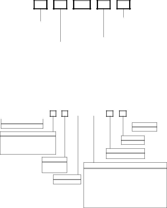
THIS NOMENCLATURE IS TO BE USED TRHOUGH JULY 2006
|
A |
R U |
F |
||
|
|
|
|
|
|
Product Type
A: Single Piece Air Handler
Application
C:Ceiling Mount PSC Motor
D:Downflow PSC Motor
E:Multi-Position Variable Speed Motor
R:Multi-Position PSC Motor
W:Wall Mount PSC Motor
Cabinet Finish
U: Unpainted
P: Painted
N: Uncased
Expansion Device
F: Flowrater
3642 |
1 |
A |
A |
|
|
|
|
|
|
Minor Revision
A: Initial Release
Major Revision
A: Initial Release
Electrical
1: 208/230V, 1 Phase, 60 Hz
Nominal Capacity Range @ 13 SEER
Multi-Position & Downflow Applications
3642: 3 - 3 1/2 tons 1830: 1 1/2 - 3 1/2 tons
1729: 1 1/2 - 2 1/2 Tons 10 SEER (for export systems)
Ceiling Mount & Wall Mount Applications
1805: Nominal Cooling Capacity
Electric Heat kw - 1 1/2 tons Cooling/5 kw Electric Heat 2405: Nominal Cooling Capacity
Electric Heat kw - 2 Tons Cooling/5 kw Electric Heat 3608: Nominal Cooling Capacity
Electric Heat kw - 3 Tons Cooling/8 kw Electric Heat
15

PRODUCT IDENTIFICATION
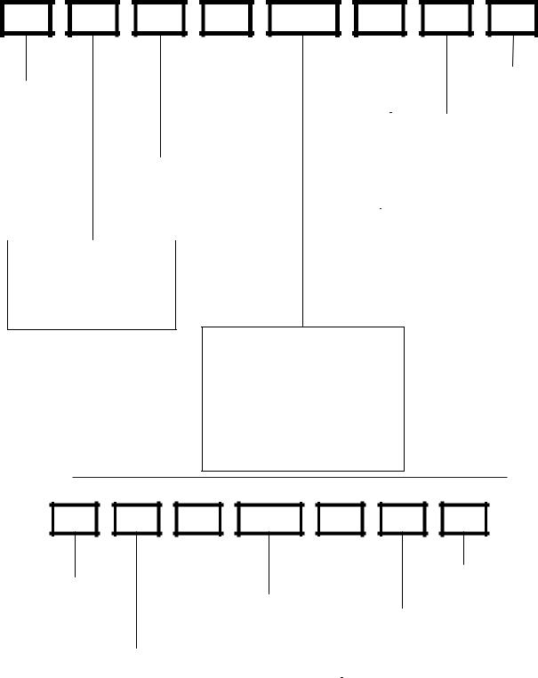
THIS NOMENCLATURE IS TO BE USED AFTER JULY 2006
A |
W |
U |
F |
3642 |
1 |
6 |
A |
A |
|
|
|
|
|
EXPANSION |
|
|
|
|
|
|
|
|
||
|
|
|
|
|
|
|
|
|
|
MINOR |
|||||
|
PRODUCT |
|
|
|
DEVICE: |
|
|
|
|
|
|||||
|
|
|
|
|
|
|
|
|
REVISION* |
||||||
|
TYPE: |
|
|
|
F: Flowrater |
|
|
|
|
|
|||||
|
|
|
|
|
|
|
|
|
|
|
|
||||
|
|
|
|
|
|
|
|
|
|
|
|
||||
|
A: Air Handler |
|
|
|
T: TXV |
|
|
|
|
|
|
|
|
||
|
|
|
|
|
(Expansion |
|
|
|
|
|
|
|
|
||
|
|
|
|
|
|
|
|
|
|
|
|
|
|||
|
|
|
|
|
Device) |
|
|
|
|
MAJOR |
|
|
|||
|
|
|
|
|
|
|
|
|
|
|
|
REVISION* |
|
|
|
|
|
|
CABINET FINISH: |
|
|
|
|
|
|
|
|
|
|||
|
|
|
U: Unpainted |
|
|
|
|
|
|
|
|
|
|||
|
|
|
P: Painted |
|
|
|
|
|
REFRIGERANT CHARGE: |
|
|||||
|
|
|
N: Uncased |
|
|
|
No Digit: R-22 Only |
|
|||||||
|
|
|
|
|
|
|
|
|
6: |
|
R-410A or R-22 |
|
|||
|
|
|
|
|
|
|
|
|
|
|
|
|
|
|
|
|
APPLICATION |
|
|
|
|
|
|
|
|
|
|
|
|||
|
|
|
|
|
ELECTRICAL: |
|
|
|
|
|
|||||
C: Ceiling Mount PSC Motor |
|
|
|
|
|
|
|
|
|
||||||
|
|
|
|
1: 208-230V/1ph/60Hz |
|
|
|
|
|
||||||
D: Downflow PSC Motor |
|
|
|
|
|
|
|
|
|
||||||
|
|
|
|
|
|
|
|
|
|
|
|||||
E: Multi-Position Varible Speed Motor |
|
|
|
|
|
|
|
|
|||||||
S:Energy-Efficient Motor
R:Multi-Position PSC Motor
T:Coated Coils
W: Wall Mount PSC Motor
NOMINAL CAPACITY RANGE:
@ 13 SEER
Dedicated Application
3636: 3 Tons
Multi-Position & Downflow Applications 3137: 3 Tons
3642: 3 - 3 1/2 Tons 1830: 1 1/2 - 3 1/2 Tons @10 SEER
1729: 1 1/2 - 2 1/2 Tons (for export systems)
Ceiling Mount & Wall Mount Applications (Nominal Cooling Capacity/Electric Heat kW) 1803: 1 1/2 Tons Cooling / 3 kW Electric Heat 1805: 1 1/2 Tons Cooling / 5 kW Electric Heat 2405: 2 Tons Cooling / 5 kW Electric Heat 3608: 3 Tons Cooling / 8 kW Electric Heat 3105: 1.5 - 2.5 Tons Cooling / 5kW Electric Heat 3210: 2 - 2.5 Tons Cooling / 10kW Electric Heat 3705: 3 Tons Cooling / 5 kW Electric Heat 3708: 3 Tons Cooling / 8 kW Electric Heat 3710: 3 Tons Cooling / 10 kW Electric Heat
All Airhandlers use DIRECT DRIVE MOTORS. Power supply is AC 208-230v, 60 hz, 1 phase.
16
PRODUCT IDENTIFICATION |
|
|
|
|
|||
C |
A |
P |
F |
1824 |
A |
6 |
A |
|
|
|
|
EXPANSION |
|
|
|
|
|
|
|
|
|
|
|
|
|
|
REVISION |
|
|||
PRODUCT |
|
|
DEVICE: |
|
|
|
A: Revision |
|
|||
TYPE: |
|
|
F: Flowrater |
|
|
|
|
|
|
||
|
|
|
|
|
|
|
|
||||
C: Indoor Coil |
|
|
|
|
|
|
REFRIGERANT |
|
|||
|
|
|
|
|
|
|
|
CHARGE: |
|
||
|
|
|
|
|
|
|
|
6: R-410A or R-22 |
|
||
|
|
|
CABINET FINISH: |
|
|
|
2: R-22 |
|
|||
|
|
|
U: Unpainted |
|
|
|
4: R-410a |
|
|||
|
|
|
P: Painted |
|
|
|
|
|
|
|
|
|
|
|
|
|
|
|
|
|
|
|
|
|
|
|
N: Unpainted Case |
|
|
|
|
|
|||
|
|
|
|
|
NOMINAL WIDTH FOR GAS FURNACE |
||||||
|
|
|
|
|
|
|
A: Fits 14" Furnace Cabinet |
||||
|
APPLICATION |
|
|
|
B: Fits 17 1/2" Furnace Cabinet |
||||||
|
A: Upflow/Downflow Coil |
|
|
|
C: Fits 21" Furnace Cabinet |
||||||
|
H: Horizontal A Coil |
|
|
|
D: Fits 24 1/2" Furnace Cabinet |
||||||
|
S: Horizontal Slab Coil |
|
|
|
N: Does Not Apply (Horizontal Slab Coils) |
||||||
|
T: Coated Coil |
|
|
|
|
|
|
|
|
||
|
|
|
|
|
|
|
|
||||
NOMINAL CAPACITY RANGE @ 13 SEER
1824: 1 1/2 to 2 Tons 3030: 2 1/2 Tons 3636: 3 Tons
3642: 3 to 3 1/2 Tons 3743: 3 to 3 1/2 Tons 4860: 4 & 5 Tons 4961: 4 & 5 Tons
MB |
R |
8 |
00 |
A |
A |
1 |
|
|
|
|
|
|
|
|
|
|
|
|
ELECTRICAL SUPPLY: |
|
||
DESIGN SERIES: |
|
|
|
|
|
|
|
|
|
|
1: 208-230V/60hZ/1 ph |
|
|||
MB: Modular Blower |
|
|
|
FACTORY HEAT |
|
|
|
|
|
|
|
|
|||
|
|
|
|
|
00: No Heat |
|
DESIGN SERIES |
|
|
|
|||||
|
|
|
|
|
|
|
|||||||||
|
|
|
|
|
|
|
|
|
A: First Series |
|
|
|
|
||
|
|
|
|
|
|
|
|
|
|
|
|
||||
|
|
|
|
|
|
|
|
|
|
|
|
|
|
|
|
|
|
|
|
|
|
|
|
|
|
|
|
|
|
|
|
|
MOTOR TYPE: |
|
|
|
|
|
|
|
|
|
|
|
|
|
|
|
R: Constant Speed |
|
|
|
|
|
|
|
|
|
|
|
|
|
|
|
E: Variable Speed |
|
|
|
|
CIRCUIT BREAKER |
|
|
MODEL |
MFG.# |
|||||
|
|
|
|
|
|
|
A: No Circuit Breaker |
|
|
||||||
|
|
|
|
|
|
|
|
|
|||||||
|
|
|
|
|
|
|
|
MBR0800 |
MBR0800 |
||||||
|
|
|
|
|
|
|
B: Circuit Breaker |
|
|
||||||
|
|
|
|
|
|
|
|
MBR1200 |
MBR1200 |
||||||
|
|
AIRFLOW DELIVERED |
|
|
|
|
|
|
|||||||
|
|
|
|
|
|
|
|
MBR1600 |
MBR1600 |
||||||
|
|
08: 800 CFM |
|
|
|
|
|
|
|
||||||
|
|
|
|
|
|
|
|
|
MBR2000 |
MBR2000 |
|||||
|
|
12: 1200 CFM |
|
|
|
|
|
|
|||||||
|
|
|
|
|
|
|
|
MBE1200 |
MBE1200 |
||||||
|
|
16: 1600 CFM |
|
|
|
|
|
|
|||||||
|
|
|
|
|
|
|
|
MBE1600 |
MBE1600 |
||||||
|
|
20: 2000 CFM |
|
|
|
|
|
|
|||||||
|
|
|
|
|
|
|
|
MBE2000 |
MBE2000 |
||||||
|
|
|
|
|
|
|
|
|
|
|
|
||||
17
ACCESSORIES
Model |
|
Description |
ASC13018 |
ASC13024 |
ASC13030 |
ASC13036 |
ASC13042 |
ASC13048 |
ASC13060 |
OT18-60A |
|
Outdoor Thermostat |
--- |
--- |
--- |
--- |
--- |
--- |
--- |
FSK01A* |
|
Freeze Protection Kit |
X |
X |
X |
X |
X |
X |
X |
ASC01 |
|
Anti Short Cycle Kit |
X |
X |
X |
X |
X |
X |
X |
TX2N2* |
|
TXV Kit |
X |
--- |
--- |
--- |
--- |
--- |
--- |
TX3N2* |
|
TXV Kit |
x |
x |
x |
x |
--- |
--- |
--- |
TX5N2* |
|
TXV Kit |
--- |
--- |
--- |
--- |
X |
X |
X |
CSR-U-1 |
|
Hard Start Kit |
X |
X |
X |
X |
--- |
--- |
--- |
CSR-U-2 |
|
Hard Start Kit |
--- |
--- |
--- |
X |
X |
X |
X |
CSR-U-3 |
|
Hard Start Kit |
--- |
--- |
--- |
--- |
--- |
X |
X |
|
|
|
|
|
|
|
|
|
|
Model |
|
Description |
G/VSC13018 |
G/VSC13024 |
G/VSC13030 |
G/VSC13036 |
|
|
|
OT18-60A |
|
Outdoor Thermostat |
--- |
--- |
--- |
--- |
|
|
|
FSK01A* |
|
Freeze Protection Kit |
X |
X |
X |
X |
|
|
|
ASC01 |
|
Anti Short Cycle Kit |
X |
X |
X |
X |
|
|
|
TX2N2* |
|
TXV Kit |
X |
--- |
--- |
--- |
|
|
|
TX3N2* |
|
TXV Kit |
x |
x |
x |
x |
|
|
|
TX5N2* |
|
TXV Kit |
--- |
--- |
--- |
--- |
|
|
|
CSR-U-1 |
|
Hard Start Kit |
X |
X |
X |
X |
|
|
|
CSR-U-2 |
|
Hard Start Kit |
--- |
--- |
--- |
X |
|
|
|
CSR-U-3 |
|
Hard Start Kit |
--- |
--- |
--- |
--- |
|
|
|
|
|
|
|
|
|
|
|
|
|
Model |
|
Description |
G/VSC13042 |
G/VSC13048 |
G/VSC13060 |
|
|
|
|
OT18-60A |
|
Outdoor Thermostat |
--- |
--- |
--- |
|
|
|
|
FSK01A* |
|
Freeze Protection Kit |
X |
X |
X |
|
|
|
|
ASC01 |
|
Anti Short Cycle Kit |
X |
X |
X |
|
|
|
|
TX2N2* |
|
TXV Kit |
--- |
--- |
--- |
|
|
|
|
TX3N2* |
|
TXV Kit |
--- |
--- |
--- |
|
|
|
|
TX5N2* |
|
TXV Kit |
X |
X |
X |
|
|
|
|
CSR-U-1 |
|
Hard Start Kit |
--- |
--- |
--- |
|
|
|
|
CSR-U-2 |
|
Hard Start Kit |
X |
X |
X |
|
|
|
|
CSR-U-3 |
|
Hard Start Kit |
--- |
X |
X |
|
|
|
|
|
|
|
|
|
|
|
|
|
|
Model |
|
Description |
GSC100903 |
GSC100904 |
GSC101203 |
GSC101204 |
|
|
|
FSK01A* |
|
Freeze Protection Kit |
x |
x |
x |
x |
|
|
|
ASC01 |
|
Anti Short Cycle Kit |
x |
x |
x |
x |
|
|
|
OT/EHR18-60 |
|
Emergency Heat relay kit |
--- |
--- |
--- |
--- |
|
|
|
*Installed on |
indoor coil. |
|
|
|
|
|
|
|
|
18
ACCESSORIES
Model |
|
Description |
G/VSH13018 |
G/VSH13024 |
G/VSH13030 |
G/VSH13036 |
G/VSH13042 |
G/VSH13048 |
G/VSH13060 |
AFE18-60A |
|
All Fuel Kit |
X |
X |
X |
X |
X |
X |
X |
OT18-60A |
|
Outdoor Thermostat |
X |
X |
X |
X |
X |
X |
X |
FSK01A* |
|
Freeze Protection Kit |
X |
X |
X |
X |
X |
X |
X |
ASC01 |
|
Anti Short Cycle Kit |
X |
X |
X |
X |
X |
X |
X |
TX2N2* |
|
TXV Kit |
x |
--- |
--- |
--- |
--- |
--- |
--- |
TX3N2* |
|
TXV Kit |
x |
X |
X |
X |
--- |
--- |
--- |
TX5N2* |
|
TXV Kit |
--- |
--- |
--- |
--- |
X |
X |
X |
OT18-60A |
|
Outdoor Lockout Stat |
X |
X |
X |
X |
X |
X |
X |
OT/EHR18-60 |
|
Emergency Heat relay kit |
X |
X |
X |
X |
X |
X |
X |
CSR-U-1 |
|
Hard Start Kit |
X |
X |
X |
X |
--- |
--- |
--- |
CSR-U-2 |
|
Hard Start Kit |
--- |
--- |
--- |
X |
X |
X |
X |
CSR-U-3 |
|
Hard Start Kit |
--- |
--- |
--- |
--- |
--- |
X |
X |
|
|
|
|
|
|
|
|
|
|
Model |
|
Description |
ASH13018 |
ASH13024 |
ASH13030 |
ASH13036 |
ASH13042 |
ASH13048 |
ASH13060 |
AFE18-60A |
|
All Fuel Kit |
X |
X |
X |
X |
X |
X |
X |
OT18-60A |
|
Outdoor Thermostat |
X |
X |
X |
X |
X |
X |
X |
FSK01A* |
|
Freeze Protection Kit |
X |
X |
X |
X |
X |
X |
X |
ASC01 |
|
Anti Short Cycle Kit |
X |
X |
X |
X |
X |
X |
X |
TX2N2* |
|
TXV Kit |
x |
--- |
--- |
--- |
--- |
--- |
--- |
TX3N2* |
|
TXV Kit |
x |
X |
X |
X |
--- |
--- |
--- |
TX5N2* |
|
TXV Kit |
--- |
--- |
--- |
--- |
X |
X |
X |
OT18-60A |
|
Outdoor Lockout Stat |
X |
X |
X |
X |
X |
X |
X |
OT/EHR18-60 |
|
Emergency Heat relay kit |
X |
X |
X |
X |
X |
X |
X |
CSR-U-1 |
|
Hard Start Kit |
X |
X |
X |
X |
--- |
--- |
--- |
CSR-U-2 |
|
Hard Start Kit |
--- |
--- |
--- |
X |
X |
X |
X |
CSR-U-3 |
|
Hard Start Kit |
--- |
--- |
--- |
--- |
--- |
X |
X |
|
|
|
|
|
|
|
|
|
|
Model |
|
Description |
GSH100903 |
GSH100904 |
GSH101203 |
GSH101204 |
|
|
|
FSK01A* |
|
Freeze Protection Kit |
x |
x |
x |
x |
|
|
|
ASC01 |
|
Anti Short Cycle Kit |
x |
x |
x |
x |
|
|
|
OT/EHR18-60 |
|
Emergency Heat relay kit |
--- |
--- |
--- |
--- |
|
|
|
*Installed on |
indoor coil. |
|
|
|
|
|
|
|
|
19
ACCESSORIES
Model |
Description |
CPKF24 |
CPKF36 |
CPKF42 |
CPKF48 |
CPKF60 |
CPKF61 |
|
AFE18-60A |
All Fuel Kit |
x |
x |
x |
x |
x |
x |
|
OT18-60A |
Outdoor Thermostat |
x |
x |
x |
x |
x |
x |
|
FSK01A* |
Freeze Protection Kit |
x |
x |
x |
x |
x |
x |
|
ASC01 |
Anti Short Cycle Kit |
x |
x |
x |
x |
x |
x |
|
TX2N2* |
TXV Kit |
--- |
--- |
--- |
--- |
--- |
--- |
|
TX3N2* |
TXV Kit |
x |
x |
--- |
--- |
--- |
--- |
|
TX5N2* |
TXV Kit |
--- |
--- |
x |
x |
x |
x |
|
OT18-60A |
Outdoor Lockout Stat |
x |
x |
x |
x |
x |
x |
|
OT/EHR18-60 |
Emergency Heat relay kit |
x |
x |
x |
x |
x |
x |
|
CSR-U-1 |
Hard Start Kit |
x |
x |
--- |
--- |
--- |
--- |
|
CSR-U-2 |
Hard Start Kit |
--- |
x |
x |
x |
x |
x |
|
CSR-U-3 |
Hard Start Kit |
--- |
--- |
--- |
x |
x |
x |
|
|
|
|
|
|
|
|
|
|
Model |
Description |
CKF24 |
CKF36 |
CKF48 |
CKF60 |
CKF70 |
|
|
AFE18-60A |
All Fuel Kit |
--- |
--- |
--- |
--- |
--- |
|
|
OT18-60A |
Outdoor Thermostat |
--- |
--- |
--- |
--- |
--- |
|
|
FSK01A* |
Freeze Protection Kit |
x |
x |
x |
x |
x |
|
|
ASC01 |
Anti Short Cycle Kit |
x |
x |
x |
x |
x |
|
|
TX2N2* |
TXV Kit |
--- |
--- |
--- |
--- |
--- |
|
|
TX3N2* |
TXV Kit |
x |
x |
--- |
--- |
--- |
|
|
TX5N2* |
TXV Kit |
--- |
--- |
x |
x |
--- |
|
|
OT18-60A |
Outdoor Lockout Stat |
--- |
--- |
--- |
--- |
--- |
|
|
OT/EHR18-60 |
Emergency Heat relay kit |
--- |
--- |
--- |
--- |
--- |
|
|
CSR-U-1 |
Hard Start Kit |
x |
x |
--- |
--- |
--- |
|
|
CSR-U-2 |
Hard Start Kit |
--- |
x |
x |
x |
--- |
|
|
CSR-U-3 |
Hard Start Kit |
--- |
--- |
x |
x |
--- |
|
|
|
|
|
|
|
|
|
|
|
Model |
Description |
CKL18 |
CKL24 |
CKL30 |
CKL36 |
CKL42 |
CKL49 |
CKL60 |
AFE18-60A |
All Fuel Kit |
--- |
--- |
--- |
--- |
--- |
--- |
--- |
OT18-60A |
Outdoor Thermostat |
--- |
--- |
--- |
--- |
--- |
--- |
--- |
FSK01A* |
Freeze Protection Kit |
x |
x |
x |
x |
x |
x |
x |
ASC01 |
Anti Short Cycle Kit |
x |
x |
x |
x |
x |
x |
x |
TX2N2* |
TXV Kit |
x |
--- |
--- |
--- |
--- |
--- |
--- |
TX3N2* |
TXV Kit |
x |
x |
x |
x |
--- |
--- |
--- |
TX5N2* |
TXV Kit |
--- |
--- |
--- |
--- |
x |
x |
x |
OT18-60A |
Outdoor Lockout Stat |
--- |
--- |
--- |
--- |
--- |
--- |
--- |
OT/EHR18-60 |
Emergency Heat relay kit |
--- |
--- |
--- |
--- |
--- |
--- |
--- |
CSR-U-1 |
Hard Start Kit |
x |
x |
x |
x |
--- |
--- |
--- |
CSR-U-2 |
Hard Start Kit |
--- |
--- |
--- |
x |
x |
x |
x |
CSR-U-3 |
Hard Start Kit |
--- |
--- |
--- |
--- |
--- |
x |
x |
|
|
|
|
|
|
|
|
|
Model |
Description |
CE120 |
|
|
|
|
|
|
AFE18-60A |
All Fuel Kit |
--- |
|
|
|
|
|
|
OT18-60A |
Outdoor Thermostat |
--- |
|
|
|
|
|
|
FSK01A* |
Freeze Protection Kit |
x |
|
|
|
|
|
|
ASC01 |
Anti Short Cycle Kit |
x |
|
|
|
|
|
|
TX2N2* |
TXV Kit |
--- |
|
|
|
|
|
|
TX3N2* |
TXV Kit |
--- |
|
|
|
|
|
|
TX5N2* |
TXV Kit |
--- |
|
|
|
|
|
|
OT18-60A |
Outdoor Lockout Stat |
--- |
|
|
|
|
|
|
OT/EHR18-60 |
Emergency Heat relay kit |
--- |
|
|
|
|
|
|
CSR-U-1 |
Hard Start Kit |
--- |
|
|
|
|
|
|
CSR-U-2 |
Hard Start Kit |
--- |
|
|
|
|
|
|
CSR-U-3 |
Hard Start Kit |
--- |
|
|
|
|
|
|
20
ACCESSORIES
EXPANSION VALVE KITS
1/4 FLARE CONNECTION |
|
|
For Applications requiring |
||
|
|
a field installed access fitting |
|||
|
|
BULB TO BE LOCATED |
|||
|
|
AT 10 OR 2 O'CLOCK |
|||
SUCTION LINE |
BULB |
|
|
|
|
EVAPORATOR COIL |
|
|
|
|
|
|
SEAL SUPPLIED W/ KIT |
|
PISTON |
TAILPIECE |
|
|
|
|
|
||
SEAL SUPPLIED W/ KIT |
|
DISTRIBUTOR |
SEAL |
|
|
|
EXPANSION VALVE |
|
|||
|
|
BODY |
|
|
|
REMOVE BEFORE INSTALLING EXPANSION VALVE |
|
|
|
3/8"- |
|
|
|
|
|
|
|
|
|
|
|
|
SWEAT |
|
|
|
7/8" NUT |
|
|
1/4' FLARE |
|
|
For Applications not requiring |
||
CONNECTION |
|
|
a field installed access fitting |
||
|
|
|
|||
|
|
|
BULB TO BE LOCATED |
|
|
|
|
|
AT 10 OR 2 O'CLOCK |
|
|
|
BULB |
SUCTION LINE |
|
|
|
|
|
|
|
PISTON |
TAILPIECE |
EVAPORATOR COIL |
|
EXPANSION VALVE |
DISTRIBUTOR |
SEAL |
|
|
|
|
|||
|
|
BODY |
|
|
|
|
|
|
|
|
|
|
|
|
|
|
3/8"- |
|
|
|
|
|
SWEAT |
|
REMOVE BEFORE |
SEAL SUPPLIED W/ KIT |
|
|
|
SEAL SUPPLIED W/ KIT |
INSTALLING |
|
7/8" NUT |
|
|
EXPANSION VALVE |
|
|
|
||
|
|
|
|
|
|
OT/EHR18-60
OUTDOORTHERMOSTAT&
EMERGENCYHEATRELAY
OT18-60
|
Thermostat |
315º |
Dial |
|
|
|
COLD (Turn Clockwise) |
DEAD |
WARM (Turn Counterclockwise) |
DIAL |
45º |
Set Point
Adjustment
Screw Set Point
Indicator
Mark
(Shown @ Oº F)
21

ACCESSORIES
FSK01A
FREEZETHERMOSTAT
KIT
Wire Nut
|
la |
c |
k |
|
B |
|
|
||
|
|
k |
||
|
|
|
||
|
|
|
c |
|
|
|
|
la |
|
|
|
|
B |
|
Y
Wire Nut
Y
Install Line |
Install Line |
|
Thermostat |
||
Thermostat |
||
Here |
||
Here |
||
|
 Black
Black
Wire Nut
Y
|
|
|
|
|
|
|
|
|
|
|
|
|
Bl |
|
|
|
|
|
|
|
|
|
|
|
|
|
|
a |
|
|
|
|
|
|
|
|
|
|
|
|
|
|
c |
|
|
|
|
|
|
|
|
|
|
|
|
|
Wire Nut |
k |
|
|
|
|
|
|
|
|
|
|
|
|
|
|
||
|
|
|
|
|
|
|
|
|
|
|
|
|
|
|
|
|
|
|
|
|
|
|
|
|
|
|
|
|
|
|
|
|
|
|
|
|
|
|
|
|
|
|
|
|
Y
ASC01A
ANTI-SHORT-CYCLECONTROLKIT
SHORT CYCLE
Y1 R1  PROTECTOR
Y2 R2
|
|
|
|
|
|
|
|
|
|
|
|
|
|
|
YELLOW 1 |
|
|
|
|
|
|
||||||||
|
|
|
|
|
|
|||||||||
|
|
|
|
CONTACTOR |
|
|
|
|
|
|||||
|
|
|
|
|
|
|
T2 |
T1 |
|
|
|
|
|
|
|
|
|
|
|
|
|
|
|
|
Y |
|
|||
BLACK 1 |
|
|
|
|
THERMOSTAT |
|||||||||
|
|
|
|
|||||||||||
|
|
|
|
|
|
|
L2 L1 |
|
|
|
|
|||
|
|
|
|
|
|
|
|
|
|
C |
WIRE |
|||
|
|
|
|
|
|
|
|
|
|
|
|
|
|
|
|
|
|
|
|
|
|
|
|
|
|
UNIT |
|||
|
|
|
|
|
|
|
|
|
BLACK 1 |
TERMINAL |
||||
|
|
|
|
|
|
|
|
|
|
|
BOARD |
|||
22
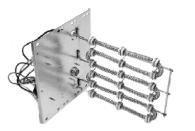
ACCESSORIES
COIL ACCESSORIES
COIL MODEL |
TX2N2 TXV KIT |
TX3N2 TXV KIT |
TX5N2 TXV KIT |
FSK01A FREEZE PROTECTION KIT |
|
|
|
|
|
CA*F030B4* |
--- |
X |
--- |
X |
CA*F036B4* |
--- |
X |
--- |
X |
CA*F042C4* |
--- |
--- |
X |
X |
CA*F048C4* |
--- |
--- |
X |
X |
CA*F057D4* |
--- |
--- |
X |
X |
CA*F060D4* |
--- |
--- |
X |
X |
CHPF030A4* |
--- |
X |
--- |
X |
CHPF036B4* |
--- |
X |
--- |
X |
CHPF042A4* |
--- |
--- |
X |
X |
CHPF048D4* |
--- |
--- |
X |
X |
CHPF060D4* |
--- |
--- |
X |
X |
CH36FCB |
--- |
X |
--- |
X |
CH48FCB |
--- |
--- |
X |
X |
CH60FCB |
--- |
--- |
X |
X |
CA*F18246* |
X |
X |
--- |
X |
CA*F30306* |
--- |
X |
--- |
X |
CA*F36426* |
--- |
X |
X |
X |
CHPF18246* |
X |
--- |
X |
X |
CHPF30306* |
--- |
--- |
X |
X |
CHPF36426* |
--- |
--- |
X |
X |
CSCF1824N6* |
X |
--- |
--- |
X |
CSCF303N6* |
--- |
X |
--- |
X |
CSCF3642N6* |
--- |
X |
X |
X |
|
|
|
|
HKR SERIES ELECTRIC HEAT KITS |
|
|
||||||||
|
|
|
|
|
ELECTRICHEATKITAPPLICATIONS |
|
|
|||||||
|
|
|
|
|
|
|
MBR & MBE |
|
|
|
|
|
||
|
|
|
|
|
|
|
|
|
|
|
|
|
|
|
BLOWER |
|
|
|
|
|
|
ELECTRIC HEAT KIT |
|
|
|
|
|
||
|
|
|
|
|
|
|
|
|
|
|
|
|
|
|
NO HEAT |
HKR-03* |
HKR05-(C)' |
HKR-06* |
|
HKR-08(C)* |
HKR-10(C)* |
HKR-15(C)* |
HKR-20(C)* |
HKR-21(C)* |
^HKR3-15* |
^HKR3-20A |
|||
|
|
|||||||||||||
MBR0800AA-1AA |
- |
X |
X |
X |
|
X |
X |
|
|
|
|
|
|
|
|
|
|
|
|
|
|
|
|
|
|
|
|
|
|
MBR1200AA-1AA |
- |
X |
X |
X |
|
X |
X |
X |
|
X |
X |
|
X |
X |
|
|
|
|
|
|
|
|
|
|
|
|
|
|
|
MBR1600AA-1AA |
- |
X |
X |
X |
|
X |
X |
X |
|
X |
X |
|
X |
X |
|
|
|
|
|
|
|
|
|
|
|
|
|
|
|
MBR2000AA-1AA |
- |
X |
X |
X |
|
X |
X |
X |
|
X |
X |
|
X |
X |
|
|
|
|
|
|
|
|
|
|
|
|
|
|
|
MBE1200AA-1AA |
- |
- |
- |
- |
|
X |
X |
X |
|
- |
- |
|
- |
- |
|
|
|
|
|
|
|
|
|
|
|
|
|
|
|
MBE1600AA-1AA |
- |
- |
- |
- |
|
- |
X |
X |
|
- |
- |
|
- |
- |
|
|
|
|
|
|
|
|
|
|
|
|
|
|
|
MBE2000AA-1AA |
- |
- |
- |
- |
|
- |
X |
X |
|
X |
- |
|
- |
- |
|
|
|
|
|
|
|
|
|
|
|
|
|
|
|
MBE1200AA-1BA |
- |
X |
X |
X |
|
X |
X |
X |
|
- |
- |
|
- |
- |
|
|
|
|
|
|
|
|
|
|
|
|
|
|
|
MBE1600AA-1BA |
- |
X |
X |
X |
|
X |
X |
X |
|
- |
- |
|
- |
- |
|
|
|
|
|
|
|
|
|
|
|
|
|
|
|
MBE2000AA-1BA |
- |
X |
X |
X |
|
X |
X |
X |
|
X |
- |
|
- |
- |
|
|
|
|
|
|
|
|
|
|
|
|
|
|
|
X = Allowable combinations |
^ = Circuit 1: Single Phase for Air Handler Motor |
- = Restricted combinations |
Circuit 2: 3-Phase for HKR3 Heater Kits |
* = Revision level that my or may not be designated C = Circuit Breaker option
23
 Loading...