


GE GTD81GSPJ0MC, GTD81GSPJ1MC, GTD81GSSJ0WS, GTD81GSSJ1WS, GTD81GSSJ2WS Installation Guide
...Installation
Instructions
DE |
I |
GN |
|
S |
|
C |
D |
|
ERTIFIE |
Gas Dryers
06
Questions? Call 800.GE.CARES (800.432.2737) or visit our Web site at: GEAppliances.com
This is the safety alert symbol. This symbol alerts you to potential hazards that can kill you or hurt you and others. All safety messages will follow the safety alert symbol and the word “DANGER”, “WARNING”, or “CAUTION”. These words are defined as:
DANGER |
Indicates a hazardous situation which, if not avoided, will result in death or serious injury. |
|
|
WARNING |
Indicates a hazardous situation which, if not avoided, could result in death or serious injury. |
|
|
CAUTION |
Indicates a hazardous situation which, if not avoided, could result in minor or moderate injury. |
|
|
BEFORE YOU BEGIN
Read these instructions completely and carefully.
• IMPORTANT – Save these instructions for local
electrical inspector’s use.
• IMPORTANT – Observe all governing codes and ordinances.
•Install the clothes dryer according to the manufacturer’s instructions and local codes.
•Note to Installer – Be sure to leave these instructions with the Consumer.
•Note to Consumer – Keep these instructions for future reference.
•Clothes dryer installation must be performed by a qualified installer.
•This dryer must be exhausted to the outdoors.
•Before the old dryer is removed from service or discarded, remove the dryer door.
•Service information and the wiring diagram are located in the control console.
•Do not allow children on or in the appliance. Close supervision of children is necessary when the appliance is used near children.
•Proper installation is the responsibility of the installer.
•Product failure due to improper installation is not covered under the Warranty.
•Install the dryer where the temperature is above 50°F for satisfactory operation of the dryer control system.
•Remove and discard existing plastic or metal foil duct and replace with UL-listed duct.
|
|
|
|
|
|
|
|
|
|
|
WARNING |
|
|
- Fire Hazard |
|
|
|
• |
Clothes dryer installation must be performed by a |
|
|||
|
|
|
qualified installer. |
|
|
||
|
|
• |
Install the clothes dryer according to these |
|
|||
|
|
|
instructions and local codes. |
|
|||
|
|
• |
DO NOT install a clothes dryer with flexible plastic |
|
|||
|
|
|
venting materials. If flexible metal (semi-rigid or |
|
|||
|
|
|
foil-type) duct is installed, it must be UL-listed and |
|
|||
|
|
|
installed in accordance with the instructions found |
|
|||
|
|
|
in “Connecting the Dryer to House Vent” later in |
|
|||
|
|
|
this manual. Flexible vent materials are known to |
|
|||
|
|
|
collapse, be easily crushed and trap lint. These |
|
|||
|
|
|
conditions will obstruct dryer airflow and increase |
|
|||
|
|
|
the risk of fire. |
|
|
||
|
|
• |
DO NOT install or store this appliance in any |
|
|||
|
|
|
location where it could be exposed to water or |
|
|||
|
|
|
weather. |
|
|
||
|
|
• |
To reduce the risk of severe injury or death, follow |
|
|||
|
|
|
all installation instructions. |
|
|||
|
|
• |
Save these instructions. (Installers: Be sure to leave |
|
|||
|
|
|
these instructions with the customer.) |
|
|||
|
|
|
|
|
|
|
|
|
|
|
|
|
|
|
|
Printed in Mexico
234D1753P006
31-16762-1 12-15 GE
Installation Instructions
State of California Proposition 65 Warnings:
The California Safe Drinking Water and Toxic Enforcement Act requires the governor of California to publish a list of substances known to the state to cause cancer, birth defects or other reproductive harm and requires businesses to warn of potential exposure to such substances.
|
This product contains one or more chemicals known to the State of California to cause cancer, birth defects or |
|
WARNING |
||
other reproductive harm. |
Gas appliances can cause low-level exposure to some of these substances, including benzene, carbon monoxide, formaldehyde and soot, caused primarily by the incomplete combustion of natural gas or LP fuels. Exposure to these substances can be minimized by properly venting the dryer to the outdoors.
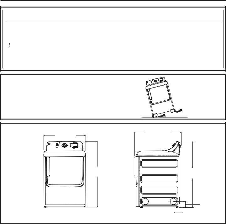
UNPACKING YOUR DRYER
Tilt the dryer sideways and remove the foam shipping pads by pulling at the sides and breaking them away from the dryer legs. Be sure to remove all of the foam pieces around the legs.
Remove the bag containing the literature.
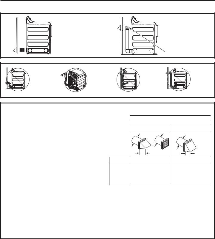
ROUGH-IN DIMENSIONS
28” |
32” (81.3 cm) |
(71.1 cm) |
|
44 1/2” |
44 1/2” |
(113 cm) |
(113 cm) |
|
|
3 1/2” |
Front View |
Side View |
(8.9 cm) |
5 3/4”
(14.6 cm)
2
Installation Instructions
REQUIREMENTS FOR ALCOVE OR CLOSET INSTALLATION
 WARNING
  - Explosion Hazard
Keep flammable materials and vapors, such as gasoline, away from dryer.
Place dryer at least 18” (46 cm) above the floor for a garage installation.
Failure to do so can result in death, explosion, or fire.
•If the dryer is approved for installation in an alcove or closet, it will be stated on a label on the dryer back.
•The dryer MUST be vented to the outdoors. See the EXHAUSTING THE DRYER section.
•Minimum clearance between dryer cabinet and adjacent walls or other surfaces is:
0” either side 3” front
3” rear
•Minimum vertical space from dryer to overhead shelves, cabinets, ceilings, etc., is 1” on top.
•Consideration must be given to provide adequate clearance for installation and service.
•Closet doors must be louvered or otherwise ventilated and have at least 60 square inches of open area. If the closet contains both a washer and a dryer, doors must contain a minimum of 120 square inches of open area.
NOTE: WHEN THE EXHAUST DUCT IS LOCATED IN THE REAR OF THE DRYER, THE CONFIGURATION OF THE DUCTING MAY REQUIRE GREATER THAN 3” OF REAR CLEARANCE.
MINIMUM CLEARANCE OTHER THAN ALCOVE OR CLOSET INSTALLATION
Minimum clearance to combustible surfaces and for air opening are: 0” both sides, 1” front and
3” rear. Consideration must be given to provide adequate clearance for installation and service.
MOBILE OR MANUFACTURED HOME INSTALLATION
•Installation must conform to the MANUFACTURED HOME CONSTRUCTION AND SAFETY STANDARD, TITLE 24, PART 32–80 or Standard CAN/CSA-Z240 MH, or, when such standard is not applicable, with AMERICAN NATIONAL STANDARD FOR MOBILE HOME, ANSI/NFPA NO. 501B.
•The dryer MUST be vented to the outdoors. The exhaust vent must be securely fastened to a non-combustible portion of the mobile home.
•The vent MUST NOT be terminated beneath a mobile or manufactured home.
•The vent duct material MUST BE METAL.
•KIT 14-D346-33 MUST be used to attach the dryer securely to the structure.
•The vent MUST NOT be connected to any other duct, vent or chimney.
•Do not use sheet metal screws or other fastening devices which extend into the interior of the exhaust vent.
•Provide an opening with a free area of at least 25 square inches for introduction of outside air into the dryer room.
•See the sections for electrical connection information.
3
Installation Instructions
CONNECTING A GAS DRYER
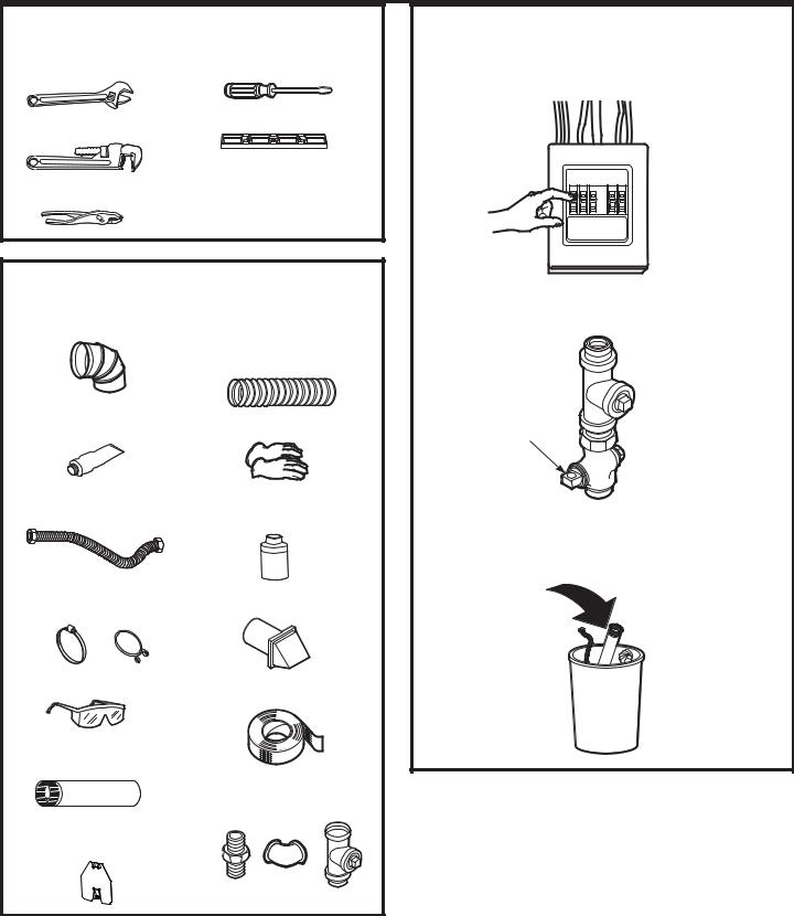
TOOLS YOU WILL NEED
10” Adjustable |
Flat-blade |
wrenches (2) |
screwdriver |
8” Pipe wrench |
Level |
|
|
Slip-joint pliers |
|
MATERIALS YOU WILL NEED
4” dia. metal elbow |
4” dia., UL-listed |
|
|
flexible metal duct |
|
|
(if needed) |
|
Pipe compound or |
Gloves |
|
PTFE tape |
||
Flexible gas line |
Soap solution for |
|
connector |
leak detection |
|
Duct clamps (2) or |
Exhaust hood |
|
Spring clamps (2) |
||
|
Safety glasses |
Duct tape |
|
4” dia. metal duct (recommended)
Gas pipe adapters (2), elbow and pipe plug
4” Cover Plate (Kit
WE49X22606)
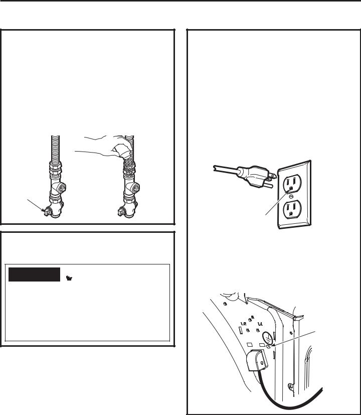
Before beginning the installation, turn off
the circuit breaker(s) or remove the dryer’s circuit fuse(s) at the electrical box. Be sure the dryer cord is unplugged from the wall.
Turn the dryer’s gas shut-off valve in the supply line to the OFF position.
Shut-off
Valve
Disconnect and discard old flexible gas connector and ducting material.
4
Installation Instructions
CONNECTING A GAS DRYER (cont.)
GAS REQUIREMENTS
 WARNING
  - Explosion Hazard
•Use a new CSA International approved flexible gas supply line. Never reuse old flexible connectors.
•Install a shut-off valve.
•Securely tighten all gas connections.
•If connected to LP gas, have a qualified person make sure gas pressure does not exceed 13” water column.
•Examples of a qualified person include: licensed heating personnel, authorized gas company personnel, and authorized service personnel.
•Failure to do so can result in death, explosion, or fire.
•This gas dryer is equipped with a Valve & Burner Assembly for use only with natural gas. Using conversion kit WE25M87, your local service organization can convert this dryer for use with propane (LP) gas. ALL CONVERSIONS MUST BE MADE BY PROPERLY TRAINED AND QUALIFIED PERSONNEL AND IN ACCORDANCE WITH LOCAL CODES AND ORDINANCE REQUIREMENTS.
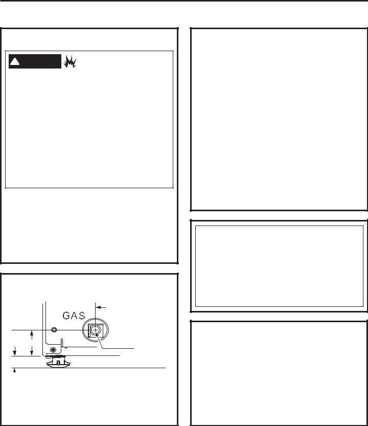
DRYER GAS SUPPLY CONNECTION
3-11/32 
1-25/32”
3/8 NPT MALE
THREAD GAS SUPPLY
 NOTE: Add to vertical dimension the distance between cabineW ERWWRP WR ÀRRU
•You must use with this dryer a flexible metal connector (listed connector ANSI Z21.24/CSA 6.10). The length of the connect shall not exceed 3 ft.
GAS SUPPLY
•A 1/8” National Pipe Taper thread plugged tapping, accessible for test gauge connection, must be installed immediately upstream of the gas supply connection to the dryer. Contact your local gas utility should you have questions on the installation of the plugged tapping.
•Supply line is to be 1/2” rigid pipe and equipped with an accessible shutoff within 6 feet of, and in the same room with, the dryer.
•Use pipe thread compound appropriate for natural or LP gas or use PTFE tape.
•Connect flexible metal connector to dryer and gas supply.
•The installation must conform with local codes, or in the absence of local codes, with the National Fuel Gas Code, ANSI Z223.1/NFPA 54, or the Natural Gas and Propane Installation Code, CSA B149.1.
IN THE COMMONWEALTH OF
MASSACHUSETTS
•This product must be installed by a licensed plumber or gas fitter.
•When using ball-type gas shut-off valves, they shall be the T-handle type.
•A flexible gas connector, when used, must not exceed 3 feet.
ADJUSTING FOR ELEVATION
•Gas clothes dryers input ratings are based on sea level operation and need not be adjusted for operation at or below 2000 ft. elevation. For operation at elevations above 2000 ft., input ratings should be reduced at a rate of 4 percent for each 1000 ft. above sea level.
•Installation must conform to local codes and ordinances or, in their absence, the NATIONAL FUEL GAS CODE, ANSI Z223.
5

Installation Instructions
CONNECTING A GAS DRYER (cont.)
CONNECTING THE DRYER TO THE GAS SUPPLY
AInstall a female 3/8” NPT elbow at the end of the dryer gas inlet.
Install a 3/8” flare union adapter to the female elbow.
IMPORTANT: Use a pipe wrench to securely hold on to the end of the dryer gas inlet to prevent twisting the inlet.
NOTE: Apply pipe compound or PTFE tape to the threads of the adapter and dryer gas inlet.
New Metal |
|
Adapter |
|
Flexible Gas |
|
||
Line Connector |
|
1/8” NPT |
|
|
|
||
|
|
Pipe Plug for |
|
Adapter |
|
Checking Gas |
|
|
Inlet Pressure |
||
Elbow |
|
||
3/8” NPT |
|
||
Items not supplied |
Shut-Off Valve |
||
|
|||
|
Pipe size at |
||
|
|
||
|
|
least 1/2” |
BAttach the flexible metal gas line connector to the adapter.
Apply pipe compound to the adapter and dryer gas inlet.
CTighten the flexible gas line connection, using two adjustable wrenches.
CONNECTING THE DRYER TO THE GAS
SUPPLY (cont.)
DInstall a 1/8” NPT plugged tapping to the dryer gas line shut-off valve for checking gas inlet pressure.
Install a flare union adapter to the plugged tapping.
NOTE: Apply pipe compound or PTFE tape to the threads of the adapter and plugged tapping.
Apply pipe compound |
|
or PTFE tape to all |
|
male threads. |
Plugged |
|
Tapping |
Shut-Off
Valve
ETighten all connections, using two adjustable wrenches. Do not overtighten.
F Open the gas shut-off valve.
6
Installation Instructions
TEST FOR LEAKS
Never use an open flame to test for gas leaks.
Check all connections for leaks with soapy solution or equivalent.
Apply a soap solution. The leak test solution must not contain ammonia, which could cause damage to the brass fittings.
If leaks are found, close the valve, retighten the joint and repeat the soap test.
Open Gas
Valve
ELECTRICAL CONNECTION INFORMATION FOR GAS DRYERS
 WARNING
  - Electrical Shock Hazard
Plug into a grounded 3 prong outlet. DO NOT remove ground prong.
DO NOT use an adapter.
DO NOT use an extension cord.
Failure to do so can result in death, fire or electrical shock.
ELECTRICAL CONNECTION INFORMATION FOR GAS DRYERS (cont.)
The dryer must be electrically grounded in accordance with local codes, or in the absence of local codes, with the National Electrical Code, ANSI/ NFPA 70 or Canadian Electrical Code, CSA C22.1
This appliance must be supplied with 120V, 60Hz, and be connected to a properly grounded branch circuit protected by a 15 or 20 amp circuit breaker or time delay fuse. If electrical supply provided does not meet these requirements, it is the owner’s responsibility to have a licensed electrician install a properly grounded 3-prong outlet.
Ensure proper ground exists before use.
If local codes permit an external ground wire (not provided) may be added by attaching to the green ground screw on the rear of the dryer, and to a grounded metal cold water pipe or other established ground.
Ground
Screw
7
Installation Instructions
EXHAUSTING THE DRYER
 WARNING
 - Fire Hazard
This dryer MUST be vented to the outdoors.
Use only 4” rigid metal ducting for the home exhaust vent.
Use only 4” rigid metal or UL-LISTED transition duct to connect the dryer to the home exhaust duct.
DO NOT use a plastic vent.
DO NOT exhaust into a chimney, kitchen exhaust, gas vent, wall, ceiling, attic, crawl space, or concealed space of a building.
DO NOT install a screen in or over the exhaust duct.
DO NOT use duct longer than specified in the exhaust length table.
Failure to follow these instructions can result in death or fire.
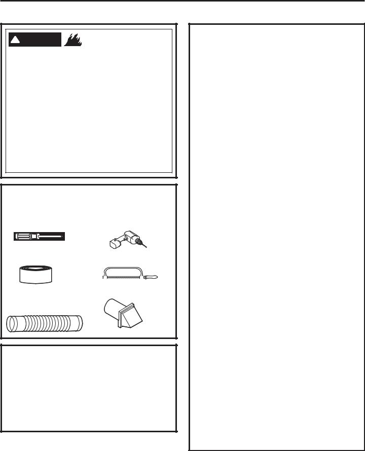
TOOLS AND MATERIALS YOU WILL NEED TO INSTALL EXHAUST DUCT
Phillips-head screwdriver
Duct tape or duct clamp
Rigid or UL-listed flexible metal 4” (10.2 cm) duct
Drill with 1/8” drill bit (for bottom venting)
Hacksaw
Vent hood
PARTS AVAILABLE FROM GEAPPLIANCES.COM OR LOCAL SERVICE ORGANIZATIONS
PM8X85 Outdoor exhaust hood
PM08X10085 8’ Flexible metal clothes dryer transition duct with 2 clamps
WX08X10130 4” Dryer exhaust clamp
WE49X22606 Rear exhaust opening cover, for side or bottom vented dryers
CONNECTING THE DRYER TO HOUSE VENT
RIGID METAL TRANSITION DUCT
•For best drying performance, a rigid metal transition duct is recommended.
•Rigid metal transition ducts reduce the risk of crushing and kinking.
UL-LISTED FLEXIBLE METAL CLOTHES DRYER TRANSITION DUCT
•If rigid metal cannot be used, then UL-LISTED flexible metal clothes dryer transition duct (GE part – PM08X10085) can be used.
•Never install transition duct in walls, ceilings, floors or other enclosed spaces.
•Total length of transition duct should not exceed 8’ (2.4 m).
•For many applications, installing elbows at both the dryer and the wall is highly recommended (see illustrations at right). Elbows allow the dryer to sit
close to the wall without kinking and/or crushing the transition duct, maximizing drying performance.
•Avoid resting the duct on sharp objects.
UL-LISTED FLEXIBLE METAL (FOIL-TYPE) TRANSITION DUCT
•In special installations, it may be necessary to connect the dryer to the home exhaust vent using flexible metal (foil-type) transition duct. UL–LISTED universal flexible dryer transition duct (GE parts – PM8X73 or WX8X73) may be used ONLY in installations where rigid metal or flexible metal transition ducting cannot be used AND where a 4” diameter can be maintained throughout the entire length of the transition duct.
•In Canada and the United States, only transition ducts that
comply with “UL 2158A STANDARD FOR CLOTHES DRYER TRANSITION DUCT” shall be used.
•Avoid resting the duct on sharp objects.
•For best drying performance:
1.Slide one end of the duct over the clothes dryer outlet pipe.
2.Secure the duct with a clamp.
3.With the dryer in its permanent position, extend the duct to its full length. Allow 2” of duct to overlap the exhaust pipe. Cut off and remove excess duct. Keep the duct as straight as possible for maximum airflow.
4.Secure the duct to the exhaust pipe with the other clamp.
8
Installation Instructions
•DO cut duct as short as possible and install straight into wall.
•DO use elbows when turns are necessary.


 Elbows
•DO NOT bend |
•DO NOT use |
•DO NOT |
•DO NOT |
or collapse |
excessive |
crush duct |
set dryer |
ducting. Use |
exhaust |
against the |
on duct. |
elbows if turns |
length. Cut |
wall. |
|
are necessary. |
duct as short |
|
|
|
as possible. |
|
|
EXHAUST LENGTH
Using exhaust longer than specified length will:
•Increase the drying times and the energy cost.
•Reduce the dryer life.
•Accumulate lint, creating a potential fire hazard.
The correct exhaust installation is YOUR RESPONSIBILITY.
Problems due to incorrect installation are not covered by the warranty.
The MAXIMUM ALLOWABLE length of the exhaust system depends upon the type of duct, number of turns, the type of exhaust hood (wall cap) and all conditions noted on the chart.
•Internal elbows added for side or bottom vent conversions must be included in the total elbow count.
•Any elbow greater than 45° should be treated as a 90° elbow.
•Two 45° elbows will be treated like one 90° elbow.
•For every additional 90° elbow, reduce the allowable vent system length by 10 feet.
•When calculating the total vent system length, you must add all the straight portions and elbows of the system (including the transition duct).
|
EXHAUST LENGTH |
||
|
FOR NORMAL VENT MODELS |
||
|
RECOMMENDED MAXIMUM LENGTH |
||
|
|
Exhaust Hood Types |
|
|
Recommended |
Use only for short |
|
|
run installations |
||
|
|
|
|
|
|
|
4" DIA. |
|
4" DIA. |
4" DIA. |
|
|
4" |
|
2-1/2" |
No. of 90° |
Rigid |
|
Rigid |
Elbows |
Metal |
|
Metal |
0 |
90 Feet |
|
60 Feet |
1 |
60 Feet |
|
45 Feet |
2 |
45 Feet |
|
35 Feet |
3 |
35 Feet |
|
25 Feet |
4 |
25 Feet |
|
15 Feet |
9
 Loading...