


90-70
Table of contents
 Loading...
GE Fanuc Automation
Programmable Cont rol Products
Series 90™-70
Enhanced Hot Standby
CPU Redundancy User' s Guide
GFK-1527A May 2000

GFL-002
Warnings, Cautions, and Notes
as Used in this Publication
Warning
Warning notices are used in this publication to emphasize that hazardous voltages,
currents, temperatures, or other conditions that could cause personal injury exist in this
equipment or may be associate d with its use.
In situations where inattention could cause either personal injury or damage to
equipment, a Warning notice is used.
Caution
Caution notices are used where equipment might be damaged if care is not taken.
Note
Notes merely call attention to information that is especially significant to understanding and
operating the equipment.
This document is based on information available at the time of its publication. While efforts
have been made to be accurate, the information contained herein does not purport to cover all
details or variations in hardware or software, nor to provide for every possible contingency in
connection with installation, operation, or maintenance. Features may be described herein
which are not present in all hardware and software systems. GE Fanuc Automation assumes no
obligation of notice to holders of this document with respect to changes subsequently made.
GE Fanuc Automation makes no representation or warranty, expressed, implied, or statutory
with respect to, and assumes no responsibility for the accuracy, completeness, sufficiency, or
usefulness of the information contained herein. No warranties of merchantability or fitness for
purpose shall apply.
The following are trademarks of GE Fanuc Automation North America, Inc.
Alarm Master Genius PROMACRO Series Six
CIMPLICITY Helpmate PowerMotion Series Three
CIM P LIC IT Y 90 – ADS Logicm aster PowerTRA C VersaMax
CIMSTAR Modelmaster Series 90 VersaPro
Field Control Motion Mate Series Five VuMaster
GEnet ProL oop Series One Workm aster
©Copyr ight 1998 - 2 000 GE Fanuc Autom ation N orth Am erica, In c.
All Rights Reserved .

Preface
GFK-1527A iii
This manual is a reference to the hardware components, configuration and operation of Enhanced
Hot Standby CPU Redundancy for the Series 90-70 Programmable Logic Controller. This revision
adds information about new redundancy CPUs IC697CGR772 and IC697CGR935, as well as new
features available with Release 7.85 of the product. Also, corrections have been made where
necessary.
The information in this manual is intended to supplement the information contained in the system
installation, programming, and configuration information found in the manuals listed below under
Related Publications.
Content of This Ma nual
Chapter 1. Introduction: introduces a method of CPU Redundancy for the Series 90-70
Programmable Logic Controller, which is referred to as Enhanced Hot Standby CPU Redundancy.
Chapter 2. System Components: describes th e h ar d wa re compon en ts for an Enhanced Hot
Standby CPU Redundancy system.
Chapter 3. Configuration Requirements: defines the special configuration requirements of an
Enhanced Hot Standby CPU Redundancy system.
Chapter 4. Normal Operation: describes the operation of an Enhanced Hot Standby CPU
Redundancy system.
Chapter 5. Fault Detection: describes how faults are handled in an Enhanced Hot Standby CPU
Redundancy system.
Appendix A. Cabling: provides a description and diagram of the Series 90-70 multidrop cable for
use in redundancy systems.
Relat e d Publi ca t ions
For more information, refer to these publications:
Genius I/O System User' s Manual
(GEK-90486-1). Reference manual for system designers,
programmers, and others involved in integrating Genius I/O products in a PLC or host co mputer
environ ment. This book provides a syste m overvie w, and describes t he type s of syst ems that can be
created using Genius products. Datagrams, Global Data, and data formats are defined.
Genius Discrete and Analo g Bl ocks User' s Ma nual (GEK-90486-2). Reference manual for system
designers, operators, mai ntenance pe rso nnel, a nd others usi ng Genius disc rete a nd analog I/O
blocks. This book contains a detailed description, specifications, installation instructions, and
conf i gura tion i nstructions for dis cre t e a nd an alo g blocks .
Series 90-70 PLC Installation Manual
(GFK-0262). This book describes the hardware
components in a Series 90-70 PLC system, and provides the details of system installation.

Preface
iv Series 90™-70 Enhanced Hot Standby CPU Redundancy User's Guide–May 2000 GFK-1527A
Logicmaster 90-70 Programming Software User's Manual
(GFK-0263). A programming software
user's manual for system operators and others using the Logicmaster 90-70 software to program,
configure, monitor, or control a Series 90-70 PLC system.
Series 90-70 PLC CPU Instruction Set Reference Manual
(GFK-0265). Reference manual which
describes operation, fault handling, and programming instructions for the Series 90-70 PLC.
Series 90-70 System Manual for Control Software Users (GFK-1192). Provides an overview of
hardware and software features of the Series 90-70 PLC.
Series 90-70 Remote I/O Scanner User's Manual (GFK-0579). Reference manual for the Remote
I/O Scanner, which interfaces a drop containing Series 90-70 modules to a Genius bus. Any CPU
capable of controlling t he bus can be used as the hos t. This book d e s c ribes the Re mote I /O Scanner
features, configuration, and operation.
Series 90-70 Bus Controller User's Manual (GFK-0398). Reference manual for the bus
controller, which interfaces a Genius bus to a Series 90-70 PLC. This manual describes the
ins tallation and op erat ion of the Bus Controller. It also contai ns the progr am min g infor m ation
needed to interface Genius I/O devices to a S er ies 90-70 P LC.
Control User’s Gui de (GFK-1295). Describes configuration and programming software using
Control Programming. Control software, release 2.1 or later is required to configure Ethernet
Global Data as described in this manual.

Contents
GFK-1527A v
Chapter 1 Introduction..................................................................................................... 1-1
Enhanced Hot Standby CPU Redundancy.....................................................................1-2
Features of Enhanced Hot Standby CPU Redundancy...................................................1-3
Using the Redundancy CPU for Non-Redundant Operation ....................................1-3
Compatibility with CPU780...................................................................................1-3
Redundancy CPUs as Compared to Other Series 90-70 CPUs.......................................1-4
Features not Available with Redundancy CPUs......................................................1-4
Differences in Operation for Redundancy CPUs.....................................................1-4
Components of the Enhanced Hot Standby Redundancy System...................................1-5
Enhanced Redundancy CPU Module......................................................................1-5
Redundancy Communications Module....................................................................1-5
Redundant Racks....................................................................................................1-5
I/O Systems for Enhanced Hot Standby CPU Redundancy......................................1-5
Genius I/O............................................................................................................1-6
Local I/O..............................................................................................................1-6
Cable Connections................................................................................................1-6
Enhanced Hot Standby CPU Redundancy System with Local I/O ..........................1-7
Control Strategies.........................................................................................................1-8
GHS Control Strategy........................................................................................... 1-8
GDB Control Strategy...........................................................................................1-8
Basic Enhanced Hot Standby Operation ........................................................................1-9
Output Control with GHS......................................................................................1-9
Output Control with GDB.....................................................................................1-9
Basic CPU Redundancy Setups...................................................................................1-10
Single Bus with Preferred Master: GHS Control Strategy.....................................1-10
Single Bus with Floating Master: GDB Control Strategy......................................1-11
Dual Bus with Floating Master: GDB Control Strategy........................................ 1-12
Duplex CPU Redundancy.................................................................................... 1-13
Online Programming...................................................................................................1-13
On-Line Repair...........................................................................................................1-13
Chapter 2 System Components........................................................................................ 2-1
System Racks...............................................................................................................2-1
Redundancy CPU.........................................................................................................2-2
Features................................................................................................................2-2
CPU Architecture .........................................................................................................2-3
Expansion Memory Board.....................................................................................2-3
Watchdog Timer...................................................................................................2-3
CPU Features ...............................................................................................................2-4
Memory Protect Keyswitch...................................................................................2-4
CPU LEDs............................................................................................................2-4
Battery Connectors................................................................................................2-4
CPU Mode Switch................................................................................................2-5
Run/Outputs Enabled Mode............................................................................2-5
Run/Outputs Disabled Mode...........................................................................2-5
Stop Mode .....................................................................................................2-5
Port 1....................................................................................................................2-5

Contents
vi Series 90™-70 Enhanced Hot Standby CPU Redundancy User's Guide–May 2000 GFK-1527A
Port 2....................................................................................................................2-5
Port 3....................................................................................................................2-5
Redundancy Communications Module..........................................................................2-6
Unit Select Pushbutton.......................................................................................... 2-6
Connector............................................................................................................. 2-7
RCM Status LEDS................................................................................................2-7
Bus Transmitter Module...............................................................................................2-8
Connectors............................................................................................................2-8
Bus Transmitter Module Status LEDs....................................................................2-8
Bus Receiver Module....................................................................................................2-9
Connectors............................................................................................................2-9
Cables and Termination ........................................................................................2-9
Genius Bus Controller ................................................................................................ 2-10
Location of GBCs and Blocks .............................................................................2-10
Single Bus Genius Networks ............................................................................... 2-11
Dual Bus Genius Networks .................................................................................2-11
Connectors..........................................................................................................2-12
Bus Controller LEDs...........................................................................................2-12
Chapter 3 Configuration Requirements.......................................................................... 3-1
Programmer Connection for Configuration...................................................................3-1
One Application Program in Both PLCs........................................................................3-1
Program Folders in Control Programming Software...............................................3-1
Program Folders in Logicmaster 90.......................................................................3-2
CPU Configuration Parameters.....................................................................................3-2
Configuring Shared I/O References ........................................................................ 3-3
Finding the Memory Available for Application Program Storage............................3-4
System Communications Window Considerations ..................................................3-4
Configuring the Redundancy CPU for Non-redundant Operation..................................3-5
Rack Module Configuration Parameters........................................................................3-5
Bus Controller Configuration Parameters......................................................................3-5
Genius I/O Block Configuration Parameters..................................................................3-6
Chapter 4 Normal Operation........................................................................................... 4-1
Powerup of a Redundant CPU.......................................................................................4-2
Incompatible Configurations.........................................................................................4-3
Resynchronization of a Redundant CPU........................................................................4-3
GHS Control Strategy...................................................................................................4-4
GDB Control Strategy................................................................................................... 4-4
%S References for CPU Redundancy............................................................................4-5
OVR_PRE %S Reference Not Available...............................................................4-5
Scan Synchronization...................................................................................................4-6
Input Data and Synchronization Data Transfer to the Backup Unit................................4-6
Sweep Time Synchronization................................................................................4-6
Output Data Transfer to the Backup Unit......................................................................4-7
Data Transfer Time.......................................................................................................4-8

Contents
GFK-1527A Contents vii
Fail Wait Time......................................................................................................4-8
Programming a Data Transfer from Backup Unit to Active Unit..................................4-10
Data Transfer Example................................................................................. 4-10
Disabling Data Transfer Copy in Backup Unit (SVCREQ #43)...................................4-11
Command Block for SVCREQ #43..................................................................... 4-12
Backup Qualification with SVCREQ #43............................................................4-13
Validating the Backup PLC's Input Scan ............................................................. 4-13
Validating the Backup PLC's Logic Solution....................................................... 4-13
Switching Control to the Backup Unit.........................................................................4-14
Switching Times ................................................................................................. 4-14
Commanding a Role Switch from the Application Program (SVCREQ #26)........4-14
Example.......................................................................................................4-14
RUN Disabled Mode..................................................................................................4-15
RUN Disabled Mode for GHS Control Strategy....................................................4-15
Example 1: Role switches allowed on both units.................................................. 4-15
Example 2: Role switches allowed on both units.................................................. 4-16
Example 3: Role switches not allowed on either unit............................................4-16
Example 4: Role switches allowed on both units.................................................. 4-16
Example 5: Role switches allowed on both units Secondary Unit Active.............. 4-17
Example 6: Role switches not allowed on either unit, Secondary Unit Active.......4-17
Example 7: Role switches allowed on both units, Secondary Unit Active............. 4-17
Example 8: Invalid..............................................................................................4-18
RUN Disabled Mode for GDB Control Strategy...................................................4-18
Background User Checksum and Background Window Timing Instructions................4-19
Finding the Words to Checksum Each Sweep...................................................... 4-19
Finding the Background Window Time...............................................................4-20
Finding the Total Sweep Time.............................................................................4-20
Miscellaneous Operation Information.........................................................................4-21
Timer and PID Function Blocks.......................................................................... 4-21
Timed Contacts...................................................................................................4-21
Multiple I/O Scan Sets........................................................................................4-21
C Debugger ........................................................................................................4-22
STOP to RUN Mode Transition ..........................................................................4-22
Background Window Time.................................................................................4-22
Sequential Function Chart Programming (SFC)...................................................4-22
Genius Bus Controller Switching................................................................................4-23
Ethernet Global Data in a Redundancy CPU............................................................... 4-24
Ethernet Global Data Consumption..................................................................... 4-24
Ethernet Global Data Production.........................................................................4-25
SNTP Timestamping...........................................................................................4-25
Chapter 5 Fault Detection................................................................................................ 5-1
Configuration of Fault Actions......................................................................................5-1
Fault Detection.............................................................................................................5-2
PLC Fault Table Messages for Redundancy..................................................................5-3
Fault Response .............................................................................................................5-5
Faulting RCMs, Losing Links, and Terminating Communications.................................5-6
Faulting the Redundancy Communications Module...............................................5-6
Losing a Link........................................................................................................5-6

Contents
viii Series 90™-70 Enhanced Hot Standby CPU Redundancy User's Guide–May 2000 GFK-1527A
Fault Actions in a CPU Redundancy System.................................................................5-7
Configurable Faults...............................................................................................5-8
Non-Configurable Fault Group..............................................................................5-9
Fatal Faults on Both Units in the Same Sweep.......................................................5-9
On-Line Repair...........................................................................................................5-10
Maintaining Parallel Bus Termination...................................................................5-11
On-Line Repair Recommendations....................................................................... 5-11
Power Supply.......................................................................................................5-11
Racks...................................................................................................................5-11
Central Processor Unit..........................................................................................5-12
Redundancy Communications Module and Cables................................................5-12
Redundancy Communications Link Failures.........................................................5-12
Bus Transmitter Module.......................................................................................5-13
Genius Bus Controller..........................................................................................5-13
Genius Bus ........................................................................................................... 5-13
Single Bus Networks Bus faults .......................................................................... 5-13
Dual Bus Networks ............................................................................................. 5-14
Genius Blocks......................................................................................................5-14
Appendix A Cabling Information .......................................................................................A-1
IC690CBL714A Multi-drop Cable............................................................................... A-1
Purpose.................................................................................................................A-1
Specifications........................................................................................................ A-1
GFK-1527A 1-1
Introduction
This chapter introduces the method of CPU Redundancy for the Series 90-70 Programmable Logic
Controller, which is referred to as Enhanced Hot Standby CPU Redundancy. The contents of this
chapter describe:
Enhanced Hot Standby CPU Redundancy
Components of the Enhanced Hot Standby Redundancy System
Control Strategies
Basic Enhanced Hot Standby Operation
Basic CPU Redundancy Systems
Definition of Terms
Active Unit
The unit that is currently contr oll in g the pr o cess .
Backup Unit
That unit that is synchron ized with the active unit and able to take over the process.
CPU Redundancy
A system with two PLC CPU units cooperating to control the same process.
Critical Component
A component whose failure causes the PLC (either active o r b ac kup) where it res ides to stop.
Hot Standby
A featu re of Ge ni us devi c e s w hereb y the device pre f ers outp u t da t a from the Bus Cont roller at Ser i a l Bus
Address 31. When outputs from that Bus Contr oller are not avai lable, the devi ce takes output data from the
Bus Contro ller at Serial B us Address 30. If outputs from neither Controlle r are available, the device places its
outputs in the designate d default state .
Primary Unit
The unit in which the externally redundant Bus Controllers' Serial Bus Address is 31.
Redundancy
The us e of multi ple ele m ents control ling th e same proces s to provid e alterna te fun ct ional channels in case of
failure.
Secondary Unit
The unit in which the externally redundant Bus Controllers' Serial Bus Address is 30.
Synchronized
A unit is considered to be synchronized when it has received the latest status information from the Active unit
and is running the PLC program in parallel.
Dual Bus
The use of two Genius busses to control the same I/O devices. The busses are linked to the I/O devices by one
or more Bus Switch ing Modu les (BSMs) . A BSM will automatically switch to the other bus if the active bus
has a failure.
Local System
(LE Ds on RCM) - The system where the RCM resides. LEDs indicate whethe r the lo cal u n it is ready to
become the active unit or is the act ive unit in a redundancy system.
Remote System
(LEDs on RCM) - The system to which the RCM is connected via the communications cable. LEDs indicate
whethe r the remote unit is ready to become the active unit or is th e active unit in a red undancy system.
1
Chapter

1-2 Series 90™-70 Enhanced Hot Standby CPU Redundancy User's Guide
–
May 2000 GFK-1527A
1
Enhanced Hot Standby CPU Redundancy
CPU Redundancy allows a critical application or process to continue operating if a failure occurs in
any sin g le component. An Enhanced Hot Stand by CP U Redundan cy syst em consis ts of two CPUs
conn ected to one or more Geniu s I/ O networks. One P LC is the Primary PLC and the other is the
Secondary PLC. The Primary PLC contains all externally redundant Genius Bus Controllers at
Seri al Bus Addres s 31 ; the Secondary PLC contains all externall y r ed undant Genius Bus
Controllers at Serial Bus Address 30.
Each PLC
must have a Redundancy CPU module (IC697CGR772 or IC697CGR935), a
Redundancy Communications module and a Bus Transmitter Module
. The Redundancy
Communications module provides the synchronizing link between the two units. The scanning
process of both CPUs is synchronized to minimize bumpless switching from one PLC to the other.
The CPU that currently controls the system is called the active unit, the other CPU is the backup
unit. Control automatically switches to the backup unit if certain system failures are detected in the
active unit. Control can also be switched manually by pressing a pushbutton on the Redundancy
Communications Module, or through the application program. When a manual switch of control
occurs, the CPUs switch roles; the active unit becomes the backup unit and the backup unit
becomes active.
The system runs synchronously with a transfer of all control data that defines machine status and
any in ternal data n eeded to keep the two CPUs operating in s ync. The transfer of data from the
acti ve un it to the standby unit occurs twice per sweep. These CPU to CPU tr ansfers ar e checked
for data integrity.

GFK-1527A Chapter 1 Introduction 1-3
1
Features of Enhanced Hot Standby CPU R edundancy
Bumpless switching
Synchronized CPUs
4.7 ms (CGR935), 5.9 ms (CGR772) base sweep time in Run mode
One scan switching (in most ca ses)
Configurable backup data size
No single point of failure (excluding Genius I/O blocks and bus stubs)
Redundant backup communications
Online repair of failed component
Onl i ne pr ogramming
Same or di ff erent programs in Primary and S econdary uni ts
Redundancy Communications Module
Manual pushbutton for switching control between active and backup CPUs
Five Status LEDs
Status Bits (%S) reflect redundancy status of Primary/Secondary units
Program control switching
Memory parity and checksums
Common I/O on Genius bus
Genius Dual Bus support
Background Diagnostics
Memory Protect Keyswitch
Using the Redundancy CPU for Non-Redundant Operation
The Redundancy CPU can be used for both redundant and non-redundant applications. The
functionality and performance of a Redundancy CPU configured for standalone operation is the
same as for a unit that is configured for redundant operation which has no backup currently
available. This includes the redundancy informational messages such as those generated when a
unit goes to Run mode. Refer to Chapter 3, "Configuring the Redundancy CPU for Non-redundant
Operation."
Compatibility with CPU780
Note that the IC697CGR772 is not compatible with the CPU780. Also, mixing of IC697CGR935
and IC697CGR772 CPUs is not allowed in the same redundant system, since there are several
differences betw een the t wo models.

1-4 Series 90™-70 Enhanced Hot Standby CPU Redundancy User's Guide
–
May 2000 GFK-1527A
1
Redundancy CPUs as Compared to Other Series 90-70 CPUs
The Redundancy CPU has several differences in operation compared to other Series 90-70 CPUs.
Features not Available with Redundancy CPUs
The following features are not available:
I/O Interrupts:
This includes the single edge triggered interrupts from the discrete input
modules, the high alarm and low alarm interrupts from the analog input modules, and
interrupts from third party VME modules. A program that declares I/O Interrupt triggers
cannot be store d to a Red undancy CP U.
Timed Interrupts
VME Integrator Racks.
Stop I/O Scan mode:
If an attempt is made to place the PLC in this mode, the PLC will reject
the sel ection and r eturn an error .
Flash operation: User Flash (Store/Load, Verify) as opposed to Flash firmware upgrade
FBCs and FIP I/O
Timed and Event-triggered Programs:
Logic that contains Timed or Event-triggered programs
cannot be store d.
Microcycle Mode and Periodic Programs
14-point interrupt module
OVR_PRE %S reference which indicates whether one or more overrides is active
Differences in Operation for Redundancy CPUs
The following features operate differently with the CGR772 or CGR935 than they do with other
Series 90-70 CPUs:
RUN/DISABLED mode. This is explained in chapter 4,
Operation
.
Configuration of Fault Actions
STOP to RUN mode transition
Background Window Time (default is different)
C Debugger
Ethernet Global Data operation is enhanced
Rack 7 is not available

GFK-1527A Chapter 1 Introduction 1-5
1
Components of the Enhanced Hot Standby Redundancy System
Enhanced Redundancy CPU Module
To utilize the features described in this manual, an Enhanced Redundancy CPU Module
(IC697CGR935 or IC697CGR772) must be installed rack 0, slot 1 of both the Primary and
Second ary PLCs. Fea tures of the redundancy CPU that ar e different from conven tional C P US are
listed on the previous page.
Redundancy Co mmunications Modul e
Two Redundancy Communications Modules (RCM) are available that provide a path for sharing
data between the two CPUs in the redundant system. Catalog number IC697RCM711 is for use in
standard Series 90-70 racks and IC687R CM 711, whic h is for use in dual redundant racks
(described below).
The RCM module has a pushbutton switch that can be used to manually switch control from the
active unit to the backup unit. The switch between units can also be controlled through the
application p ro g ram logic.
In a synchronized system, I/O data is controlled by only one unit (the active unit) but is shared
between both units (active and backup units). The Redundancy Communications Module provides
a communications path to synchronize the two CPUs. It also provides the communications path for
the transfer of I/ O da ta. An RCM must be located in th e main rack of both the Primar y PLC and
the Secon dary PLC, or in both sections of a dua l r edundant r ack.
Redundant Ra ck s
Redundant racks; IC697CHS770 (rear mount) and IC697CHS771 (front mount) have two power
supply slots and 12 backplane slots divided into two separate sections, each having a power supply
slot and 6 backplane slots. The redundant rack is designed for easy integration of third-party VME
modules into a Series 90-70 PLC system. These racks accept all standar d Ser ies 90-70 modules
and ½ slot VME mod u les. VME modul es r eq uire 0.8” spa cing and use one slot, while standard
Series 90-70 modules use two of the available slots. Cable connection between the required ½ slot
RCM modules and the required ½ slot BTM modules (catalog number IC687BEM713) in a
redundant rack is through an available 3 foot (0.9 meter) cable, IC697CBL803.
I/O Systems for Enhanced Hot Standby CPU Redundancy
Both Series 90-70 Local I/O and Genius I/O systems can be present in an Enhanced Hot Standby
CPU Redundancy system. The two PLCs need not have matching I/O systems -- they may have
different numbers of I/O racks, different I/O modules and different option modules.

1-6 Series 90™-70 Enhanced Hot Standby CPU Redundancy User's Guide
–
May 2000 GFK-1527A
1
Genius I/O
The redundant portion of the system is based on Genius I/O. A system using standard Series 90-70
racks can have multiple Genius I/O bus networks. A system using the ½ slot redundant racks may
have only one bus in the CPU ra c k. Any Geniu s de vice ca n be placed on the bus (Genius blocks,
Field Control, Remote I/O Scanner, VersaMax I/O, etc.). The Genius devices are under control of
the active unit in the Redund ancy system. The Genius Bus C ontroller in the Primar y Un it has a
Serial Bus Address of 31; the Geni us Bus Controller in the Secondary Unit has a Serial Bus
Address of 30. Data from S e ria l Bus Address 31 is th e prefer red data when dat a is being sent from
both units to devices on the Genius bus.
Local I/O
Local I/O can be included in the overall PLC system; however,
it is not
part of t he Hot S tan dby
CPU Redundancy system. Control of Local I/O is done normally through the application program.
Transfer of this data between the redundan cy CPUs is optional. A failure in the Local I/O system
will affect the system as described in GFK-0265, the
Series 90-70 Programmable Controller
Reference Manual
.
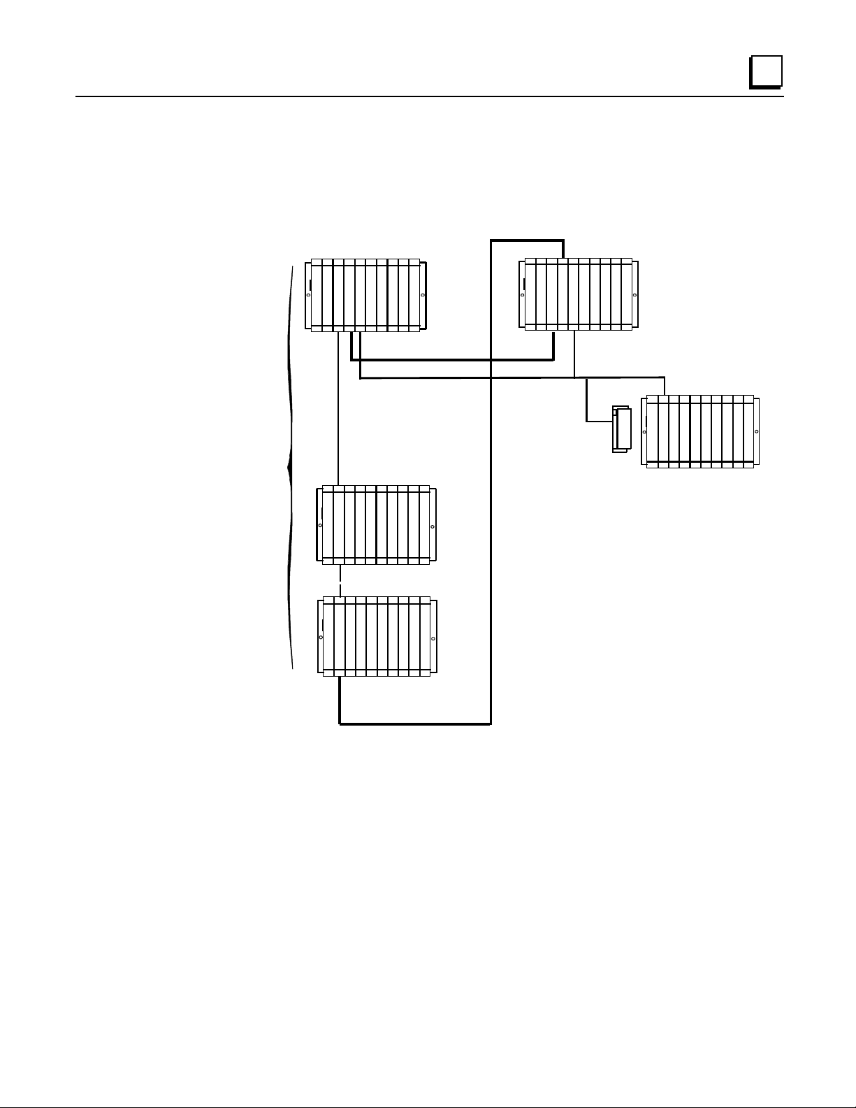
Cable Connections
In an Enhanced Hot Standby CPU Redundancy system that requires expansion racks, a Bus
Tran sm itter Module in rack 0 is connected by a p ar allel I/O cable to a Bus Receiver Module in the
next r ack. The link is con tinued fr om this Bus Receiv er Module to a Bus Receiver M odu le in the
next rack. This link is continued with a maximum of six expansion racks. The last Bus Receiver is
connected via an I/O cable with built-in termination (catalog number IC697CBL803 (3 feet (0.9m))
catalog IC697CBL811 (10 feet (3m)) or IC697CBL826 (25 feet (7.5m)). The last module in the
parallel I/O bus link must be a Redundancy Communications Module (RCM). This terminated I/O
cable allows replacement of the RCM without interrupting the running system. If no expansion
racks are used, th e terminat ed I/O cable is connected directly from the Bus Transmitter Mod u le to
the Redundancy Communications Module.
GFK-1527A Chapter 1 Introduction 1-7
1
Enhanced Hot Standby CPU Redundancy System with Local I/O
The following illustration is an example of an Enhanced Hot Standby CPU Redundancy system
with Local I/O in standard Series 90-70 expansion racks.
C
P
U
B
T
M
R
C
M
G
B
C
30
Secondary Unit
Primary Unit
31
P
S
P
S
S
C
A
N
N
E
R
REMOTE DROP
I
O
I
O
I
O
I
O
I
O
I
O
I
O
I
O
P
S
B
T
M
G
B
C
L
O
B
C
K
I
O
I
O
I
O
I
O
I
O
I
O
I
O
I
O
P
S
C
P
U
B
R
M
RACK 0
RACK 1
RACK 0
I
O
I
O
I
O
I
O
I
O
I
O
I
O
I
O
P
S
RACK 6
LOCAL I/0
CAN BE IN
RACKS
0 - 6
I
O
I
O
I
O
I
O
I
O
I
O
I
O
I
O
I
O
I
O
B
R
M
R
C
M
I/O CABLE WITH BUILT-IN TERMINATION
IC697CBL811 (10 FEET (3m))
IC697CBL826 (25 FEET (7.5m))
*
*
TERMINATED I/O CABLE
TERMINATED I/O CABLE
*
---
---
IC697CBL803 (3 FEET (0.9m))
Note
Rack 7 is not available for I/O modules in an Enhanced Hot Standby CPU
Redundancy system.

1-8 Series 90™-70 Enhanced Hot Standby CPU Redundancy User's Guide
–
May 2000 GFK-1527A
1
Control St rategies
There are two different Control Strategies for Enhanced Hot Standby CPU Redundancy: GHS
and
GDB.
GHS Control Strategy
The GHS control strategy has the following features:
Multiple single bus Genius I/O networks with redundant controller in each synchronized PLC
Multiple local single bus Genius I/O networks
Redundant Genius I/O driven exclusively by the active unit
Primary Unit is always the Active Unit in synchronized system unless explicitly overridden by
user or application; switchover from secondary active to primary active may not be bumpless
in certain failure conditions
Only critical control data must be transferred from Active to Backup CPU
Compatible with the release 4 based Hot Standby Redundancy Product (CPU780)
GDB Cont rol Strategy
The GDB control strategy has the following features:
Multiple dual bus Genius I/O Networks with redundant controllers in each synchronized PLC
Multiple single bus Genius I/O networks with redundant controller in each synchronized PLC
Multiple local Genius I/O networks with single or dual buses or controllers
Active unit does not automatically switch to Primary on resynchronization
Bumpless switchover with either PLC active
Critical control data plus all redundant outputs must be transferred from Active to Backup
CPU

GFK-1527A Chapter 1 Introduction 1-9
1
Basic Enhanced Hot Standby Operation
In an Enhanced Hot Standby CPU Redundant system, Genius I/O Blocks are normally configured
for Hot Standby operation. Genius I/O Blocks can also be configured for the less frequently used
Duplex operation, but only with the GDB Control Strategy. When configured for Hot Standby
operation, the blocks must choose between outputs from the Genius Bus Controller at serial bus
address 31 and the Genius Bus Controller at serial bus address 30. If outputs from both Genius Bus
Controllers are available, then the blocks will prefer the outputs from bus address 31. If there are
no outputs from bus address 31 for three consecutive Genius I/O bus scans, the blocks will use the
outputs from bus address 30. If out puts are not available from ei t her bus address 3 1 or 30, t he
outputs go to their configured default (OFF or hold last state).
For Hot Standby CPU Redundant systems, the Genius Bus Controllers in the Primary Unit are
normally configured at serial bus address 31 and the Genius Bus Controllers in the Secondary Unit
are normally configured at serial bus address 30.
It is possible to configure Genius I/O networks in which there is not a redundant bus controller in
the synchronized PLC. It i s not necessar y for th e serial bus addresses to be 31 in the Prim ary unit
and 30 in the secondary for such networks.
In an Enhanced Hot Standby CPU Redundancy system, only the active unit may control the
redundant Genius outputs. This is accomplished differently in the two control strategies:
Output Control with GHS
In the GHS control strategy, the PLC CPU allows only the active unit to control the outputs. When
the Primary Unit is active (GBCs at bus address 31), the PLC CPU allows both units to send
outputs to the blocks. The result is a bumpless switchover if the Primary Unit fails while it is the
active unit.
If the Secondary Unit is active, the PLC CPU automatically disables outputs from the redundant
GBCs in the Primary Unit. That means the Genius I/O blocks will only receive out p u ts from th e
Secondary Unit (bus controllers at serial bus address 30).
Output Control with GDB
In the GDB control strategy, both the Primary and Secondary Units send outputs regardless of
which one is active. The user is resp onsible for ensurin g tha t all redundant outpu ts are tran s ferred
from the active unit to the backup unit. Because the same output values will then be present in both
units, the blocks will receive the same outputs (regar dl es s of wheth er the Primary or the Secondary
Unit is active). There is no output glitch (data interruption) on switchover since both units are
always sending outputs.
1-10 Series 90™-70 Enhanced Hot Standby CPU Redundancy User's Guide
–
May 2000 GFK-1527A
1
Basic CPU Redundancy Setups
Ther e are three basi c C P U Redundan cy setu p s :
Singl e Bus with Preferred Master
Single Bus with Floating Master
Dual Bus with Floating Master
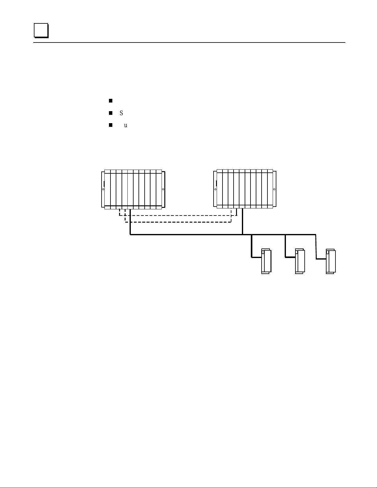
Single Bus with Preferred Master: GHS Control Strategy
This type of system uses a single Genius bus with bus controllers in each PLC. The Primary Unit
is always chosen as the active unit when the units initially synchronize.
C
P
U
C
P
U
B
T
M
R
C
M
G
B
C
30
Secondary Uni t Prima r y Uni t
31
B
L
O
C
K
B
L
O
C
K
P
S
P
S
B
T
M
R
C
M
G
B
C
B
L
O
C
K
Only Critical Data Transferred
B
TM............ Bus Transmitter Module
GBC............ Genius Bus Controller
PS.............. Power Supply..
CPU........... Central Processor Unit.
R
CM........... Redundancy Communications Module
B
LOCK....... Genius I/O Block (or Field Control)
The single bus with preferred master setup is suitable if:
A. The application does not require redundant I/O buses, AND
B. It is desirable to minimize the amount of data transferred between units, OR It is desirable
that the Primary Unit always becomes active at synchronization.
Single Bus with Preferr ed Ma ster requ ires selection of the GHS control strategy.
The GBCs must be config u red with the followin g s ettings. Note that the GBC s can also be
configured with Redundant Mode = NONE but RED CTRL provides more diagnostic s a nd will be
preferred in most installations.
Redundant Mode = RED CTRL
Paired GBC = External
Serial Bu s Addr = 31 (Primary Unit) or 30 (Secondar y Uni t)
Assuming that Redundant Mode is set to RED CTRL, the redundant I/O blocks mu st be
configured with the following settings:
(Hand-Held Monitor) CPU Redundancy = HOT STBY MODE
(Hand-Held Monitor) BSM Present = NO
(Programmin g Tool) Redundancy = YE S

GFK-1527A Chapter 1 Introduction 1-11
1
Single Bus with Floating Master: GDB Control Strategy
This type of system also uses a single bus with bus controllers in each PLC. However, no
switchover occurs on initial synchronization to make the Primary Unit the active unit.
C
P
U
C
P
U
B
T
M
R
C
M
G
B
C
30
Secondary Unit Prima r y U ni t
31
B
L
O
C
K
B
L
O
C
K
P
S
P
S
B
T
M
R
C
M
G
B
C
B
L
O
C
K
Critical Data + Redundant
Out
p
uts Transferred
P
S.............. Power Supply..
CPU........... Central Processor Unit.
B
TM............ Bus Transmitter Module
R
CM........... Redundancy Communications
GBC............ Genius Bus Controller
B
LOCK....... Genius or Field Control I/O Block.
The single bus with floating master setup is suitable if:
A. The application does not require redundant I/O buses, AND
B. It is desirable that the active unit not switch on initial synchronization, AND/OR
The system cannot tolerate the potential for a bump in the outputs when switching from
the secon dary acti ve t o t he primary active in fa ilure condi tions.
Single Bus with Floating Mast er r equ ires selection of the GDB control strategy.
The GBCs must be config u red with the followin g s ettings. Note that the GBC s can also be
configured with Redundant Mode = NONE but RED CTRL provides more diagnostic s a nd will be
preferred in most installations.
Redundant Mode = RED CTRL
Paired GBC = External
Serial Bu s Addr = 31 (Primary Unit) or 30 (Secondar y Uni t)
Assuming that Redundant Mode is set to RED CTRL, the redundant I/O blocks mu st be
configured with the following settings:
(Hand-Held Monitor) CPU Redundancy = HOT STBY MODE*
(Hand-Held Monitor) BSM Present = NO
(Programmin g Tool) Redundancy = YE S
* Configuration as Duplex mode is also permitted; duplex default also needs to be properly
selected. (See “Duplex CPU Redundancy” on page 1-13.)

1-12 Series 90™-70 Enhanced Hot Standby CPU Redundancy User's Guide
–
May 2000 GFK-1527A
1
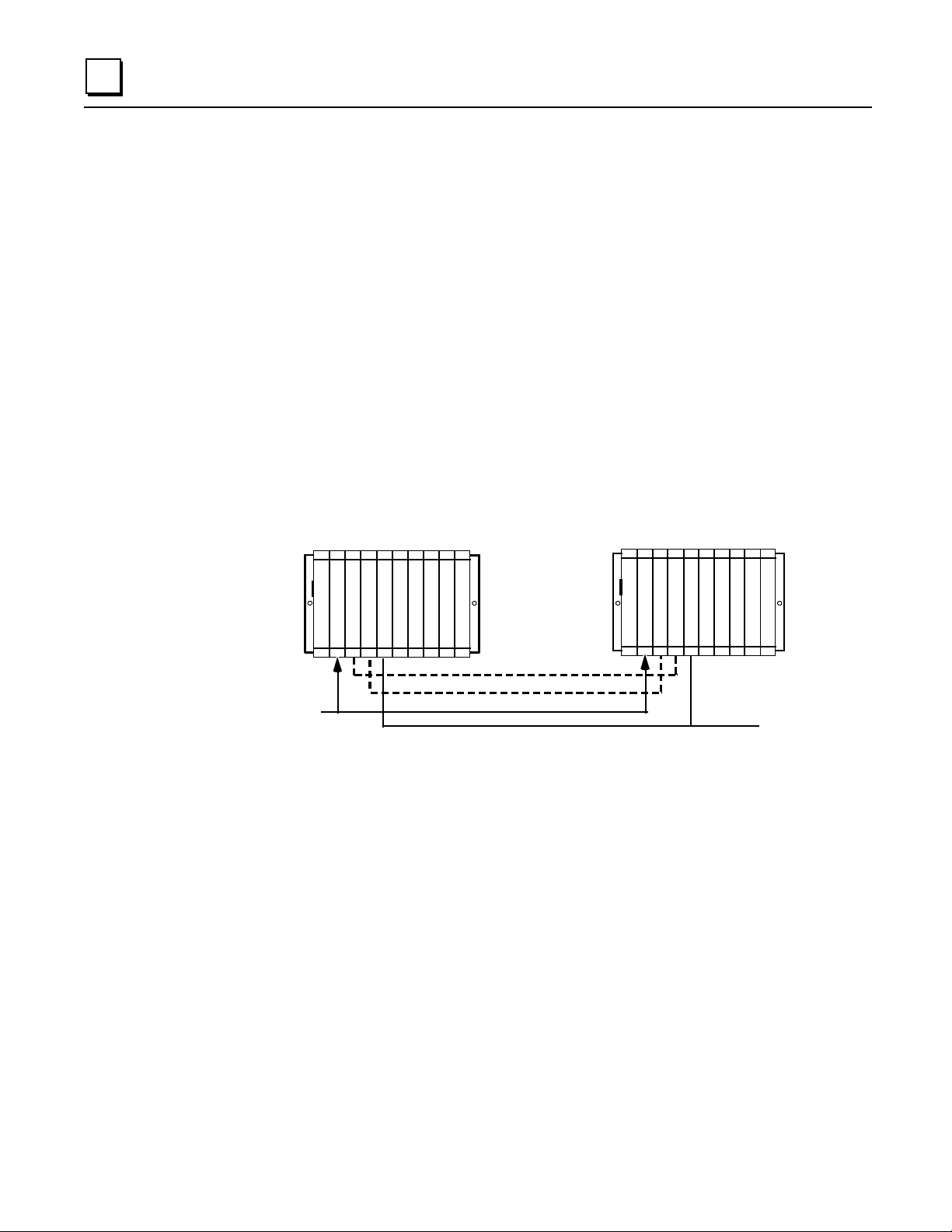
Dual Bus with Floating Master: GDB Control Strategy
This type of system uses dual buses with bus controllers in each PLC. No switchover occurs on
initial synchronization to make the Primary Unit the Active Unit. Bus Switch ing Modules (BSMs)
are required in accordance with the traditional configuration of a Dual Bus network. This option
pr ovides redundan c y of both the P L C and the I/O bus.
C
P
U
C
P
U
B
T
M
R
C
M
G
B
C
30
Secondary Unit Prima r y U ni t
31
B
L
O
C
K
B
L
O
C
K
P
S
P
S
B
T
M
R
C
M
G
B
C
B
L
O
C
K
Critical Data + Redundant
Outputs Transferred
30
G
B
C
G
B
C
31
Bus Switching Module
The Dual Bus with floating master setup is suitable if:
A.
The application requires redundancy of the PLC and I/O bus, AND
B.
The Active unit should not switch when the Primary Unit is returned to service.
Dual Bus with Floating Mast er r equires sel ecti on of the GDB contr ol stra t egy.
The GBCs must be confi g ured with the following settings
Redundant Mode = DB/RC (Dual Bus/Redundant Controlle r)
Paired GBC = INT/EXT (Internal External)
Serial Bu s Addr = 31 (Primary Unit) or 30 (Secondar y Uni t)
The I/ O block s must be con fi g u red with th e fol l owing settings:
(Hand-Held Monitor) CPU Redundancy = HOT STBY MODE*
(Hand-Held Monitor) BSM Present = YES
(Hand-Held Monitor) BSM Controller = YES or NO (depending on the block)
(Programmin g Tool) Redundancy = YE S
* Configuration as Duplex mode is also permitted; duplex default also needs to be properly
selected. . (See “Duplex CPU Redundancy” on page 1-13.)

GFK-1527A Chapter 1 Introduction 1-13
1
Duplex CPU Redundancy
Only discrete blocks (or Remote I/O Scanners with only discrete modules) can be
configured for Duplex CPU Redundancy mode. Blocks or I/O Scanners configured for
Duplex mod e receive outputs from BOTH bus controller s 30 and 31, and com p are them.
If devices 30 and 31 a gree on an outp ut state, the ou tput goes to th a t s tate. If devices 30
and 31 send different states for an output, the block or I/O Scanner defaults that output
to its pre- s elected Dup lex Defaul t State. F or ex ample:
Commanded State
from D evic e
Number 31
Commanded State
from D evic e
Number 30
Duplex Default
State in the Block
or I/O Scanner
Actual Output
State
On On Don’ Care On
Off On Off Off
Off Off Don’t Care Off
On Off On On
If either device 30 or 31 stop s sending outputs to the block or I/O Sc a nner, outputs wi ll be direct ly
controlled by the remaining device.
Online Programming
On-line changes to the application program are permitted in both the active unit and the backup
unit. The programming device mu s t be connected to the system in which changes are to be made
in order to make any on-line changes. Note that all precautions regarding power source and
groun d ing for connecting the programming device mu st be followed in accordance with
instructions in the
Series 90-70 Programmable Controller Installation Manual
, GFK-0262.
A connect ion and di s connecti on of t he parallel programm er cable should only be ma d e wi th the
programmer proper ly grounded, and programming software proper l y booted up and in OFF-LINE
mode. For more information, refer to the
Series 90-70 Programmable Controller Installation
Manual
, GFK-0262.
On-Line Repair
An Enhanced Hot Standby CPU Redundancy system permits online repair of failed components
with out disrupt ing the process under control. Control stat u s of both the Prim ary and the Secondary
units can be monitored by the LEDs on the Redundancy Communications Module in each system.
When a component of the active unit fails, control switches to the backup unit. The failed
component can then be replaced after first removing power from the rack in which it is installed.
After r eplacement of the failed compon en t and return ing power to the rack, th e ba ck u p unit
resynchronizes with the currently active unit. The unit that had failed, which was previously the
active unit, determines its role in the system based on configured control strategy.
Online repair is described in more detail in chapter 5.

GFK-1527A 2-1
System Components
This chapter describes the hardware components for an Enhanced Hot Standby CPU Redundancy
system.
System Rack s
Redundancy CPU
Redundancy Communications Module
Bus Transmitter Module
Bus Receiver Module
Genius Bus Controller
For Installation Instructions
For detailed installation instructions for the Series 90-70 PLC, refer to GFK-0262, the Series 90-70
Programmable Controller Ins tal lation Manual.
System Racks
The following Series 90-70 I/O racks may be used in a Hot Standby CPU Redundancy System:
IC697CHS750, 5-slot rear mount - standard rack
IC697CHS790, 9-slot rear mount - standard rack
IC697CHS791, 9-slot front mount - standard rack
IC697CHS770, redunda nt rack - rear mount
IC697CHS771, redundant rack - fro nt mount
Use of Series 90-70 VME Integrator racks (IC697CHS782 and IC697CHS783) in a Hot Standby
CPU Redundancy System is not supported.
2
Chapter
2
2-2 Series 90™-70 Enhanced Hot Standby CPU Redundancy User's Guide
–
May 2000 GFK-1527A
2
Redundanc y CPU
The redundancy CPUs have been designed specifically for Series 90-70 Hot Standby CPU
Redundancy applications.
Features
The Enhanced Hot Standby CPU supports floating point calculations, offers remote programmer
keyswitch memory protection, and has seven status LEDs. Operation of the CPU may be
controlled by the three-position RUN/STOP switch on the module, or remotely by an attached
programmer. Program and configuration data can be locked through software passwords or
manually by the memory protect keyswitch. When the key is in the protected position, a
progr ammer connected to th e Bus Tr ansmitt er M odu le can only change progr am and config uration
data.
In a Hot Standby CPU Redundancy system, one CPU is configured as the Primary CPU and the
other as the Secondary CPU. The Primary unit an d the Secondary unit must each have a
Redundancy CPU installed in slot 1 of rack 0.
C
P
U
C
P
U
B
T
M
R
C
M
G
B
C
30
Secondary Unit Primary Unit
31
P
S
P
S
B
T
M
R
C
M
G
B
C
Genius Bus
CGR935
Redundanc
y
C
ommunications Link
Redundanc
y
C
ommunications Link
CGR772
in these slots
or
Not all features of other Series 90-70 CPUs are available in redundancy models. See chapter 4 for
details.

GFK-1527A Chapter 2 System Components 2-3
2
CPU Architecture
The CGR772 and CGR935 have an 80486DX4 microprocessor, on-board memory, and a dedicated
VLSI proce s sor for per f orming Boolean opera tions. The CG R772 and CGR935 interface to serial
ports and the system bus. The microprocessor provides all fundamental sweep and operation
control, plu s e xecut ion of non- Boolean func tions. Bool ean functi ons ar e ha ndled by the dedi c ated
VLSI, Boolean Coprocessor (BCP).
Model
Speed
(MHz)
Processor
Input
Points
Output
Points
Expansion
Memory
Floating
Point Math
CGR772 96 80486DX4 2048 2048 512K Bytes Yes
CGR935 96 80486DX4 12288 12288 1 Megabyte Yes
Expansion Memory Board
Program and data memory are provided by an attached expansion memory board with 512K Bytes
of user memory for CGR772 and 1 Megabyte of user memory for CGR935. The expansion
mem ory board pr ovides RA M memory for program and data stor age. Error check ing is provid e d by
a CPU ch eck sum routine. Logic progr am memory is continual ly error- ch eck ed by the CPU a s a
background task. Memory pari ty errors ar e reported to the microprocessor when they occur.
The RAM memory on the expansion memory board is backed-up by the Lithium battery mounted
on the CPU module.
Watchdog Timer
The CPU provides a watchdog timer to catch certain failure conditions. The value of this timer can
be set from 10 milliseconds to 1000 milliseconds. The default is 200 milliseconds. The watchdog
timer resets at the beginning of each sweep. The watchdog timer should be set to allow for the
expected scan
plus
two fail wait times.
2-4 Series 90™-70 Enhanced Hot Standby CPU Redundancy User's Guide
–
May 2000 GFK-1527A
2
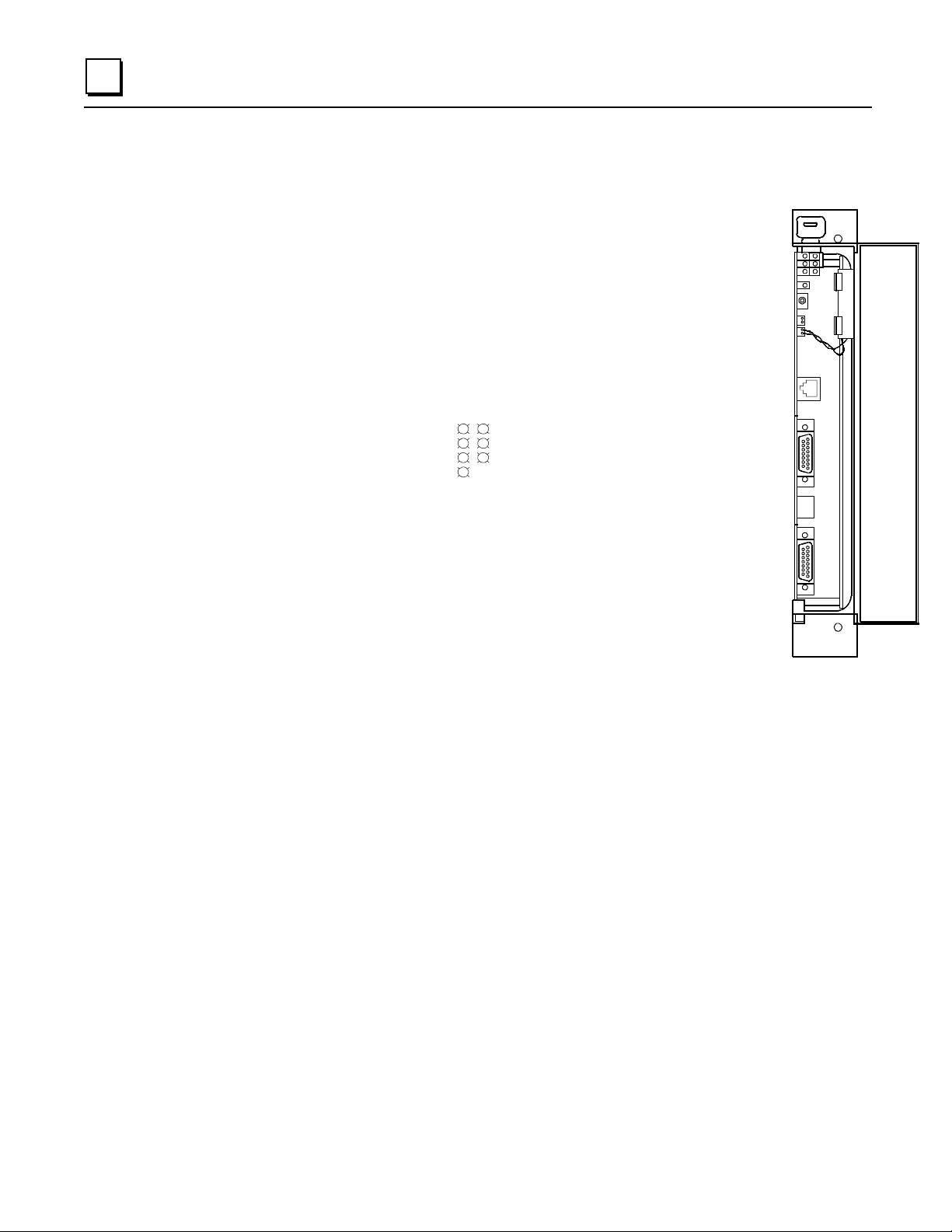
CPU Features
Memory Pro tect Keyswitch
The Memory Protect keyswitch can be used to manually
lock program and configuration data from access by a
remote programmer (serial or Ethernet). When the key is
in the ON p os ition , program and con figurati on data
can
only be changed
by a programmer connected to the Bu s
Tran sm itter Module.
CPU LEDs
OK:
The OK LED is
ON
when the CPU is functioning properly. The
OK LED blinks when the CPU executes power-up diagnostics, when
the remote unit is powered-up, or if the system has failed. If the system
has failed and the OK LED is blinking, the CPU can still communicate
with the programm er (the CPU cannot commun i cate with the
programmer during power-up diagnostics). If the OK LED is OFF, the
system has failed and the CPU cannot communicate with the
programmer.
RUN:
This LED is
ON when the CPU is in the RUN/ENABLE or RUN/DISABLE mode. It is
OFF when the CPU is in STOP mode.
ENabled
:
This LED is ON when outputs are enabled and OFF when outputs are disabled.
MEMory PROTECT:
This LED indicates the status of the memory protect keyswitch. It is ON
when the keyswitch is in the ON position. It is OFF when the keyswitch is in the OFF position.
P1, P2, P3:
LED blinks intermittently when there is serial communications on the indicated serial
port (Port 1, Port 2, or Port 3).
Batter y Co nnector s
There are two identical battery connectors. The battery currently installed can remain connected
while a new battery is being installed, minimizing the risk of data loss. A Low Battery Warning
occurs when the battery needs replacement.
When the CPU is in storage, the battery can be disconnected if there is no application program
stored in memory. If a program is stor ed in memory, the battery sh ould not be disconnect ed , or the
data will be lost.
OK
RUN
EN
MEM PROTECT
P1
P2
P3
Y
R
E
B
A
T
T
Battery
Connectors
Memory
Protect
Keyswitch
LEDs
CPU Mode
Switch
Port 1
RS-232
Port 2
RS-485
Port 3
RS-422/485

GFK-1527A Chapter 2 System Components 2-5
2
CPU Mode Switch
The CPU Mode switch selects the op eratin g mode o f the CPU:
RUN/ENABLED , RUN/DIS ABLED
,
or
STOP
. The CPU mode can also be controlled from the programmer. However, the CPU Mode
switch position restricts the ability of the programmer to put the CPU into certain modes, as shown
in the fo llo wing table.
CPU Mode Switch Position Allowable Programmer
Mode Command
Run/Outputs Enabled Run/Enabled
Run/Disabled
Stop
Run/Outputs Disabled Run/Disabled
Stop
Stop Stop
Run/Outputs Enabled Mode
In this mode, the CPU executes all portions of the sweep normally.
Run/Outputs Disabled Mode
In this mode, the CPU executes all portions of the sweep normally, but physical outputs are held in
their default state and remain unchanged. Refer to Chapter 4 for important information about
Run/Disabled mode in a Hot Standby CPU Redundancy system.
Stop Mode
In Stop mod e, the CPU commu n icates with the programmer and th e d evices conn ected to th e ser ial
port , com municat es with other communications modul es such as the eth ernet modul e, and recover s
fault ed modules. Values in the I/ O ta bl es can be changed using the programm ing comput er .
The STOP/IOSCAN mode
is not a valid mode
in a redun dancy system. Refer to Chap ter 4 for
detailed information.
Port 1
The RJ-11 connector provides an RS-232 compatible serial port.
Port 2
The 15-pin D-connector is an RS-485 compatible serial port.
Port 3
The 15-pin D-connector at the bottom of the module provides an RS-422/RS-485 serial port. For
applications requiring RS-232 communications, an RS-232 to RS-422 converter (IC690ACC900)
or RS-232 to RS422 miniconverter (IC690ACC901) is available.
Note
An RS-422 Isolated Repeater/RS-232 Converter (IC655CCM590) is available for
applications requiring ground isolation where a common ground cannot be
established between components.
Loading...