


ROOM |
CONDITIONER |
|
|
||
|
AIR |
|
SAFETY INFORMATION . . . . . . . . .3
USING THE AIR CONDITIONER
Controls . . . . . . . . . . . . . . . . . . . . . . . . . . . . . .4
Remote Control . . . . . . . . . . . . . . . . . . . . . . .5
Cool Mode . . . . . . . . . . . . . . . . . . . . . . . . . . . .5
ECO Mode . . . . . . . . . . . . . . . . . . . . . . . . . . . .5
Air Direction . . . . . . . . . . . . . . . . . . . . . . . . . .6
CARE AND CLEANING
Grille and Case . . . . . . . . . . . . . . . . . . . . . . . .7
Air Filter. . . . . . . . . . . . . . . . . . . . . . . . . . . . . .7
Outdoor Coils . . . . . . . . . . . . . . . . . . . . . . . . .7
Install Batteries in Remote . . . . . . . . . . . . . .7
INSTALLATION INSTRUCTIONS
Before you begin . . . . . . . . . . . . . . . . . . . . . .8 Electrical Requirements . . . . . . . . . . . . . . . .8 Parts Included . . . . . . . . . . . . . . . . . . . . . . . . .9 Window Requirements . . . . . . . . . . . . . . . . 10 Prepare the Air Conditioner . . . . . . . . . . . . 10 Install the Air Conditioner. . . . . . . . . . . . . . 13
TROUBLESHOOTING TIPS. . . . . . 16
Normal Operating Sounds . . . . . . . . . . . . . 16
WIFI SETUP . . . . . . . . . . . . . . . . . . . . . . 17
CONSUMER SUPPORT
Limited Warranty . . . . . . . . . . . . . . . . . . . . . 19
Consumer Support . . . . . . . . . . . . . . . . . . . 20
Before you begin
Record the GE module number and password for wifi setup. To locate this information, see page 17.
GE Module Number #____________
Password #____________________
Write the model and serial numbers here:
Model #_________________
Serial # _________________
You can find the rating label on the side of the air conditioner.
OWNER’S MANUAL & INSTALLATION INSTRUCTIONS
AHC18
AEC18
GE is a trademark of the General Electric Company. Manufactured under trademark license.
49-5000090 09-18 GEA

THANK YOU FOR MAKING GE APPLIANCES A PART OF YOUR HOME.
Whether you grew up with GE Appliances, or this is your first, we’re happy to have you in the family.
We take pride in the craftsmanship, innovation and design that goes into every GE Appliances product, and we think you will too. Among other things, registration of your appliance ensures that we can deliver important product information and warranty details when you need them.
Register your GE appliance now online. Helpful websites and phone numbers are available in the Consumer Support section of this Owner’s Manual. You may also mail in the pre-printed registration card included in the packing material.
2 |
|
49-5000090 |

IMPORTANT SAFETY INFORMATION
READ ALL INSTRUCTIONS BEFORE USING THE APPLIANCE
 WARNING For your safety, the information in this manual must be followed to minimize the risk of fire, electric shock or personal injury.
Ŷ 8VH WKLV DSSOLDQFH RQO\ IRU LWV LQWHQGHG SXUSRVH DV described in this Owner’s Manual.
Ŷ This air conditioner must be properly installed in accordance with the Installation Instructions before it is used.
Ŷ Never unplug your air conditioner by pulling on the power cord. Always grip plug firmly and pull straight out from the receptacle.
Ŷ Replace immediately all electric service cords that have become frayed or otherwise damaged. A damaged power supply cord must be replaced with a new power supply cord obtained from the manufacturer and not repaired. Do not use a cord that shows cracks or abrasion damage along its length or at either the plug or connector end.
Ŷ Turn the unit OFF and unplug your air conditioner before cleaning.
Ŷ *( $SSOLDQFHV GRHV QRW VXSSRUW DQ\ VHUYLFLQJ RI WKH air conditioner. We strongly recommend that you do not attempt to service the air conditioner yourself.
Ŷ For your safety…do not store or use combustible materials, gasoline or other flammable vapors or liquids in the vicinity of this or any other appliance.
Ŷ All air conditioners contain refrigerants, which under federal law must be removed prior to product disposal. If you are getting rid of an old product with refrigerants, check with the company handling disposal about what to do.
Ŷ If the receptacle does not match the plug, the receptacle must be changed out by a qualified electrician.
Ŷ These R410A air conditioning systems require contractors and technicians to use tools, equipment and safety standards approved for use with this refrigerant. DO NOT use equipment certified for R22 refrigerant only.

 WARNING USE OF EXTENSION CORDS
RISK OF FIRE. Could cause serious injury or death. |
Ŷ '2 127 XVH VXUJH SURWHFWRUV RU PXOWL RXWOHW DGDSWRUV |
Ŷ '2 127 XVH DQ H[WHQVLRQ FRUG ZLWK WKLV :LQGRZ $LU |
with this Window Air Conditioner. |
|
|
Conditioner. |
|
HOW TO CONNECT ELECTRICITY
Do not, under any circumstances, cut or remove the third (ground) prong from the power cord. For personal safety, this appliance must be properly grounded.
DO NOT use an adapter plug with this appliance.
The power cord of this appliance is equipped with a 3-prong (grounding) plug which mates with a standard 3-prong (grounding) wall outlet to minimize the possibility of electric shock hazard from this appliance.
Power cord includes a current interrupter device. A test and reset button is provided on the plug case. The device should be tested on a periodic basis by first pressing the TEST button and then the RESET button while plugged into the outlet. If the TEST button does not trip or if the RESET button will not stay engaged, discontinue use of the air conditioner and contact a qualified service technician.
Have the wall outlet and circuit checked by a qualified electrician to make sure the outlet is properly grounded.
Where a 2-prong wall outlet is encountered, it is your personal responsibility and obligation to have it replaced with a properly grounded 3-prong wall outlet.
The air conditioner should always be plugged into its own individual electrical outlet which has a voltage rating that matches the rating plate.
This provides the best performance and also prevents overloading house wiring circuits which could cause a fire hazard from overheated wires.
See the Installation Instructions, Electrical Requirements section for specific electrical connection requirements.
INFORMATION SAFETY
49-5000090 |
READ AND SAVE THESE INSTRUCTIONS |
3 |
|
USING THE AIR CONDITIONER
IMPORTANT SAFETY INFORMATION
READ ALL INSTRUCTIONS BEFORE USING THE APPLIANCE
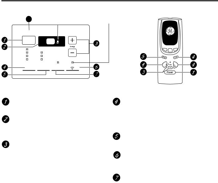
Controls
Features and appearance will vary.
Lights below the touch pads on the air conditioner control panel indicate the selected settings.
8 |
Light indicates the unit is in |
Light indicates |
|
the temperature set mode. |
WiFi connection |
Power |
|
|
|
Auto |
|
|
|
High |
Cool |
|
|
Med |
Fan |
|
|
Low |
Eco |
|
|
Fan |
Mode |
Reset |
WiFi |
Filter |
|
||
|
|
|
Mode select
Fan speed Decrease
Temperature set Increase and Decrease
Fan  Fan
Fan
Auto Fan on
Fan speed Increase
8QLW SRZHU on/off
Air Conditioner Controls
Power Pad
Turns air conditioner on and off. When turned on, the display will show the room temperature.
Display
Shows the room temperature or time remaining on the Delay timer. Shows the Set temperature while setting the temperature in Heat, Cool or ECO modes.
Temp Increase + /Decrease – Pads
8VH WR VHW WHPSHUDWXUH ZKHQ LQ Heat, Cool or ECO mode. The Set light will turn on while setting.
Delay Increase + /Decrease – Pads
Each touch of the Increase + / Decrease - pads on the unit or the Increase + / Decrease – pads on the remote control will set the delay time when using the Delay 1–24hr timer. The Set light will turn on while setting.
Remote Control
Fan Speed Pads
8VH WR VHW WKH IDQ VSHHG WR Low, Med, High or Auto on the unit. NOTE: On the remote control, use the fan speed Increase + / Decrease – pads to set the fan speeds to Low, Med or High 8VH WKH Auto pad to turn Auto fan on.
Mode Pad
8VH WR VHW WKH DLU FRQGLWLRQHU WR Heat, Cool, ECO or
Fan Only mode.
WiFI
Enables connection of the air conditioner to the home WiFi. Download App for details at GEAppliances.com/ connect.
Filter Reset Pad
LED will turn on when fan has accumulated 250 hours of run time as a reminder to clean filter. Press Reset Filter to turn off the LED and reset the accumulated run time.
Note: The default temperature reading on the display is degree Fahrenheit ( °F). To change the display to degree Celcius (°C), press the Temp Increase + and Temp Decrease - buttons together and hold for 3 seconds. Repeat the process to change back to degree Fahrenheit (°F)
4 |
49-5000090 |
Using the Air Conditioner
Control Display On and Off
To reduce brightness during sleeping hours, this air conditioner control display has an automatic off feature where the control display will turn off completely after 5 minutes of inactivity. To
illuminate the control interface, press any button on the control display or remote control. The control display will illuminate all previously illuminated LED’s. The control interface will now respond to any prescribed button press after it is illuminated.
Press and hold the FAN+MODE buttons simultaneously to toggle this feature ON or OFF. The LED’s will now stay ON anytime the unit is ON.
Do Not Operate in Freezing Outdoor Conditions
 Control sound on/off
This air conditioner will make a beep when the buttons on the control are pushed or if the unit receives a command from the mobile app or remote control. To silence these beeps, simultaneously press the FAN and “-” buttons for 3 seconds. Press these buttons again to toggle the sound back on.
This cool-only air conditioner was not designed for freezing outdoor conditions. It must not be used when the outdoor temperature is below freezing (32°F).
Remote Control
Ŷ To ensure proper operation, aim the remote control at the |
Ŷ 0DNH VXUH EDWWHULHV DUH IUHVK DQG LQVWDOOHG FRUUHFWO\ DV |
signal receiver on the air conditioner. |
indicated on the remote control. |
Ŷ 0DNH VXUH QRWKLQJ LV EHWZHHQ WKH DLU FRQGLWLRQHU DQG |
Ŷ 5HPRWH FRQWDLQV D PDJQHW DOORZLQJ LW WR DWWDFK WR PHWDO |
the remote control that could block the signal. |
surfaces. |
Ŷ The remote control signal has a range of up to 20 feet. |
|
Cool Mode
8VH WKH &RRO PRGH DW /RZ 0HG +LJK RU $XWR )DQ
6SHHG IRU FRROLQJ 8VH WKH 7HPSHUDWXUH ,QFUHDVH
Decrease - pads to set the desired temperature between 64°F and 86°F in 1°F increments.
An electronic thermostat is used to maintain the room temperature. The compressor will cycle on and off to keep the room at the set level of comfort. Set the thermostat at a lower number and the indoor air will
become cooler. Set the thermostat at a higher number and the indoor air will become warmer.
NOTE: If the air conditioner is off and is then turned on while set to a Cool setting or if turned from a fan setting
to a Cool VHWWLQJ LW PD\ WDNH DSSUR[LPDWHO\ PLQXWHV IRU the compressor to start and cooling to begin.
Cooling Descriptions
For Normal Cooling—Select the Cool mode and
High or Med fan with a middle set temperature.
For Maximum Cooling—Select the Cool mode and High fan with a lower set temperature.
For Quieter and Nighttime Cooling—Select the
Cool mode and Low fan with a middle set temperature.
ECO Mode
This mode optimizes the cooling power of your air conditioner, thereby saving you energy. Once the set point temperature has been reached, the fan will cycle off to save energy. The fan will cycle back on periodically to insure all cooling capacity in the system is used. This mode is the default mode for the unit. Each time the unit is powered off, it will restart in ECO mode ON. This includes Delay timer mode. The first time the unit is turned on, the settings will be 70° and Low fan. You can adjust the fan speed and temperature to your personal comfort.
ON—The fan will cycle on and off with the compressor. This may result in wider variations of room temperature and humidity. NOTE: the fan may continue to run
for a short time or may pulse intermittently after the compressor cycles off to sample the room air.
OFF—The fan runs all the time, while the compressor cycles on and off.
CONDITIONER AIR THE USING
49-5000090 |
5 |
USING THE AIR CONDITIONER
Using the Air Conditioner
Fan Only Mode
8VH WKH )DQ 2QO\ 0RGH DW /RZ 0HG RU +LJK IDQ VSHHG |
NOTE: Auto Fan Speed cannot be used when in the |
to provide air circulation and filtering without cooling. |
Fan Only Mode. |
Since fan-only settings do not provide cooling, a Set |
|
temperature cannot be entered. The room temperature |
|
will appear in the display. |
|
|
|
Auto Fan Mode |
|
Set to Auto fan speed for the fan speed to automatically set to the speed needed to provide optimum comfort settings with the set temperature.
If the room needs more cooling, the fan speed will automatically increase. If the room needs less cooling, the fan speed will automatically decrease.
NOTE: Auto Fan Speed cannot be used when in the Fan Only Mode.
Control Display On and Off
To reduce brightness during sleeping hours, this air conditioner control display has an automatic off feature where the control display will turn off completely
after 2 minute of inactivity. To illuminate the control interface, press any button on the control display or remote control. The control display will illuminate all previously illuminated LED’s. The control interface will now respond to any prescribed button press after it is illuminated.
Power Outage Recovery Feature
In the case of a power outage or interruption, the unit will automatically restart in the settings last used after the power is restored. If the Delay 1–24hr feature was set, it will resume countdown. You may need to set a new time if desired.
Air Direction
8VH WKH OHYHU WR DGMXVW WKH DLU GLUHFWLRQ OHIW DQG ULJKW only.
6 |
49-5000090 |

Care and Cleaning
Grille and Case
Turn the air conditioner off and remove the plug from the |
To clean, use water and a mild detergent. Do not use |
wall outlet before cleaning. |
bleach or abrasives. |
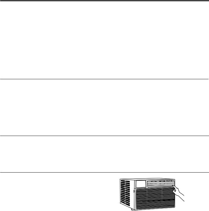
Air Filter
The air filter behind the front grille should be checked and cleaned at least every 30 days or
more often if necessary.
To remove:
Open the inlet grille by pulling downward on the tabs at the top upper corners of the inlet grille until the grille is in a 45º position. Remove the filter.
Clean the filter with warm, soapy water. Rinse and let the filter dry before replacing it. Do not clean the filter in a dishwasher.
DO NOT operate the air conditioner without a filter
because dirt and lint will clog it and CAUTION reduce performance.
Tab |
Tab |
Outdoor Coils
The coils on the outdoor side of the air conditioner should be checked regularly. If they are clogged with dirt or soot, they may be professionally cleaned.
How to Insert the Battery in the Remote Control
1.Remove the battery cover by sliding it according to the arrow direction.
2.Insert new batteries, making sure that the (+) and (–) of battery are installed correctly.
3.Reattach the cover by sliding it back into position.
NOTES:
Ŷ 8VH ³$$$´ YROW EDWWHULHV 'R QRW XVH rechargeable batteries.
Ŷ Remove the batteries from the remote control if the system is not going to be used for a long time.
Ŷ 'R QRW PL[ ROG DQG QHZ EDWWHULHV 'R QRW PL[ VWDQGDUG
(carbon-zinc) or rechargeable (ni-cad, ni-mh, etc) batteries.
CLEANING AND CARE
49-5000090 |
7 |

INSTALLATION INSTRUCTIONS
Installation Instructions
Questions? Call 800.GE.CARES (800.432.2737) or Visit our Website at: GEAppliances.com
BEFORE YOU BEGIN
Read these instructions completely and carefully.
• IMPORTANT – Save these
instructions for local inspector’s use.
• IMPORTANT – Observe all
governing codes and ordinances.
•Note to Installer – Be sure to leave these instructions with the Consumer.
•Note to Consumer – Keep these instructions for future reference.
•Skill level – Installation of this appliance requires basic mechanical skills.
•Completion time ± $SSUR[LPDWHO\ KRXU
•We recommend that two people install this product.
•Proper installation is the responsibility of the installer.
•Product failure due to improper installation is not covered under the Warranty.
<RX 0867 XVH DOO VXSSOLHG SDUWV DQG XVH SURSHU installation procedures as described in these instructions when installing this air conditioner.
ELECTRICAL REQUIREMENTS
Some models require a 115/120-volt AC, 60-Hz grounded outlet protected with a 15-amp time-delay fuse or circuit breaker.
The 3-prong grounding plug minimizes the possibility of electric shock hazard. If the wall outlet you plan to use is only a 2-prong outlet, it is your responsibility to have it replaced with a properly grounded 3-prong wall outlet.
Some models require 230/208-volt AC, protected with a time-delay fuse or circuit
breaker. These models should be installed on their own single branch circuit for best
performance and to prevent overloading house or apartment wiring circuits, which could cause a possible fire hazard from overheating wires.

 CAUTION
Do not, under any circumstances, cut or remove the third (ground) prong from the power cord.
Do not change the plug on the power cord of this air conditioner.
Aluminum house wiring may present special problems—consult a qualified electrician.
TOOLS YOU WILL NEED |
|
Phillips head screwdriver |
|
|
Flat-blade screwdriver |
Pencil |
Ruler or tape measure |
Level |
Scissors or knife |
Power cord includes a current interrupter device. A test and reset button is provided on the plug case. The device should be tested on a periodic basis by first pressing the TEST button and then the RESET button while plugged into the outlet. If the TEST button does not trip or if the RESET button will not stay engaged, discontinue use of the
air conditioner and contact a qualified service technician.
8 |
49-5000090 |

Installation Instructions
PARTS INCLUDED |
|
|
|
|
(Appearance may vary) |
|
|
|
|
|
|
|
Accordion panel |
|
|
|
Window sill and |
seal (2) |
|
|
|
|
|
|
|
|
sash seal (2) |
|
|
|
|
Foam top window |
|
|
Top rail gasket (1) |
|
gasket (1) |
|
|
|
|
|
|
|
|
|
Left |
|
|
Top |
|
accordion |
|
Right |
mounting |
|
panel |
|
accordion |
rail |
|
|
|
panel |
|
|
|
|
Foam |
|
|
|
|
Insulation |
|
|
|
|
(2) |
Side rail (2) |
|
|
|
|
|
|
Sill angle |
Window |
|
V-supports (2) |
locking |
|
||
bracket (2) |
|
|||
|
|
bracket (2) |
|
|
|
|
|
|
|
Type A |
Type B |
Type C |
|
|
screws (10) |
screws (2) |
screws (4) |
Type E bolt with |
Type F bolt with |
|
|
|
nut (4) |
nut (2) |
49-5000090 |
|
|
|
9 |
INSTRUCTIONS INSTALLATION

INSTALLATION INSTRUCTIONS
Installation Instructions
1.WINDOW REQUIREMENTS
•These instructions are for a standard double-hung window. You will need to modify them for other types of windows.
•The air conditioner can be installed without the accordion panels if needed to fit in a narrow window. See the window opening dimensions.
•All supporting parts must be secured to firm wood, masonry or metal.
•The electrical outlet must be within reach of the power cord.
18-1/2”
26” - 41”
(With accordion panels)
2. STORM WINDOW REQUIREMENTS
A storm window frame will not allow the air conditioner to tilt toward the outside, and will keep it from draining properly. To adjust for this, attach a piece of wood to the sill.
WOOD PIECES WIDTH: 2Ǝ
LENGTH: Long enough to fit inside the window frame.
THICKNESS: To determine the thickness, place
D SLHFH RI ZRRG RQ WKH VLOO WR PDNH LW Ǝ KLJKHU than the top of the storm window frame or the vinyl frame.
Attach securely with nails or screws provided by the installer.
Ǝ KLJKHU  than storm window
frame
Storm window frame
Ǝ KLJKHU than vinyl frame
(on some windows)
Wood
Sill
Vinyl frame
3.PREPARE THE AIR CONDITIONER
A. Pull down the front panel and remove the filter. Remove the front panel by lifting up at an angle.
B. Remove the four front screws. Save them for reinstalling the front housing.
C. Grasp the lower corners of the grille while pressing in on the case sides with your finger tips. Pull out to release and lift it up.
NOTE: Do not pull the bottom edge toward you
PRUH WKDQ Ǝ RU \RX PD\ GDPDJH WKH WDEV RI the grille.
D. When the front grille is removed the control panel will still be attached by a harness. Turn the grille around so you can see the back side of the grille. Remove the 2 screws to separate the control panel housing from the grille. NOTE: Be sure to save these screws. You will need them later in the installation.
Remove Screws
10 |
49-5000090 |

Installation Instructions
3.PREPARE THE AIR CONDITIONER (continues)
E.Remove the ground screw from the left side of the case. Keep it in a safe location. NOTE: Be sure to save this screw. You will need them later in the installation.
F.Slide the air conditioner from the case by gripping the base pan handle and pulling forward while bracing the case. Do not pull or lift on the foam discharge area.
Do not pull or lift in this area— damage to the unit may result
FRONT
4. PREPARE THE CASE
A. Attach the top rail gasket to the bottom of the top rail.
B. Install the top mounting rail with 4 type A screws from the inside of the case. Press firmly to drive the screws into the gasket and through the top mounting rail.
Top mounting rail
4.PREPARE THE CASE
C. Slide each side retainer onto the edge of each according panel. The figure shows the orientation of each accordion panel and side retainer assembly relative to the case from a top view of the unit.
SIDE RETAINER
WINDOW FILLER PANEL
SIDE RETAINER
WINDOW FILLER PANEL
D. Slide the left and right accordion panels into the top and bottom mounting rails.
Top left |
|
|
|
|
|
|
|
|
|
Top mounting rail |
Top right |
|||||||||||||||||
|
|
|
|
|
|
|
|
|
|
|
|
|
|
|
|
|
|
|
|
|||||||||
|
|
|
|
|
|
|
|
|
|
|
|
|
|
|
|
|
|
|
|
|
|
|
|
|
|
|
|
|
|
|
|
|
|
|
|
|
|
|
|
|
|
|
|
|
|
|
|
|
|
|
|
|
|
|
|
|
|
|
|
|
|
|
|
|
|
|
|
|
|
|
|
|
|
|
|
|
|
|
|
|
|
|
|
|
|
|
|
|
|
|
|
|
|
|
|
|
|
|
|
|
|
|
|
|
|
|
|
|
|
|
|
|
|
|
|
Bottom mounting rail
E.Attach the side retainers to the case using 6 type A screws.
INSTRUCTIONS INSTALLATION
49-5000090 |
11 |

INSTALLATION INSTRUCTIONS
Installation Instructions
5.PREPARE THE WINDOW AND INSTALL THE CASE
A.Cut the window sash seal to the proper length. Peel off the backing and attach the seal to the underside of the window sash.
B. Open the window and mark the center of the window sill.
C. Carefully slide the case into the window and center the case. Lower the window behind the top mounting rail. Pull the bottom of the case forward so that the bottom mounting rail is tight against the back of the window stool. Mount the case to the window sill using 2 type B screws. Drill pilot holes, if necessary.
2 type B screws
Stool
D. Assemble the V-support and V-support bracket with Type F nut and bolt.
|
Type E bolt |
|
and nut |
Left |
|
Sill angle |
Right |
bracket |
|
V-support |
|
Type F bolt |
|
and nut |
|
5.PREPARE THE WINDOW AND INSTALL THE CASE (continues)
E. Position the V-supports
on the case bottom so |
|
|
that they will be near the |
|
|
outside wall. Attach a |
|
|
V-support to each side of the |
|
|
bottom of the case with Type |
V-support |
|
E bolts, 2 for each support. |
||
|
F. Adjust sill angle brackets to rest on sill.
 Sill
Sill


 Bracket
G. ([WHQG WKH OHIW DQG ULJKW DFFRUGLRQ SDQHOV
to the vertical window sashes. Drill pilot holes and attach the top corners with 2 type C screws.
Type C |
Type C |
screw |
screw |
12 |
49-5000090 |
 Loading...