


GEAppliances.com
Air Conditioners
Room
Safety Instructions. . . . . . . . . . . . . 2, 3
Operating Instructions
Controls . . . . . . . . . . . . . . . . . . . . . . . . . . . 4–6
Care and Cleaning
Air Filter . . . . . . . . . . . . . . . . . . . . . . . . . . . . . .6
Outdoor Coils . . . . . . . . . . . . . . . . . . . . . . . . .6
Installation Instructions. . . . . . 7–13
Troubleshooting Tips . . . . . . . . . . . .14
Normal Operating Sounds . . . . . . . . . . . .14
Consumer Support
Consumer Support . . . . . . . . . . Back Cover Ownership Registration for
Customers in Canada only. . . . . . . . 15, 16 Warranty for Customers
in Canada . . . . . . . . . . . . . . . . . . . . . . . . . . .18 Warranty for Customers
in the U.S.A. . . . . . . . . . . . . . . . . . . . . . . . . . .17
Write the model and serial numbers here:
Model # _________________________
Serial # __________________________
Find these numbers on a label on the side of the air conditioner.
In Canada, contact us at:
www.GEAppliances.ca
Owner’s Manual and
Installation Instructions
AEE24
Climatiseur
Manuel d’utilisation et instructions d’installation
La section française commence à la page 19
Acondicionador
de aire
Manual del propietario y instrucciones de instalación
La sección en español empieza en la página 37
49-7667-2 10-12 GE
IMPORTANT SAFETY INFORMATION.
READ ALL INSTRUCTIONS BEFORE USING.
 WARNING!
For your safety, the information in this manual must be followed to minimize the risk of fire, electric shock or personal injury.
SAFETY PRECAUTIONS
Use this appliance only for its intended purpose as described in this Owner’s Manual.
This air conditioner must be properly installed in accordance with the Installation Instructions before it is used.
Never unplug your air conditioner by pulling on the power cord. Always grip plug firmly and pull straight out from the receptacle.
Replace immediately all electric service cords that have become frayed or otherwise damaged. A damaged power supply cord must be replaced with a new power supply cord obtained from the manufacturer and not repaired. Do not use a cord that shows cracks or abrasion damage along its length or at either the plug or connector end.
Turn the unit OFF and unplug your air conditioner before cleaning.
GE does not support any servicing of the air conditioner. We strongly recommend that you do not attempt to service the air conditioner yourself.
For your safety…do not store or use combustible materials, gasoline or other flammable vapors or liquids in the vicinity of this or any other appliance.
All air conditioners contain refrigerants, which under federal law must be removed prior to product disposal. If you are getting rid of an old product with refrigerants, check with the company handling disposal about what to do.
If the receptacle does not match the plug, the receptacle must be changed out by a qualified electrician.
These R410A air conditioning systems require contractors and technicians to use tools, equipment and safety standards approved for use with this refrigerant.
DO NOT use equipment certified for R22 refrigerant only.
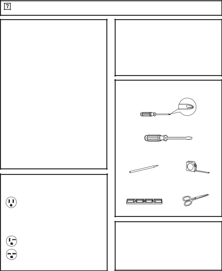
HOW TO CONNECT ELECTRICITY
Do not, under any circumstances, cut or remove the third (ground) prong from the power cord.
For personal safety, this appliance must be properly grounded.
|
DO NOT use an adapter plug with this appliance. |
|
The power cord of this appliance is equipped |
|
with a 3-prong (grounding) plug which mates |
|
with a standard 3-prong (grounding) wall outlet |
|
to minimize the possibility of electric shock |
|
hazard from this appliance. |
|
Power cord includes a current interrupter device. |
|
A test and reset button is provided on the plug |
|
case. The device should be tested on a periodic |
|
basis by first pressing the TEST button and |
|
then the RESET button while plugged into the |
|
outlet. If the TEST button does not trip or if the |
|
RESET button will not stay engaged, discontinue |
|
use of the air conditioner and contact a qualified |
2 |
service technician. |
|
Have the wall outlet and circuit checked by a qualified electrician to make sure the outlet is properly grounded.
Where a 2-prong wall outlet is encountered,
it is your personal responsibility and obligation to have it replaced with a properly grounded 3-prong wall outlet.
The air conditioner should always be plugged into its own individual electrical outlet which has a voltage rating that matches the rating plate.
This provides the best performance and also prevents overloading house wiring circuits which could cause a fire hazard from overheated wires.
See the Installation Instructions, Electrical Requirements section for specific electrical connection requirements.
GEAppliances.com
 WARNING!
USE OF EXTENSION CORDS
RISK OF FIRE. Could cause serious injury or death.
DO NOT use an extension cord with this Window Air Conditioner.
DO NOT use surge protectors or multi-outlet adaptors with this Window Air Conditioner.
READ AND FOLLOW THIS SAFETY INFORMATION CAREFULLY.
SAVE THESE INSTRUCTIONS
3
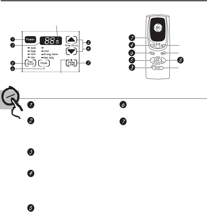
About the controls on the air conditioner.
Features and appearance will vary.
Lights next to the touch pads on the air conditioner control panel indicate the selected settings.
NOTE: The display always |
Light indicates the unit |
shows the room temperature |
is in the temperature or |
except when setting the Set |
delay time Set mode. |
temperature or the Delay timer. |
|
|
|
Heat |
Light indicates the delay timer is set.
Delay 1–24hr
Delay timer
Decrease
Mode select
Fan speed |
Fan |
Fan |
|
Decrease |
|||
|
|
Temperature
set Increase
and Decrease
 Delay timer Increase
 Auto Fan on
Fan speed Increase
 Unit power on/off
Air Conditioner Controls |
Remote Control |
|
Controls
Power Pad
Turns air conditioner on and off. When turned on, the display will show the room temperature.
Display
Shows the room temperature or time remaining on the Delay timer. Shows the Set temperature while setting the temperature in Heat, Cool or Energy Saver modes. The Set light will turn on while setting.
Temp Increase Ÿ/Decrease źPads
Use to set temperature when in Heat, Cool or Energy Saver mode. The Set light will turn on while setting.
Delay Timer IncreaseŸ(+) /Decrease ź(–)
Pads
Each touch of the Increase Ÿ/ Decrease ź pads on the unit or the Increase + / Decrease
– pads on the remote control will set the delay time when using the Delay 1–24hr timer. The Set light will turn on while setting.
Fan Speed Pads
Use to set the fan speed to Low, Med, High or Auto on the unit. NOTE: On the remote control, use the fan speed Increase + / Decrease – pads to set the fan speeds to Low, Med or High. Use the Auto pad to turn Auto fan on.
Mode Pad
Use to set the air conditioner to Heat, Cool, Energy Saver or Fan Only mode.
Delay Pads
'HOD\ 21³When the air conditioner is off, it can be set to automatically come on in 1 to 24 hours at its previous mode and fan settings.
'HOD\ 2))³When the air conditioner is on, it can be set to automatically turn off in 1 to 24 hours.
How to set:
Press the Delay 1–24hr pad on the unit or on the remote control. Each touch of the Increase Ÿ
/ Decreaseźpads on the unit or the Increase + / Decrease – pads on the remote control will set the timer in 1-hour intervals. The Set light will turn on while setting.
To review the remaining time on the Delay 1–24hr timer, press the Delay 1–24hr pad on the unit or on the remote control. Use the Increase Ÿ/ Decrease źpads on the unit or the
Increase + / Decrease – pads on the remote control to set a new time if desired.
To cancel the timer, press the Delay 1–24hr pad until the light on the Delay 1–24hr pad goes off.
Note: The default temperature reading on the display is degree Fahrenheit ( °F). To change the display to degree Celcius (°C), press the Temp Increase Ÿand Temp Decrease źbuttons together and hold for 3 seconds. Repeat the process to change back to degree Fahrenheit (°F)
4

GEAppliances.com
Heat Mode
Use the Heat mode at Low, Med, High or Auto Fan Speed for heating. Use the Temperature Increase Ÿ
/ Decrease źpads to set the desired temperature between 61°F and 86°F in 1°F increments.
An electronic thermostat is used to maintain the room temperature. The heater will cycle on and off to keep the room at the set level of comfort.
Cool Mode
Use the Cool mode at Low, Med, High or Auto Fan Speed for cooling. Use the Temperature Increase Ÿ
/ Decrease źpads to set the desired temperature between 61°F and 86°F in 1°F increments.
An electronic thermostat is used to maintain the room temperature. The compressor will cycle on
and off to keep the room at the set level of comfort. Set the thermostat at a lower number and the indoor air will become cooler. Set the thermostat at a higher number and the indoor air will become warmer.
NOTE: If the air conditioner is off and is then turned on while set to a Cool setting or if turned from a fan
setting to a Cool setting, it may take approximately 3 minutes for the compressor to start and cooling to begin.
Cooling Descriptions
For Normal Cooling³6HOHFW WKH Cool mode and
High or Med fan with a middle set temperature.
For Maximum Cooling³6HOHFW WKH Cool mode and High fan with a lower set temperature.
For Quieter and Nighttime Cooling³6HOHFW WKH
Cool mode and Low fan with a middle set temperature.
Energy Saver Mode
Controls the fan. |
|
ON³7KH IDQ ZLOO F\FOH RQ DQG RII ZLWK WKH |
OFF³7KH IDQ UXQV DOO WKH WLPH ZKLOH WKH FRPSUHVVRU |
compressor. This results in wider variations of room |
cycles on and off. |
temperature and humidity. Normally used when the |
|
room is unoccupied. NOTE: The fan may continue to |
|
run for a short time after the compressor cycles off. |
|
Fan Only Mode
Use the Fan Only Mode at Low, Med or High fan |
NOTE: Auto Fan Speed cannot be used when in the |
speed to provide air circulation and filtering without |
Fan Only Mode. |
cooling. Since fan-only settings do not provide |
|
cooling, a Set temperature cannot be entered. The |
|
room temperature will appear |
|
in the display. |
|
Auto Fan Speed
Set to Auto fan speed for the fan speed to automatically set to the speed needed to provide optimum comfort settings with the set temperature.
If the room needs more cooling, the fan speed
will automatically increase. If the room needs less cooling, the fan speed will automatically decrease.
NOTE: Auto Fan Speed cannot be used when in the
Fan Only Mode.
Remote Control
To ensure proper operation, aim the remote control at the signal receiver on the air conditioner.
Make sure nothing is between the air conditioner and the remote control that could block the signal.
The remote control signal has a range of up to 20 feet.
Make sure batteries are fresh and installed correctly as indicated on the remote control.
Remote contains a magnet allowing it to attach to metal surfaces.
Power Outage Recovery Feature
In the case of a power outage or interruption, the unit will automatically re-start in the settings last used after the power is restored. If the Delay 1–24hr
feature was set, it will resume countdown. You may need to set a new time if desired.
5
About the controls on the air conditioner
Additional important information.
Air Direction
Use the lever to adjust the air direction left and right only.
Care and cleaning of the air conditioner.
Grille and Case
Turn the air conditioner off and remove the plug from the wall outlet before cleaning.
To clean, use water and a mild detergent. Do not use bleach or abrasives.
Air Filter
The air filter behind the front grille should be checked and cleaned at least every 30 days or
more often if necessary.
To remove:
Open the inlet grille by pulling downward on the tabs at the top upper corners of the inlet grille until the grille is in a 45º position. Remove the filter.
Clean the filter with warm, soapy water. Rinse and let the filter dry before replacing it. Do not clean the filter in a dishwasher.
 CAUTION:DO NOT operate the air conditioner without a filter because dirt and lint will clog it and reduce performance.
Tab
Outdoor Coils
The coils on the outdoor side of the air conditioner should be checked regularly. If they are clogged with dirt or soot, they may be professionally cleaned.
How to Insert the Batteries in the Remote Control
1
2
3
Remove the battery cover by sliding it according to the arrow direction.
Insert new batteries, making sure that the (+) and (–) of battery are installed correctly.
Reattach the cover by sliding it back into position.
NOTES:
Use 2 “AAA” (1.5 volt) alkaline batteries. Do not use rechargeable batteries.
Remove the batteries from the remote control if the system is not going to be used for a long time.
Do not mix old and new batteries. Do not mix alkaline, standard (carbon-zinc) or rechargeable (ni-cad, ni-mh, etc) batteries.
6
Installation |
Air Conditioner |
Instructions |
|
Questions? Call 800.GE.CARES (800.432.2737) or Visit our Website at: GEAppliances.com
In Canada, call 1.800.561.3344 or visit www.GEAppliances.ca
 BEFORE YOU BEGIN
Read these instructions completely and carefully.
t IMPORTANT — Save these instructions for local inspector’s use.
t IMPORTANT — Observe all governing codes and ordinances.
t Note to Installer – Be sure to leave these instructions with the Consumer.
t Note to Consumer – Keep these instructions for future reference.
t Skill level – Installation of this appliance requires basic mechanical skills.
t Completion time – Approximately 1 hour
t We recommend that two people install this product.
t Proper installation is the responsibility of the installer.
t Product failure due to improper installation is not covered under the Warranty.
t You MUST use all supplied parts and use proper installation procedures as described in these instructions when installing this air conditioner.
 ELECTRICAL REQUIREMENTS
Some models require a 115/120-volt AC, 60-Hz grounded outlet protected with a 15-amp time-delay fuse or circuit breaker.
The 3-prong grounding plug minimizes the possibility of electric shock hazard. If the wall outlet you plan to use is only a 2-prong outlet, it is your responsibility to have it replaced with a properly grounded 3-prong wall outlet.
Some models require 230/208-volt AC, protected with a time-delay fuse or circuit breaker. These models should be installed on their own single branch circuit for best performance and to prevent overloading house or apartment wiring circuits, which could cause a possible fire hazard from overheating wires.
 CAUTION:
Do not, under any circumstances, cut or remove the third (ground) prong from the power cord.
Do not change the plug on the power cord of this air conditioner.
Aluminum house wiring may present special problems—consult a qualified electrician.
TOOLS YOU WILL NEED |
|
|
Phillips head screwdriver |
|
Flat-blade screwdriver |
Pencil |
Ruler or tape measure |
Level |
Scissors or knife |
Power cord includes a current interrupter device. A test and reset button is provided on the plug case. The device should be tested on a periodic basis by first pressing the TEST button and then the RESET button while plugged into the outlet. If the TEST button does not trip or if the RESET button will not stay engaged, discontinue use of the air conditioner and contact a qualified service technician.
7
Installation Instructions
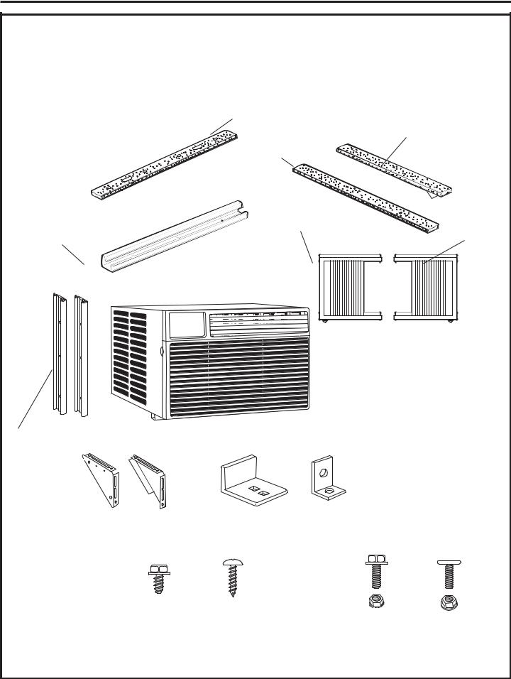
PARTS INCLUDED |
|
|
|
(Appearance may vary) |
|
|
|
|
Top rail gasket (1) |
|
|
|
|
Window |
|
|
Foam top window |
sash seal |
|
|
|
|
|
|
gasket (1) |
|
|
|
Left |
|
|
Top |
accordion |
|
Right |
panel |
|
accordion |
|
mounting |
|
||
|
|
panel |
|
rail |
|
|
|
|
|
|
|
Side rail (2) |
|
|
|
V-supports (2) |
Sill angle |
Window |
|
bracket (2) |
locking bracket |
|
|
|
|
||
|
|
(1) |
|
Type A |
Type C |
Type E bolt |
Type F bolt |
screws (10) |
screws (5) |
||
|
|
with nut (4) |
with nut (2) |
|
8 |
|
|
Installation Instructions
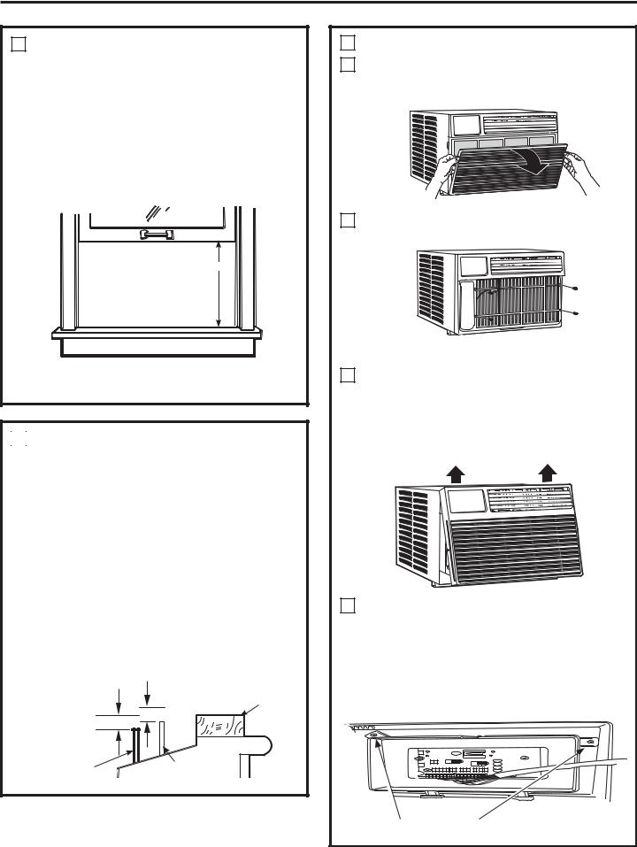
1 WINDOW REQUIREMENTS
tThese instructions are for a standard double-hung window. You will need to modify them for other types of windows.
tAll supporting parts must be secured to firm wood, masonry or metal.
tThe electrical outlet must be within reach of the power cord.
tFollow the dimensions in the table and illustration for your model.
19 1/4”
 29” - 41”
(With accordion panels)
2 STORM WINDOW REQUIREMENTS
A storm window frame will not allow the air conditioner to tilt toward the outside, and will keep it from draining properly.
To adjust for this, attach a piece of wood to the sill.
WOOD PIECES WIDTH: 2”
LENGTH: Long enough to fit inside the window frame.
THICKNESS: The top of the wood should be 1/2” higher than the top of the storm window frame or the vinyl frame.
Attach securely with nails or screws provided by the installer.
|
1/2shigher |
|
|
than vinyl frame |
|
|
(on some windows) |
|
1/2shigher |
Wood |
|
|
||
than storm |
|
|
window |
Sill |
|
frame |
||
|
||
Storm window |
Vinyl frame |
|
frame |
||
|
3
A
B
C
D
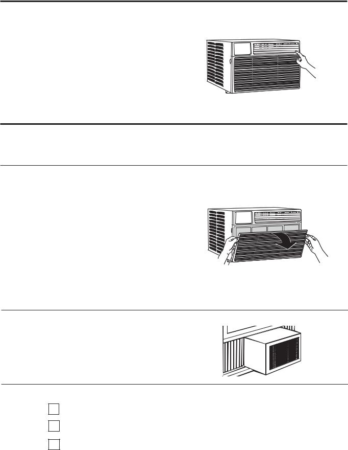
PREPARE THE AIR CONDITIONER
Pull the top of the front panel out and down. Remove the filter. Remove the front panel by lifting up at an angle.
Remove the four front screws. Save them for reinstalling the front housing.
Grasp the lower corners of the grille while pressing in on the case sides with your finger tips. Pull out to release and lift it up.
NOTE: Do not pull the bottom edge toward you more than 3s or you may damage the tabs of the grille.
When the front grille is removed the control panel will still be attached by a harness. Turn the grille around so you can see the back side of the grille.
Remove the 2 screws to separate the
control panel housing from the grille.
NOTE: Be sure to save these screws. You will need them later in the installation.
9

Installation Instructions
3PREPARE THE AIR CONDITIONER (continues)
ERemove the shipping screws located on the top of the case.
FRemove the ground screws from each side of the case. Keep them in a safe location. NOTE: Be sure to save the ground screws. You will need them later in the installation.
GSlide the air conditioner from the case by gripping the base pan handle, lifting up on the air conditioner, and pulling forward. Have a second person brace the case. Do not pull or lift on the styrofoam discharge area.
Do not pull
or lift
in this
area—
damage
to the
unit may
result
FRONT
HYour unit may come with internal packaging. This packaging must be removed prior to installing the air conditioner back into the cabinet.
4 PREPARE THE CASE
AAttach the top rail gasket to the bottom of the top mounting rail.
BInstall the top mounting rail with 4 type A screws from the inside of the case. Press firmly to drive the screws into the gasket and through the top mounting rail.
Top mounting rail
CSlide each side rail onto the edge of each according panel. The figure shows the orientation of each accordion panel and side retainer assembly relative to the case from a top view of the unit.
Side Rail
Window Filler Panel
Side Rail
Window Filler Panel
DSlide the left and right accordion panels into the top and bottom mounting rails.
Top right Top left 
Bottom mounting rail
10
Installation Instructions
4 PREPARE THE CASE (continues)
EAttach the side retainers to the case using 6 type A screws. Mount the screws from the inside of the wall case.
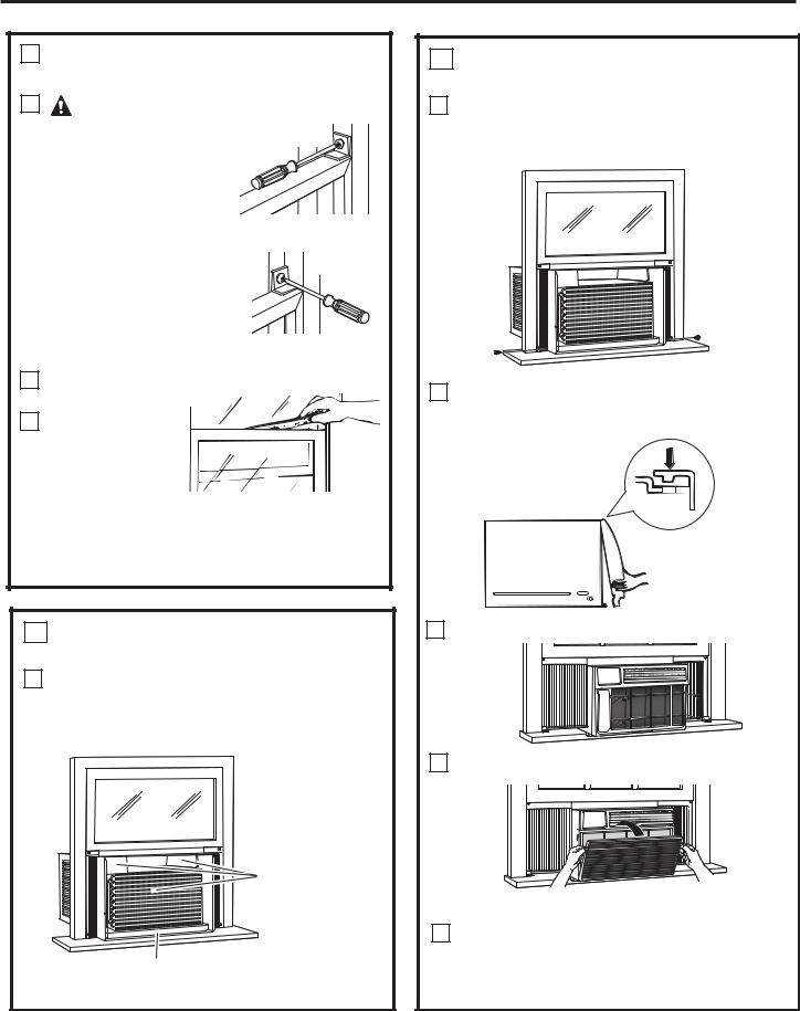
5PREPARE THE WINDOW AND INSTALL THE CASE
ACut the window sash seal to the length of the window sash. Peel off the backing and attach the seal to the underside of the window sash.
BOpen the window and mark the center of the window sill.
CCarefully slide the case into the window and center the case. Lower the window behind the top mounting rail. Pull the bottom of the case forward so that the bottom mounting rail is tight against the back of the window sill. Mount the case to the window sill using 2 type C screws.
Drill pilot holes, if necessary.
2 type C screws
Sill
5 PREPARE THE WINDOW AND INSTALL
THE CASE (continues)
DAssemble the V-support and Sill Angle bracket with Type F nut and bolt
|
Type E bolt |
|
and nut |
|
Left |
Sill angle |
Right |
bracket |
|
V-support Type
F bolt and nut
E Position the left V-support under the left side panel of the wall case and against the outside wall. Adjust the
Sill Angle Bracket to rest on the sill. Attach
the V-support to the wall case using 2 Type E bolts. Re-adjust the Sill Angle Bracket if necessary.
F Repeat with Right V-Support.
 Sill
Sill


 V-support
GExtend the left and right accordion panels to the vertical window sashes. Drill pilot holes and attach the top corners with 2 type C screws.
Type C |
Type C |
|
screw |
||
screw |
||
|
11
Installation Instructions
5 PREPARE THE WINDOW AND INSTALL
THE CASE (continues)
H |
CAUTION: |
|
|
|
|
|
To prevent broken |
Vinyl |
|
glass or damage to |
|
|
windows, on vinyl or |
|
|
other similarly |
|
|
constructed windows, |
|
|
attach the window |
|
|
locking bracket to the window side jamb. |
|
|
Attach the window locking |
Wood |
|
bracket with one Type C |
|
|
|
|
|
screw. |
|
ICut the foam top window gasket to the
window width.
J Stuff the foam between the
glass and the
window to  prevent air and
 insects from getting into the room.
NOTE: If the gasket supplied does not fit your window, obtain appropriate material locally to provide a proper installation seal.
6 INSTALL THE AIR CONDITIONER IN THE CASE
ASlide the air conditioner into the case by the base pan. Do not push on the controls,
styrofoam air discharge housing or the finned coils. Make sure the air conditioner is firmly seated.
Do not press on
WKHVH DUHDV³ damage to the unit may result
Base Pan
6
B
C
D
E
F
INSTALL THE AIR CONDITIONER IN THE CASE (continues)
Replace the 2 screws removed earlier, one
on each side of the case.
IMPORTANT: THE GROUND SCREWS MUST BE REINSTALLED TO ENSURE PROPER GOUND.
Attach the front grille to the case by inserting the tabs on the grille into the slots on the front top of the case. Push the grille in.
Replace the screws.
Install the filter and the front grille.
Plug in the air conditioner.
12
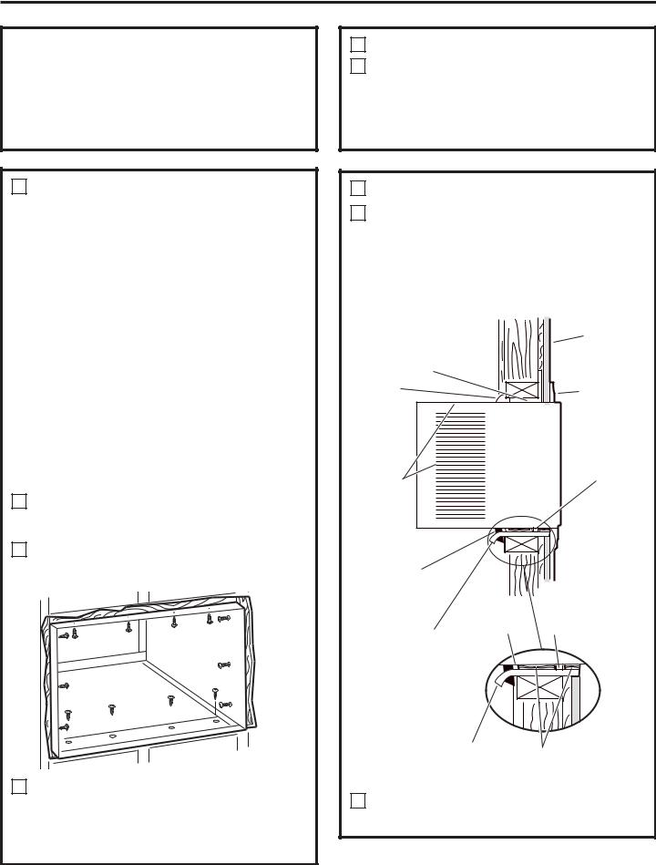
Through-the-Wall Installation Instructions—Optional
The case may be installed through-the-wall in both existing and new construction.
Read completely, then follow step-by-step.
NOTE: Obtain all materials locally for mounting the air conditioner through- the-wall.
1 IMPORTANT
Through-the-wall installation is not appropriate if any of the side or top louvers in the case will be obstructed by the wall.
All side and top louvers in the case must project on the outdoor side of the wall.
The room side of the case must project into the room far enough to maximize the balance of the unit.
The case must be installed level from side- to-side and with a slight tilt from front to rear. Use a level; no more than a 1/2 bubble will be the correct case slant to the outside.
Lintel angle is required to support bricks or blocks above opening.
Flashing is required and should extend the length of the opening to ensure no inside cavity leakage occurs.
ARemove the air conditioner from the case.
For specific instruction, refer to the Window
Installation Instructions.
BMake certain that a wall receptacle is available close to the hole location or make arrangements to install a receptacle.
CPlace the case in the wall opening and place wood support strips between the case bottom and the flashing on both sides of the bottom rail. They should be the same height as the bottom rail and the same length as the wall opening.
1 IMPORTANT (cont.)
DSecure with 14 wood screws anchored at least an inch into the wall support structure.
NOTE: Drill pilot holes, if necessary, for proper installation. If the frame is oversized, use shims to prevent case distortion.
2 FINISH THE WALL OPENING
ACaulk all four sides on the outdoor side of the case to prevent moisture from getting through to the interior wall. Use of flashing
(drip rail) will further prevent water from dripping inside the wall and down the outside of the building.
|
Plaster line |
|
Lintel angle |
|
|
Caulking |
Trim molding (if |
|
|
desired) |
|
OUTSIDE |
INSIDE |
|
|
||
Air louvers (top |
|
|
and sides must |
Bottom rail |
|
project on the |
||
|
||
outdoor side of |
|
|
the wall) |
|
Wood filler and caulking (above and below the flashing)
Case Bottom Flashing bottom rail (Drip rail)
Flashing |
|
(Drip rail) |
Wood support strips |
|
BPlace the air conditioner into the case.
For specific instruction, refer to the Window
Installation Instructions.
13

Troubleshooting Tips.
Problem |
Possible Causes |
What To Do |
|
|
|
Air conditioner |
The air conditioner |
tMake sure the air conditioner plug is pushed |
does not start |
is unplugged. |
completely into the outlet. |
|
|
|
|
The fuse is blown/circuit |
tCheck the house fuse/circuit breaker box and replace |
|
breaker is tripped. |
the fuse or reset the breaker. |
|
|
|
|
Power failure. |
tThe unit will automatically restart in the settings last |
|
|
used after the power is restored. |
|
|
tThere is a protective time delay (approximately |
|
|
3 minutes) to prevent tripping of the compressor |
|
|
overload. For this reason, the unit may not start |
|
|
normal cooling for 3 minutes after it is turned |
|
|
back on. |
|
|
|
|
The current interrupter |
tPress the RESET button located on the power cord plug. |
|
device is tripped. |
tIf the RESET button will not stay engaged, discontinue |
|
|
use of the air conditioner and contact a qualified |
|
|
service technician. |
|
|
|
Air conditioner does |
Airflow is restricted. |
tMake sure there are no curtains, blinds or furniture |
not cool as it should |
|
blocking the front of the air conditioner. |
|
|
|
|
The temp control may |
tIn the Cool mode, press the Decrease dpad. |
|
not be set correctly. |
|
The air filter is dirty.
tClean the filter at least every 30 days. See the Care and Cleaning section.
The room may have been hot.
tWhen the air conditioner is first turned on, you need to allow time for the room to cool down.
|
Cold air is escaping. |
tCheck for open furnace registers and cold air returns. |
|
|
|
|
Cooling coils have iced up. |
tSee “Air conditioner freezing up” below. |
|
|
|
Air conditioner |
,FH EORFNV WKH DLU IORZ |
6HW WKH FRQWUROV DW High Fan or High Cool and set the |
freezing up |
and stops the air conditioner |
thermostat to a higher temperature. |
|
from cooling the room. |
|
|
|
|
The remote control |
The batteries are inserted |
tCheck the position of the batteries. They should be |
is not working |
incorrectly. |
inserted in the opposite (+) and (–) direction. |
|
|
|
|
The batteries may be dead. |
tReplace the batteries. |
|
|
|
Water drips outside |
Hot, humid weather. |
tThis is normal. |
|
|
|
Water drips indoors |
The air conditioner is not |
tFor proper water disposal, make sure the air conditioner |
|
tilted to the outside. |
slants slightly from the case front to the rear. |
|
|
|
Water collects in |
Moisture removed from air |
tThis is normal for a short period in areas with little |
base pan |
and drains into base pan. |
humidity; normal for a longer period in very humid areas. |
Normal Operating Sounds
You may hear a pinging noise caused by water being picked up and thrown against the condenser on rainy days or when the humidity is high. This design feature helps remove moisture and improve efficiency.
You may hear the thermostat click when the compressor cycles on and off.
14
Water will collect in the base pan during high humidity or on rainy days. The water may overflow and drip from the outdoor side of the unit.
The fan may run even when the compressor does not.

Notes.
15

Notes.
16
GE Air Conditioner—One Year Limited Warranty. (For customers in the U.S.A.)
All warranty service provided by our Factory Service Centers,
or an authorized Customer Care® technician. To schedule service, visit us on-line at GEAppliances.com, or call 800.GE.CARES (800.432.2737). Have serial number and model number available when calling for service.
Staple your receipt here. Proof of the original purchase date is needed to obtain service under
the warranty.
For The Period Of: |
GE Will Replace: |
One Year |
Any part of the air conditioner which fails due to a defect in materials or workmanship. |
From the date of the |
During this limited one-year warranty, GE will also provide, free of charge, all labor and related |
original purchase |
service to replace the defective part. |
|
|
|
|
What Is Not Covered:
Service trips to your home to teach you how to use the product.
Improper installation, delivery or maintenance. If you have an installation problem, or if the air conditioner is of improper cooling capacity for the intended use, contact your dealer or installer. You are responsible for providing adequate electrical connecting facilities.
Failure of the product resulting from modifications to the product or due to unreasonable use including failure to provide reasonable and necessary maintenance.
In commercial locations, labor necessary to move the unit to a location where it is accessible for service by an individual technician.
Replacement of house fuses or resetting of circuit breakers.
Failure due to corrosion on models not corrosionprotected.
Damage to the product caused by improper power supply voltage, accident, fire, floods or acts of God.
Incidental or consequential damage caused by possible defects with this air conditioner.
Damage caused after delivery.
EXCLUSION OF IMPLIED WARRANTIES—Your sole and exclusive remedy is product repair as provided in this Limited Warranty. Any implied warranties, including the implied warranties of merchantability or fitness for a particular purpose, are limited to one year or the shortest period allowed by law.
This warranty is extended to the original purchaser and any succeeding owner for products purchased for home use within the USA. If the product is located in an area where service by a GE Authorized Servicer is not available, you may be responsible for a trip charge or you may be required to bring the product to an
Authorized GE Service location for service. In Alaska, the warranty excludes the cost of shipping or service calls to your home.
Some states do not allow the exclusion or limitation of incidental or consequential damages. This warranty gives you specific legal rights, and you may also have other rights which vary from state to state. To know what your legal rights are, consult your local or state consumer affairs office or your state’s Attorney General.
Warrantor: General Electric Company. Louisville, KY 40225
17
 Loading...