


AEE24DTH2
GEAppliances.com
Safety Instructions ............. 2, 3
Operating Instructions
Controls ........................... 4-6
Care and Cleaning
Air Filter .............................. 6
Outdoor Coils ......................... 6
Installation Instructions ...... 7-1s
AEE24
0_
Troubleshooting Tips ............ 14
Normal Operating Sounds ............ 14
Consumer Support
Consumer Support .......... Back Cover
Ownership Registration for
Customers in Canada only ........ 15, 16
Warranty for Customers
in Canada ........................... 18
Warranty for Customers
in the U.S.A........................... 17
Climatiseur
La section franqaise commence (_ la page 19
Acondicionador
deaire
La secci6n en espaflol empieza en la p6gina 37
®
Write the model and serial numbers here:
Model #
Serial #
Find these numbers on a label on the side of
the air conditioner.
In Canada, contact us at:
www.GEAppliances.ca
49-7667-210-12GE

iMPORTANTSAFETYINFORMATION.
READALLiNSTRUCTiONSBEFOREUSING.
A
Foryour safety, the information inthis manual must be followed to minimize the risk of fire, electric shock
or personal injury.
m
SAFETYPRECAUTIONS
Use this appliance only for its intended
purpose as described in this Owner's
Manual.
iiM
This air conditioner must be properly
installed in accordance with the Installation
Instructions before it is used.
iiM
Never unplug your air conditioner by pulling
on the power cord. Always grip plug firmly
and pull straight out from the receptacle.
iiM
Replace immediately all electric service
cords that have become frayed or otherwise
damaged. A damaged power supply cord
must be replaced with a new power supply
cord obtained from the manufacturer and
not repaired. Do not use a cord that shows
cracks or abrasion damage along its length
or at either the plug or connector end.
iiiiiiiiiiii_iiiii
Turn the unit OFFand unplug your air
conditioner before cleaning.
iiM
GEdoes not support any servicing of the
air conditioner. We strongly recommend
that you do not attempt to service the air
conditioner yourself.
For your safety...do not store or use
combustible materials, gasoline or other
flammable vapors or liquids in the vicinity
of this or any other appliance.
iiM
All air conditioners contain refrigerants,
which under federal law must be removed
prior to product disposal. If you are getting
rid of an old product with refrigerants, check
with the company handling disposal about
what to do.
If the receptacle does not match the plug,
the receptacle must be changed out by a
qualified electrician.
These R410A air conditioning systems
require contractors and technicians to
use tools, equipment and safety standards
approved for use with this refrigerant.
DO NOT use equipment certified for
R22 refrigerant only.
HOWTOCONNECTELECTRICITY
Do not, under any circumstances, cut or remove
the third (ground) prong from the power cord.
For personal safety, this appliance must be properly
grounded.
DONOTuse an adapterp/ug with thisappliance.
The power cord of this appliance is equipped
with a 3-prong (grounding) plug which mates
with a standard 3-prong (grounding) wall outlet
to minimize the possibility of electric shock
hazard from this appliance.
Power cord includes a current interrupter device.
A test and reset button is provided on the plug
case. The device should be tested on a periodic
basis by first pressing the TESTbutton and
then the RESETbutton while plugged into the
outlet. If the TESTbutton does not trip or if the
RESETbutton will not stay engaged, discontinue
use of the air conditioner and contact a qualified
2
service technician.
Have the wall outlet and circuit checked by
a qualified electrician to make sure the outlet
is properly grounded.
Where a 2-prong wall outlet is encountered,
it isyour personal responsibility and obligation to
have it replaced with a properly grounded
3-prong wall outlet.
The air conditioner should always be plugged
into its own individual electrical outlet which has
a voltage rating that matches the rating plate.
This provides the best performance and also
prevents overloading house wiring circuits which
could cause a fire hazard from overheated wires.
See the Installation Instructions, Electrical
Requirementssection for specific electrical
connection requirements.
GEAppliances.c0m
A
USEOFEXTENSIONCORDS
RISK OF FIRE. Could cause serious injury or
death.
,, DO NOT use an extension cord with this
Window Air Conditioner.
,, DO NOT use surge protectors or multi-outlet
adaptors with this Window Air Conditioner.
READANDFOLLOWTHiSSAFETY/NFORMATIONCAREFULLY
SAVETHESEiNSTRUCTiONS
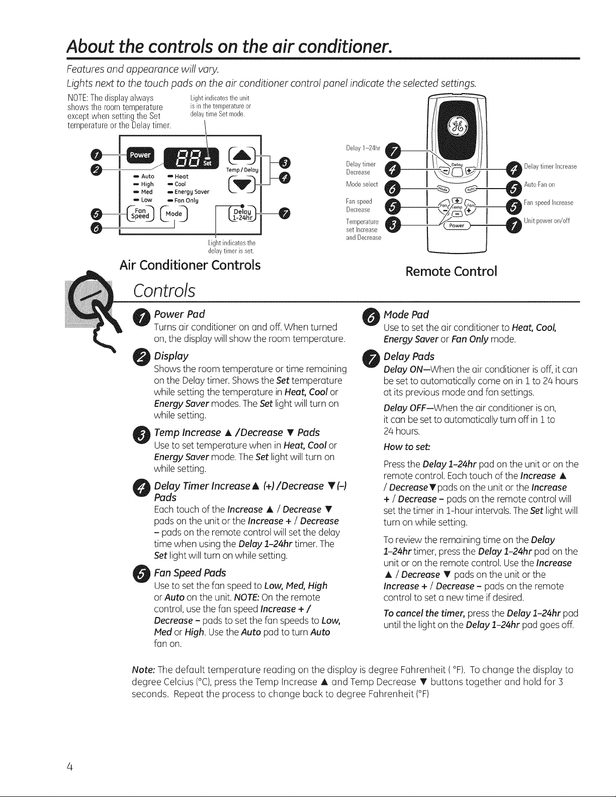
About the controls on the air conditioner.
Features and appearance will vary.
Lights next to the touch pads on the air conditioner control panel indicate the selected settings.
NOTE:Thedisplayalways
shows the room temperature
except when setting the Set
temperatureortheDelaytimer.
Lightindicates the unit
is inthe temperatureor
delaytime Set mode.
o Auto amHeat
,,, High ,,- Cool
m Med m Energg Saver
_, LOW am,Fan Onlg
--_peed ._ d O
O L
Air Conditioner Controls
Controls
Power Pad
Turnsair conditioner on and off. When turned
on,the display will show the room temperature.
Display
Showsthe room temperature or time remaining
on the Delaytimer. Shows the Settemperature
while setting the temperature inHeat, Cool or
Energy Saver modes.The Set light will turn on
while setting.
Temp Increase A/Decrease T Pads
Use to set temperature when in Heat, Cool or
Energy Saver mode. The Set light willturn on
while setting.
Delay Timer Increase A (+)/Decrease T (-)
Pads
Eachtouch of the Increase A / Decrease T
pads on the unit or the Increase + / Decrease
- padson the remote control will setthe delay
time when usingthe Delay 1-24hr timer. The
Setlight will turn on while setting.
FanSpeedPads
Useto set the fan speed to Low, Meal,High
or Auto on the unit. NOTE:Onthe remote
control, usethe fan speedIncrease + /
Decrease - pads to set the fan speeds to Low,
Mealor High. Usethe Auto pad to turn Auto
fan on.
Delaytimer hcrease
Auto Fan on
FanspeedIncrease
F-T- o
Unit poweron/off
Lightindicatesthe
delay timer is set.
Mode Pad
Useto set the air conditioner to Heat, Cool,
Energy Saver or Fan Only mode.
Delay Pads
Delay ON--When the air conditioner isoff, it can
be set to automatically come on in 1to 24 hours
at its previous mode and fan settings.
Delay OFF--When the air conditioner ison,
it can be set to automatically turn off in I to
24 hours.
How to set:
Press the Delay 1-24hr pad on the unit or on the
remote control. Each touch ofthe Increase A
I OecreaseTpads on the unit or the Increase
+ / Decrease - pads on the remote control will
set the timer in 1-hour intervals. The Set light will
turn on while setting.
Toreview the remaining time on the Delay
1-24hr timer, pressthe Delay 1-24hr pad on the
unit or on the remote control. Usethe Increase
A / Decrease T pads on the unit or the
Increase + / Decrease- pads on the remote
control to set a new time if desired.
Tocancel the timer, pressthe Delay 1-24hr pad
until the light on the Delay 1-24hr pad goes off.
Note: The default temperature reading on the display is degree Fahrenheit (°F). To change the display to
degree Celcius (°C),pressthe Temp Increase A and Temp Decrease T buttons together and hold for 3
seconds. Repeatthe process to change back to degree Fahrenheit (°F)
4
Heat Mode
Usethe Heat mode at Low, Med,High or Auto Fan
Speedfor heating. Usethe Temperature Increase A
/ Decrease T pads to set the desiredtemperature
between 61°Fand 86°Fin I°F increments.
Cool Mode
Usethe Cool mode at Low, Meal,High or Auto Fan
Speedfor cooling. Usethe Temperature Increase A
/ Decrease T padsto set the desired temperature
between 61°Fand 86% in L°Fincrements.
An electronicthermostat isusedto maintain the room
temperature. Thecompressorwill cycleon
and off to keepthe room atthe setlevelof comfort.
Setthe thermostat at a lower number and the indoor
air will become cooler.Setthe thermostat at a higher
number and the indoor air will become warmer.
NOTE:Ifthe air conditioner is off and isthen turned on
while set to a Coolsetting or ifturned from a fan
Energy Saver Mode
Controlsthe fan.
ON--The fun will cycle on and off with the
compressor.This results in wider variations of room
temperature and humidity. Normally usedwhen the
room isunoccupied. NOTE:Thefan may continue to
run for a short time after the compressor cyclesoff.
GEAppliances.com
An electronicthermostat isusedto maintain the room
temperature, Theheaterwill cycle on and off to keep
the room at the set levelof comfort.
setting to a Cool setting, it may take approximately
3 minutes for the compressor to start and cooling to
begin.
Cooling Descriptions
For Normal Cooling--Select the Cool mode and
High or Medfan with a middle set temperature.
For Maximum Cooling--Select the Cool mode
and High fan with a lower settemperature.
For Quieter and Nighttime Cooling-Select the
Cool mode and Low fan with a middle set
temperature.
OFF--Thefan runs all the time, while the compressor
cycleson and off.
Fan Only Mode
Usethe FanOnly Mode at Low, Medor Highfan
speed to provide air circulation and filtering without
cooling. Sincefan-only settings do not provide
cooling, a Settemperature cannot be entered. The
room temperature will appear
in the display.
Auto Fan Speed
Setto Auto fan speedfor the fan speed to
automatically set to the speed neededto provide
optimum comfort settings with the set temperature.
Ifthe room needs more cooling,the fan speed
Remote Control
Toensure proper operation, aim the remote
control at the signal receiver on the air
conditioner.
Hake sure nothing isbetween the air conditioner
and the remote control that could block the
signal.
Power Outage Recovery Feature
Inthe case of a power outage or interruption, the
unit will automatically re-start in the settings last
used after the power isrestored. Ifthe Delay!-24hr
NOTE:Auto FanSpeedcannot be usedwhen in the
Fan Only Mode.
will automatically increase. If the room needs less
cooling, the fan speed will automatically decrease.
NOTE:Auto FanSpeedcannot be usedwhen in the
Fan Only Mode.
Theremote control signal has a range of
up to 20 feet.
Make sure batteries are fresh and installed
correctly as indicated on the remote control.
Remotecontains a magnet allowing it to attach
to metal surfaces.
feature was set,it will resume countdown. You may
need to set a new time if desired.
About the controls on the air conditioner
Additional important information.
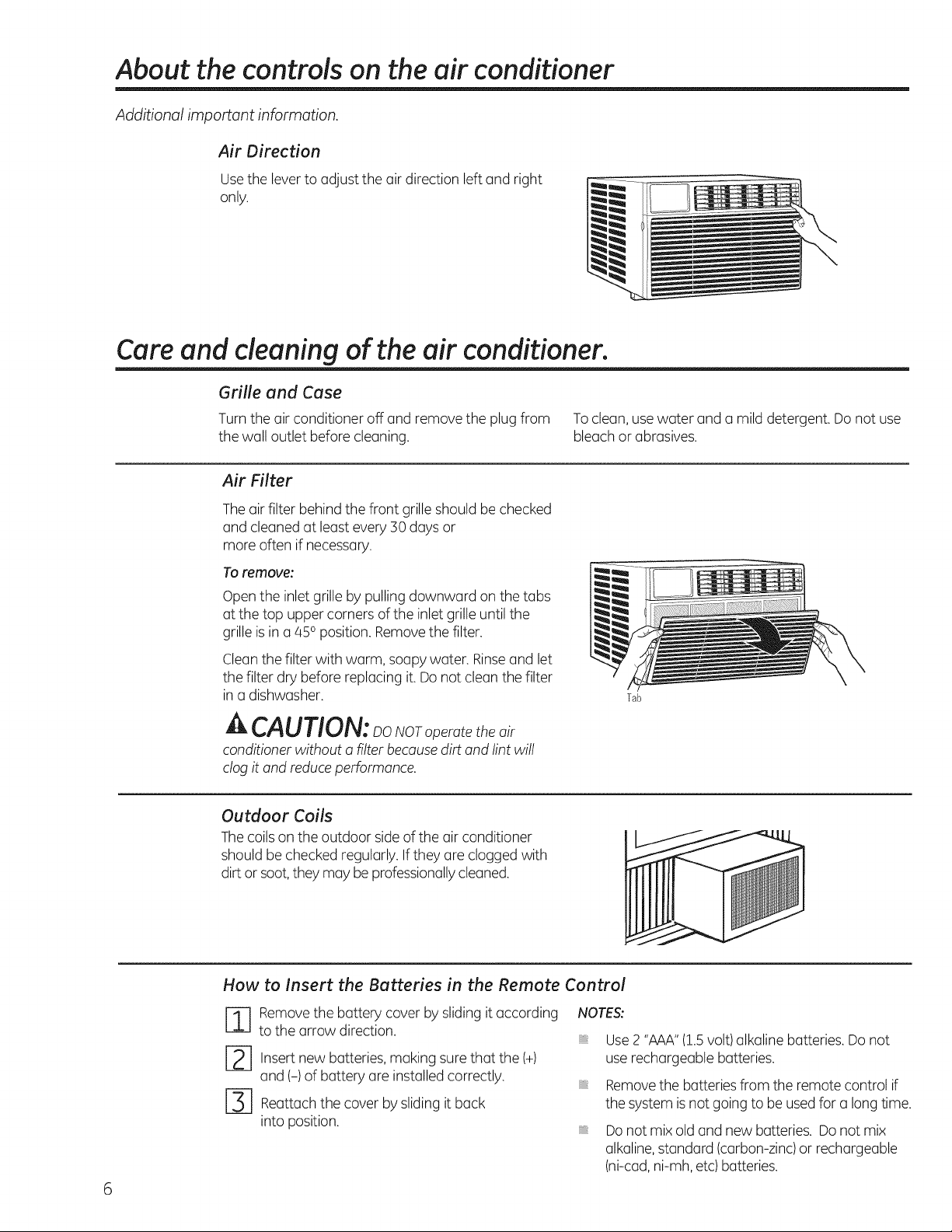
Air Direction
Usethe leverto adjust the air direction left and right
only.
Care and cleaning of the air conditioner.
Grille and Case
Turn the air conditioner off and remove the plug from
the wall outlet before cleaning.
Air Filter
Theair filter behind the front grille should be checked
and cleaned at least every 30 days or
more often if necessary.
To remove:
Open the inlet grille by pulling downward on the tabs
at the top upper corners of the inlet grille until the
grille is in a 450position. Removethe filter.
Cleanthe filter with warm, soapy water. Rinseand let
the filter dry before replacing it. Donot cleanthe filter
in a dishwasher.
A CAUTION: DoNOroperatetheair
conditioner without a filter because dirt and lint will
clog it and reduce performance.
Outdoor Coils
Thecoils on the outdoor sideof the air conditioner
should be checked regularly. Ifthey are clogged with
dirt or soot,they may be professionallycleaned.
Toclean, usewater and a mild detergent. Do not use
bleachor abrasives.
Tab
How to insert the Batteries in the Remote Control
-] emove the battery cover by sliding it according
to the arrow direction.
[2-2-] Insert new batteries, making sure that the (+)
and (-) of battery are installed correctly.
[-3] Reuttuchthe cover by slidingit back
into position.
6
NOTES:
Use2 "AAA"(1.5volt) alkaline batteries. Do not
use rechargeable batteries.
Removethe batteries from the remote control if
the system isnot going to be used for a long time.
Donot mix old and new batteries. Do not mix
alkaline,standard (carbon-zinc)or rechargeable
(ni-cad,ni-mh, etc) batteries.

II i
Co i
I struct"
|
BEFOREYOU BEGIN
Read these instructions completely
and carefully.
• IMPORTANT- Savetheseinstructions
for local inspector's use.
• IMPORTANT- Observeallgoverning
codes and ordinances.
,, Note to Installer - Be sure to leave these
instructions with the Consumer.
* Note to Consumer - Keep these instructions for
future reference.
* Skill level - Installation of this appliance
requires basic mechanical skills.
,, Completion time - Approximately 1 hour
,, We recommend that two people install
this product.
,, Proper installation is the responsibility
of the installer.
* Product failure due to improper installation is not
covered under the Warranty.
,, You HUST use all supplied parts and use proper
installation procedures as described in these
instructions when installing this air conditioner.
ACAUTION:
Do not, under any circumstances, cut or remove
the third (ground) prong from the power cord.
Do not change the plug on the power cord
of this air conditioner.
Aluminum house wiring may present special
problems--consult a qualified electrician.
TOOLSYOUWILL NEED
Phillips head screwdriver
Flat-blade screwdriver
ELECTRICALREQUIREMENTS
Some models require a 115/120-volt AC,
60-Hz grounded outlet protected with a
15-amp time-delay fuse or circuit breaker.
The 3-prong grounding plug minimizes the
possibility of electric shock hazard. If the wall outlet
you plan to use is only a 2-prong outlet, it is your
responsibility to have it replaced with a properly
grounded 3-prong wall outlet.
Some models require 230/208-volt AC,
protected with a time-delay fuse or circuit
breaker. These models should be installed on
their own single branch circuit for best
performance and to prevent overloading
house or apartment wiring circuits, which
could cause a possible fire hazard from
overheating wires.
Pencil
Level Scissors or knife
Power cord includes a current interrupter device. A
test and reset button is provided on the plug case. The
device should be tested on a periodic basis by first
pressing the TEST button and then the RESET button
while plugged into the outlet. Ifthe TEST button does
not trip or if the RESET button will not stay engaged,
discontinue use of the air conditioner and contact a
qualified service technician.
Ruler or tape measure
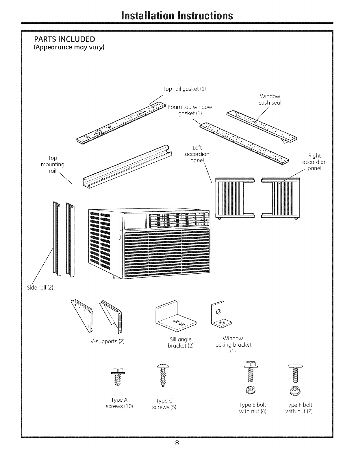
PARTS INCLUDED
(Appearance may vary)
JnstaJlationinstructions
Top rail gasket (!)
saW_ds°i,
Foam top window /
gasket(i) __ /
mounting _ pan
Side rail (2)
ac
Right
accordion
panel
V-supports (2)
Sillangle
bracket (2)
Window
locking bracket
(1)
@ @
Type A Type C
screws (!0) screws (5) Type Ebolt Type Fbolt
8
with nut (4) with nut (2)
installation instructions
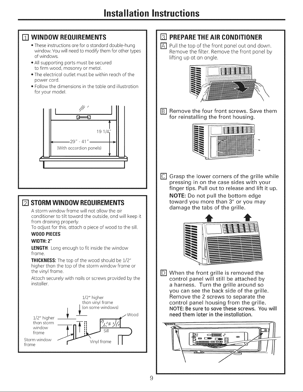
[] WINDOW REQUIREMENTS
• These instructions are for u standard double-hung
window. You will need to modify them for other types
of windows.
• All supporting parts must be secured
to firm wood, masonry or metal.
• The electrical outlet must be within reach of the
power cord.
• Follow the dimensions in the table and illustration
for your model.
I
19 1/4"
_-------29" - 41 "
(With accordion panels)
STORMWINDOW REQUIREMENTS
A storm window frame will not allow the air
conditioner to tilt toward the outside, and will keep it
from draining properly.
To adjust for this, attach u piece of wood to the sill.
WOODPIECES
WIDTH:2"
LENGTH:Long enough to fit inside the window
frame.
THICKNESS:The top of the wood should be 1/2"
higher than the top of the storm window frame or
the vinyl frame.
Attach securely with nails or screws provided by the
installer.
1/2" higher
than vinylframe
_ (on some windows)
1/2" higher
than storm
window
frame
Storm window
frame
- r_ Vinylframe I
_ Wood
D PREPARETHEAiR CONDITIONER
r_ Pull the top of the front panel out and down.
Remove the filter. Remove the front panel by
lifting up at an angle.
r_ Remove the four front screws. Save them
for reinstalling the front housing.
rCl Grasp the lower corners of the grille while
pressing in on the case sides with your
finger tips. Pull out to release and lift it up.
NOTE: Do not pull the bottom edge
toward you more than 3" or you may
damage the tabs of the grille.
t t
@When the front grille is removed the
control panel will still be attached by
a harness. Turn the grille around so
you can see the back side of the grille.
Remove the 2 screws to separate the
control panel housing from the grille.
NOTE: Be sure to save these screws. You will
need them later in the installation.
9
InstaJiationInstructions
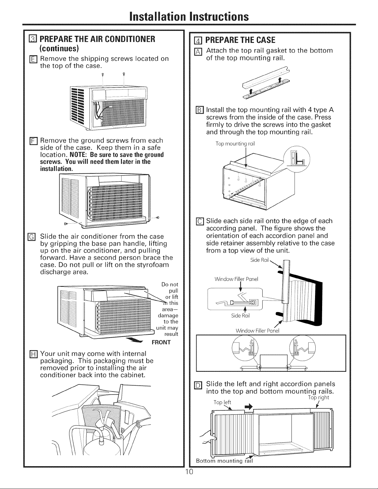
PREPARETHEAiR CONDiTiONER
(continues)
r_ Remove the shipping screws located on
the top of the case.
i
F1 Remove the ground screws from each
side of the case. Keep them inasafe
location. NOTE: Be sure to save the ground
screws. You will need them later in the
installation.
R] PREPARETHECASE
r_ Attach the top rail gasket to the bottom
of the top mounting rail.
r_ Install the top mounting rail with 4 type A
screws from the inside of the case. Press
firmly to drive the screws into the gasket
and through the top mounting rail.
Top mounting rail
Slide the air conditioner from the case
@
by gripping the base pan handle, lifting
up on the air conditioner, and pulling
forward. Have a second person brace the
case. Do not pull or lift on the styrofoam
discharge area.
% FRONT
Eli Your unit may come with internal
packaging. This packaging must be
removed prior to installing the air
conditioner back into the cabinet.
Do not
pull
area--
damage
to the
unit may
result
D Slide each side rail onto the edge of each
according panel. The figure shows the
orientation of each accordion panel and
side retainer assembly relative to the case
from a top view of the unit.
Side
Window FillerPanel
Side Rail
Window FillerPanel
r_ Slide the left and right accordion panels
into the top and bottom mounting rails.
Top _,_ __ Top_ight
Bottom mounting ra
0
JnstaJlationinstructions
FJ PREPARETHE CASE(continues)
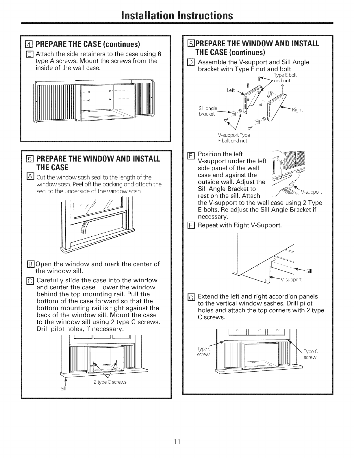
r_ Attach the side retainers to the case using 6
type A screws. Mount the screws from the
inside of the wall case.
[ PREPARETHEWINDOW AND INSTALL
THECASE
[] Cut the window sash seal to the length of the
window sash. Peel off the backing and attach the
seal to the underside of the window sash.
[]PREPARE THEWINDOW AND INSTALL
THECASE(continues)
F_ Assemble the V-support and Sill Angle
bracket with Type F nut and bolt
Type Ebolt
_ nut
Left
Sillangle Right
brocket
V-support Type
F bolt Gndnut
Position the left
D
V-support under the left
side panel of the wall
case and against the
outside wall. Adjust the
Sill Angle Bracket to _pport
rest on the sill. Attach
the V-support to the wall case using 2 Type
E bolts. Re-adjust the Sill Angle Bracket if
necessary.
D
Repeat with Right V-Support.
r_Open the window and mark the center of
the window sill.
[] Carefully slide the case into the window
and center the case. Lower the window
behind the top mounting rail. Pull the
bottom of the case forward so that the
bottom mounting rail is tight against the
back of the window sill. Mount the case
to the window sill using 2 type C screws.
Drill pilot holes, if necessary.
2type Cscrews
Sill
rG] Extend the left and right accordion panels
to the vertical window sashes. Drill pilot
holes and attach the top corners with 2 type
C screws.
I lil JJIll Y"II
Type C
screw
screw
11
JnstaJlationinstructions
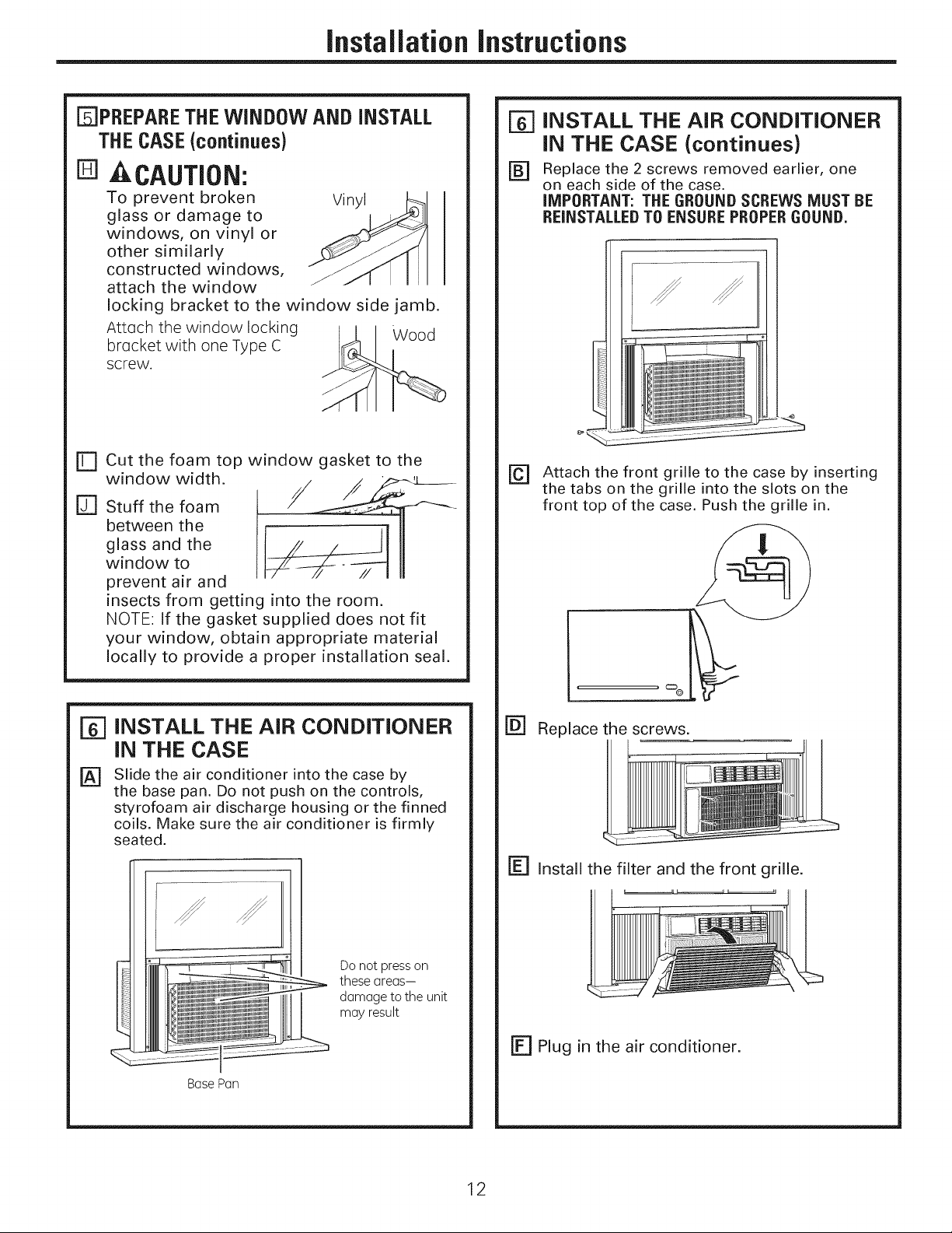
[]PREPARE THEWINDOW AND iNSTALL
THECASE(continues)
In]A CAUTION:
To prevent broken Vinyl
glass or damage to
windows, on vinyl or
other similarly
constructed windows,
attach the window
locking bracket to the window side jamb.
Attach the window locking Wood
bracket with one Type C
screw.
[r] cut the foam top window gasket to the
window width.
r_ stuff the foam
between the
glass and the
window to
prevent air and
insects from getting into the room.
NOTE: If the gasket supplied does not fit
your window, obtain appropriate material
locally to provide a proper installation seal.
[=6]INSTALL THE AIR CONDITIONER
IN THE CASE (continues)
F_ Replace the 2 screws removed earlier, one
on each side of the case.
IMPORTANT: THE GROUNB SCREWS MUST BE
REINSTALLED TO ENSURE PROPERGOUND.
r_ Attach the front grille to the case by inserting
the tabs on the grille into the slots on the
front top of the case. Push the grille in.
r_ INSTALL THE AIR CONDITIONER
IN THE CASE
Slide the air conditioner into the case by
[]
the base pan. Do not push on the controls,
styrofoam air discharge housing or the finned
coils. Make sure the air conditioner is firmly
seated.
Do not presson
these areas-
damage to the unit
may result
Base Pan
_c:D@
F_ Replace the screws.
r_ Install the filter and the front grille.
r_ Plug in the air conditioner.
12
Through-the-Wall Installation Instructions--Optional
The case may be installed through-the-wall
in both existing and new construction.
Read completely, then follow step-by-step.
NOTE: Obtain all materials locally for
mounting the air conditioner through-
the-wall.
[] iMPORTANT
Through-the-wall installation is not
appropriate if any of the side or top louvers
in the case will be obstructed by the wall.
All side and top louvers in the case must
project on the outdoor side of the wall.
The room side of the case must project
into the room far enough to maximize the
balance of the unit.
The case must be installed level from side-
to-side and with a slight tilt from front to
rear. Use a level; no more than a 1/2 bubble
will be the correct case slant to the outside.
Lintel angle is required to support bricks or
blocks above opening.
Flashing is required and should extend the
length of the opening to ensure no inside
cavity leakage occurs.
Remove the air conditioner from the case.
[]
For specific instruction, refer to the Window
Installation Instructions.
[]
Make certain that a wall receptacle is
available close to the hole location or make
arrangements to install a receptacle.
IT] IMPORTANT (cont.)
rD=]Secure with 14 wood screws anchored at
least an inch into the wall support structure.
NOTE: Drill pilot holes, if necessary, for
proper installation. If the frame is oversized,
use shims to prevent case distortion.
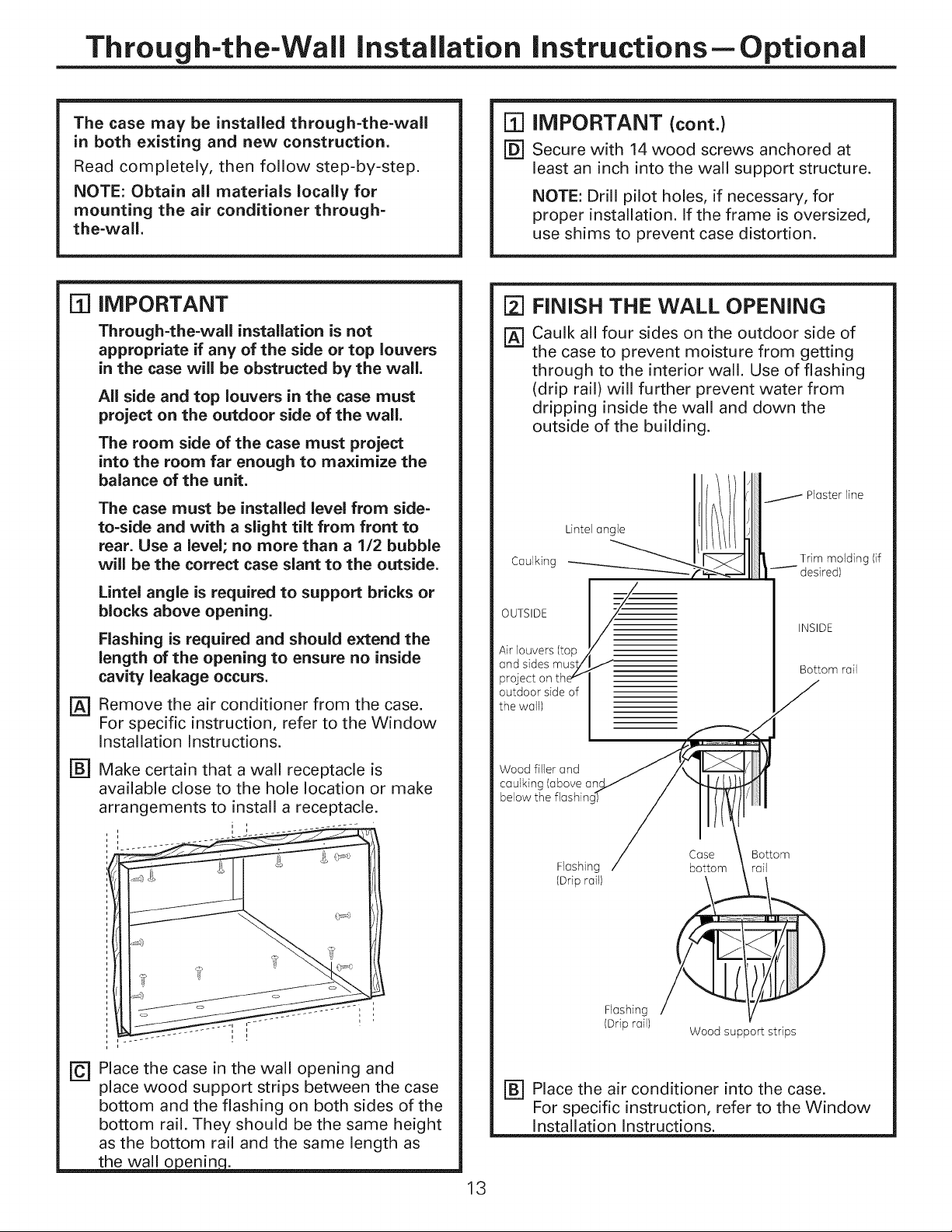
FINISH THE WALL OPENING
Caulk all four sides on the outdoor side of
the case to prevent moisture from getting
through to the interior wall. Use of flashing
(drip rail) will further prevent water from
dripping inside the wall and down the
outside of the building.
Plaster line
Lintel angle
Caulking Trim molding (if
OUTSIDE
Air louvers (top j
and sides mus,t/
project on thev
outdoor side of
the wall)
Wood filler and
caulking (above an
below the flashinc
desired)
INSIDE
Bottom rail
J
F_ Place the case in the wall opening and
place wood support strips between the case
bottom and the flashing on both sides of the
bottom rail. They should be the same height
as the bottom rail and the same length as
Flashing
(Drip rail)
Flashing
(Drip rail)
FB'] Place the air conditioner into the case.
For specific instruction, refer to the Window
Installation Instructions.
Wood support strips
13
Bottom
rail
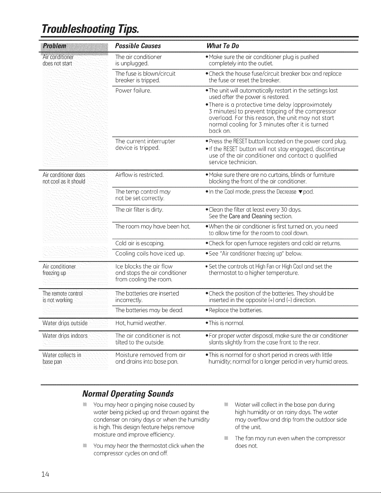
TroubleshootingTips.
Possible Causes What To Do
Theair conditioner * IVlakesurethe air conditioner plug is pushed
doesnotstart isunplugged, completely into the outlet.
Thefuse isblown/circuit *Check the housefuse/circuit breaker box and replace
breaker istripped, the fuse or resetthe breaker.
Power failure. ,The unitwill automatically restart in the settings last
usedafter the power is restored.
•There is a protective time delay (approximately
3 minutes) to prevent tripping of the compressor
overload. For this reason, the unit may not start
normal cooling for 3 minutes after it isturned
back on.
The current interrupter • Pressthe RESETbutton located on the power cord plug.
device istripped. • If the RESETbutton will not stay engaged, discontinue
use of the air conditioner and contact a qualified
service technician.
Airconditionerdoes Airflow is restricted. • Make sure there are no curtains, blindsor furniture
notcoolasit should blocking the front of the air conditioner.
Thetemp control may • In the Coolmode,pressthe DecreaseTpad.
not be set correctly.
Theair filter is dirty. ,Clean the filter at least every 30 days.
Seethe CareandCleaningsection.
Theroom may have been hot. ,When the air conditioner isfirst turned on,you need
to allow time for the room to cool down.
Coldair isescaping. ,Check for open furnace registersand cold air returns.
Cooling coils have iced up. *See "Air conditionerfreezingup"below.
Airconditioner Ice blocks the air flow _Setthe controls at HighFanor HighCooland set the
freezingup and stops the air conditioner thermostat to a higher temperature.
from cooling the room.
Theremotecontrol Thebatteries are inserted ,Check the position of the batteries.They should be
isnotworking incorrectly, inserted in the opposite (+)and (-) direction.
Thebatteries may be dead. • Replacethe batteries.
Water drpsoutside Hot,humid weather. ,This is normal.
Water dripsindoors The air conditioner is not • Forproper water disposal,make sure the air conditioner
tilted to the outside, slants slightly from the case front to the rear.
Wa_ercollects n
basepan
Moisture removed from air
and drains into basepan.
• This isnormal for a short period in areas with little
humidity; normal for a longer period invery humid areas.
Normal Operating Sounds
You may hear a pinging noise caused by
water being picked up and thrown against the
condenser on rainy days or when the humidity
is high.Thisdesign feature helps remove
moisture and improve efficiency.
Vou may hear the thermostat click when the
compressor cycles on and off.
iiiiiiiiiiii_iii
Water will collect inthe base pan during
high humidity or on rainy days.The water
may overflow and drip from the outdoor side
of the unit.
iiiiiiiiiiii_iii
Thefan may run even when the compressor
does not.
14
Notes.15Notes.
16
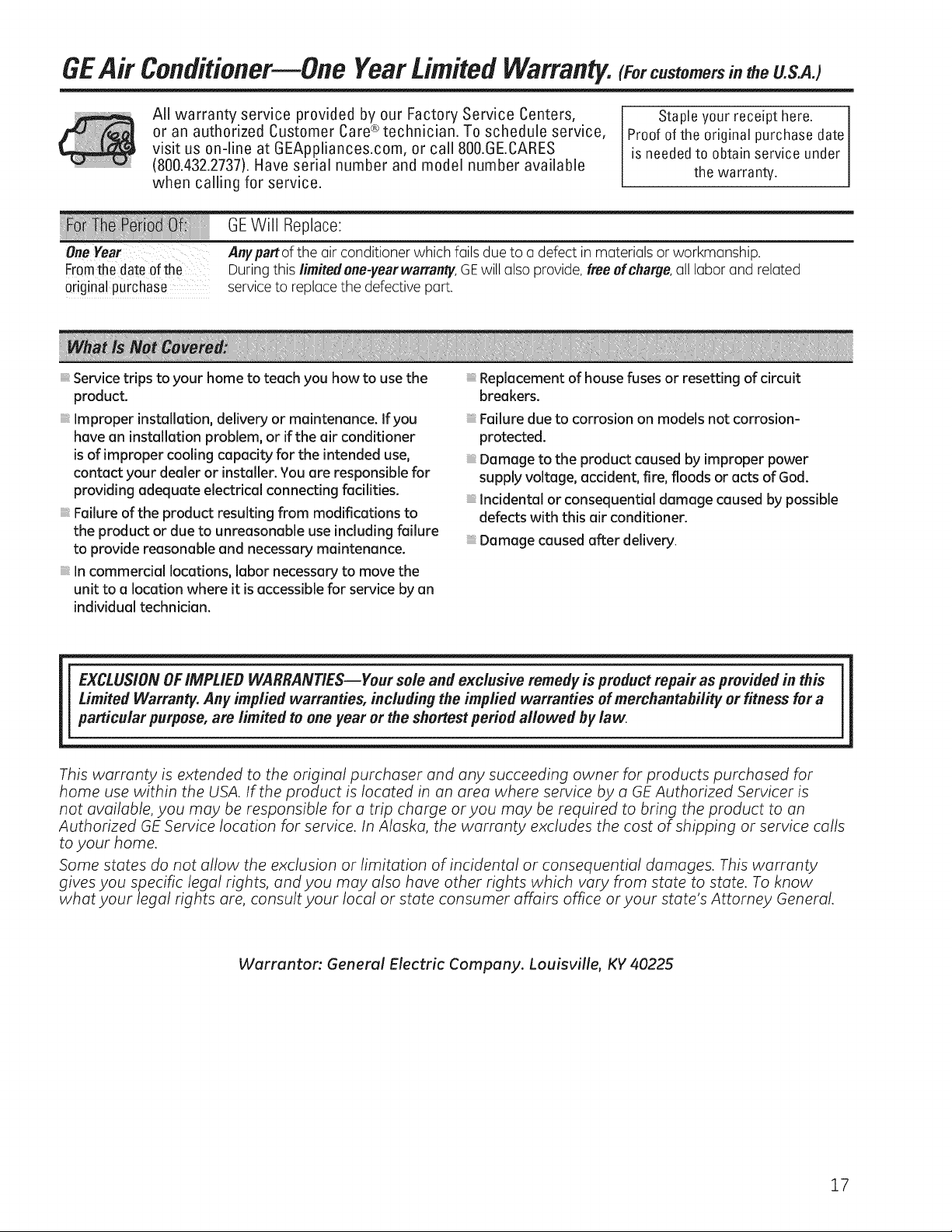
GEAir Conditioner--One YearLimited Warranty. c.stomersi. theU.S.AJ
All warranty service provided by our Factory Service Centers,
or an authorized Customer Care®technician. To schedule service,
visit us on-line at GEAppliances.com, or call 800.GE.CARES
(800.432.2737).Have serial number and model number available
when calling for service.
GEWill Replace:
-_eneYeer
Fromthe dateof the
odginalpurchase
Service trips to your home to teach you how to use the
product.
Improper installation, delivery or maintenance. If you
have an installation problem, or if the air conditioner
is of improper cooling capacity for the intended use,
contact your dealer or installer. You are responsible for
providing adequate electrical connecting facilities.
Failure of the product resulting from modifications to
the product or due to unreasonable use including failure
to provide reasonable and necessary maintenance.
Incommercial locations, labor necessary to move the
unit to a location where it is accessible for service by an
individualtechnician.
Anypartof the air conditioner which fails due to u defect in materials or workmanship.
Duringthis limited one-yearwarranly, GEwill also provide, freeef charge,all labor and related
serviceto replace the defective part.
Staple your receipt here.
Proof of the original purchase date
is needed to obtain service under
the warranty.
Replacement of house fuses or resetting of circuit
breakers.
Failure due to corrosion on models not corrosion-
protected.
Damage to the product caused by improper power
supply voltage, accident, fire, floods or acts of God.
Incidental or consequential damage caused by possible
defects with this air conditioner.
Damage caused after delivery.
EXCLUSION OFIMPLIED WARRANTIES--Your sole and exclusive remedy is product repair as provided in this
Limited Warranty. Any implied warranties, including the implied warranties of merchantability or fitness for a
particular purpose, are limited to one year or the shortest period allowed bylaw.
This warranty is extended to the original purchaser and any succeeding owner for products purchased for
home use within the USA. If the product is located in an area where service by a GE Authorized Servicer is
not available, you may be responsible for a trip charge or you may be required to bring the product to an
Authorized GE Service location for service. In Alaska, the warranty excludes the cost of shipping or service calls
to your home.
Some states do not allow the exclusion or limitation of incidental or consequential damages. This warranty
gives you specific legal rights, and you may also have other rights which vary from state to state. To know
what your legal rights are, consult your local or state consumer affairs office or your state's Attorney General.
Warranton General Electric Company. Louisville, KY 40225
17
 Loading...