


GEAppliances.com
®
Zoneline
Safety Instructions . . . . . . . . . . . . .2
Operating Instructions
Air Direction . . . . . . . . . . . . . . . . . . . . . . . .4
Auxiliary Controls . . . . . . . . . . . . . . . .5–8
Controls . . . . . . . . . . . . . . . . . . . . . . . . . . .3
To Remove the Room Cabinet . . . . . .4
Ventilation Control . . . . . . . . . . . . . . . . .4
Care and Cleaning
Air Filters . . . . . . . . . . . . . . . . . . . . . . . . .10
Base Pan . . . . . . . . . . . . . . . . . . . . . . . . . .9
Outdoor Coils . . . . . . . . . . . . . . . . . . . . . .9
Room Cabinet and Case . . . . . . . . . . . .9
Ventilation Filter . . . . . . . . . . . . . . . . . . . .9
Installation Instructions
Electrical Connection . . . . . . . . . .13–16
Installing the Zoneline . . . . . . . . .17, 18
Optional Drain Kit . . . . . . . . . . . . . . . . .19
Preparation . . . . . . . . . . . . . . . . . . . . . . .11
Replacing an Existing Unit? . . . . . . . .12
Troubleshooting Tips . . . . . .20, 21
Normal Operating Sounds . . . . . . . . .22
Owner’s Manual and
Installation Instructions
Heat/Cool Model 4100
Heat Pump Model 6100
Español
For a Spanish version of this
manual, visit our Website at
www.zoneline.com/literature.
Para consultar una version
en español de este manual
de instrucciones, visite nuestro
sitio de internet
www.zoneline.com/literature.
Français
For a French version of this
manual, visit our Website at
www.zoneline.com/literature.
Pour un version français de
ce manuel d’utilisation, veuillez
visiter notre site web à l’adresse
www.zoneline.com/literature.
Air Conditioners
Consumer Support
Consumer Support . . . . . . . .Back Cover
Warranty . . . . . . . . . . . . . . . . . . . . . . . . .23
Write the model and serial
numbers here:
Model # __________________
Serial # ____________________
Find these numbers on a label
behind the room cabinet on the
base pan.
TINSEA576JBRZ 49-7612 04-09 JR
IMPORTANT SAFETY INFORMATION.
READ ALL INSTRUCTIONS BEFORE USING.
WARNING!
For your safety, the information in this manual must be followed to minimize the risk of fire
or explosion, electric shock, or to prevent property damage, personal injury, or loss of life.
SAFETY PRECAUTIONS
■ This Zoneline must be properly installed
in accordance with the Installation
Instructions before it is used. See the
Installation Instructions in the back
of this manual.
■ Replace immediately all electric service
cords that have become frayed or
otherwise damaged. A damaged power
supply cord must be replaced with a
new power supply cord obtained from
the manufacturer and not repaired.
Do not use a cord that shows cracks
or abrasion damage along its length
or at either the plug or connector end.
■ Unplug or disconnect the Zoneline
at the fuse box or circuit breaker
before making any repairs.
NOTE: We strongly recommend that any
servicing be performed by a qualified
individual.
■ These R410A air conditioning systems
require contractors and technicians to
use tools, equipment and safety
standards approved for use with this
refrigerant. DO NOT use equipment
certified for R22 refrigerant only.
Replacing an existing unit?
For details, see the Installation Instructions
in this manual.
READ AND FOLLOW THISSAFETY INFORMATION CAREFULLY.
SAVE THESE INSTRUCTIONS
Consumer Support Troubleshooting Tips Care and Cleaning Operating Instructions Safety Instructions
2
About the controls on your Zoneline. GEAppliances.com
Safety Instructions Operating Instructions Care and Cleaning Troubleshooting Tips Consumer Support
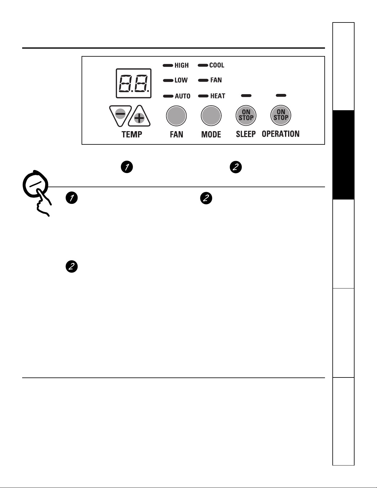
TEMP CONTROL
Controls
Temp Control
The temp control is used to maintain the room
temperature. The compressor will cycle on
and off to keep the room at the same level
of comfort.
Press the pad to raise the temperature.
Press the pad to lower the temperature.
NOTE: The display shows the set temperature,
not the room temperature.
Sleep
Press to set the air conditioner to run for 8 hours
before it automatically returns to the previous
setting.
When in the cooling mode and the sleep timer
is set, the set temperature will automatically
increase 2°F after the second hour then 1°F
each hour over the next two hours. Also, the
fan speed will change to low. When in the
heating mode, the set temperature will
decrease in the same manner.
To cancel the sleep mode, press the MODE pad
or the SLEEP pad a second time.
▲
▼
+
–
FAN, MODE & SLEEP OPERATION
Fan, Mode and Operation Control
FAN—Sets the fan operation for HIGH,
LOW or AUTO speed. When set at AUTO,
it automatically switches between LOW
and HIGH as room temperature changes.
MODE—COOL—For cooling
FAN—For fan-only operation
HEAT—For heating
OPERATION—ON/STOP—Turns the unit
on or off. Power remains connected to
the Zoneline. The Freeze/Heat Sentinel
features still function if active.See the
Freezer/Heat Sentinel section on page 6.
NOTE: The temperature display will flash
to indicate a possible unit malfunction. Set
operation control to STOP and then restart
the unit. If the flashing light reappears within
30 minutes, call for service.
Quick Heat Recovery
Activates each time the thermostat is switched from
STOP or COOL mode to HEAT mode. Electric heaters
are energized until the thermostat set point
is reached. On heat pump models, the heat pump
operation will resume at the next call for heat.
About Your Heat Pump (6100 Series only)
Heat pumps can save money by removing heat
from the outside air—even when the outside
temperature is below freezing—and releasing
that heat indoors.
To get the best performance from your heat pump,
don’t change the room thermostat very often.
Raising the heat setting 2–3 degrees will cause
the Zoneline to use its electric heating elements in
order to reach the new temperature setting quickly.
There is a 3-minute minimum compressor
run time at any setting to prevent short cycling.
The indoor fan motor starts before the compressor
and stops after the compressor cycles off.
When the outdoor temperature is lower than 25°F,
heat is provided by the electric heater in the air
conditioner instead of by the heat pump.
The electric heating elements use much
more electricity than heat pumps and cost
more to operate.
3
Other features of your Zoneline.
Ventilation Control
NOTE: Two shipping screws must be removed
from the vent door before use. See the Installation
Instructions in the back of this manual. If you do not
plan to use the ventilation feature, leave these two
screws in place.
The ventilation control lever is located at
the middle left side of the Zoneline unit,
behind the room cabinet.
When set at the closed position, only the air
inside the room is circulated and filtered.
When set at the open position, some outdoor
air will be drawn into the room. This will reduce
the heating or cooling efficiency.
Energy Tip: Keep the vent control in the closed
position. The room air will be filtered and circulated.
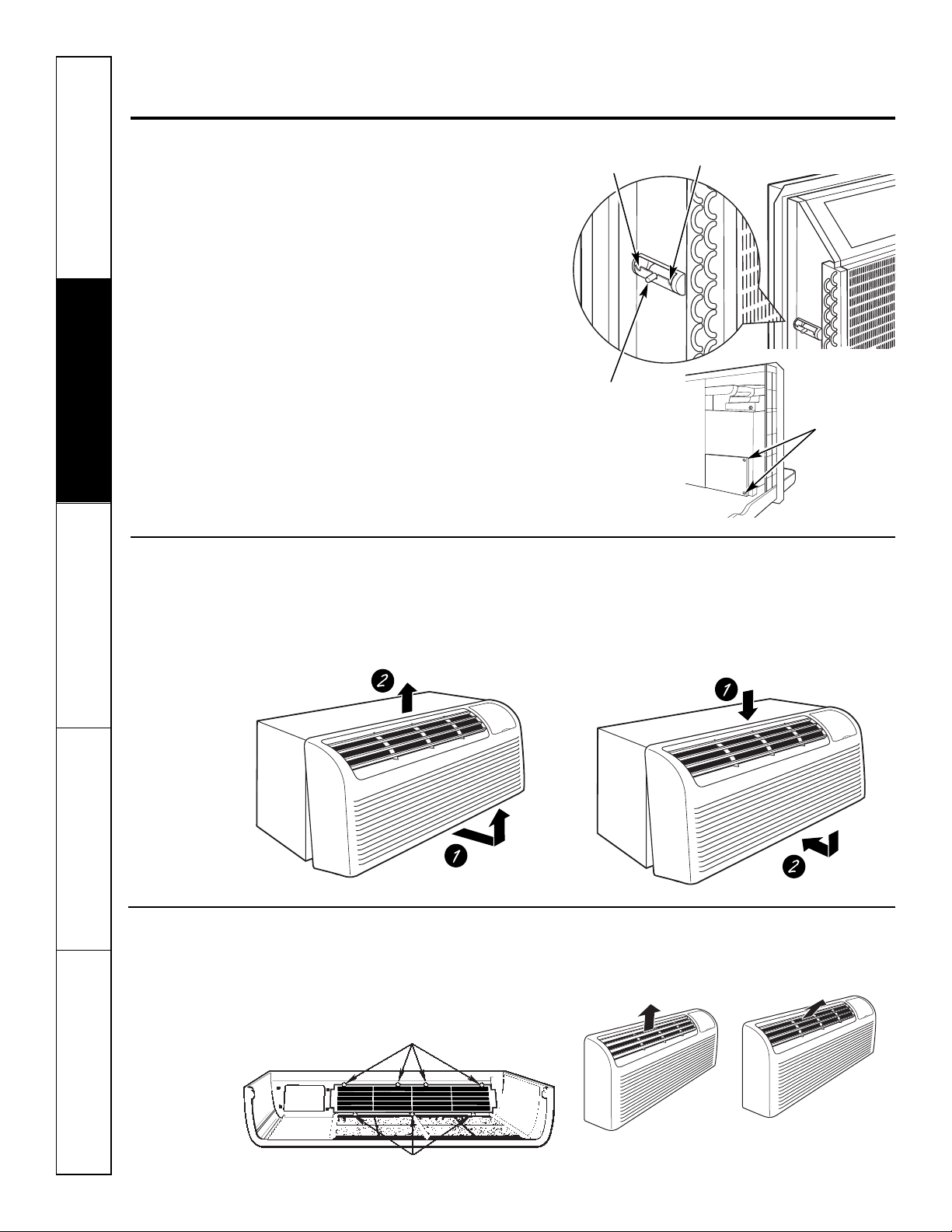
To Remove the Room Cabinet
Additional controls are located behind the
room cabinet.
Open
osition
p
Vent control
(shown in
middle position)
Closed
position
Remove two
shipping screws
(if operation is
desired)
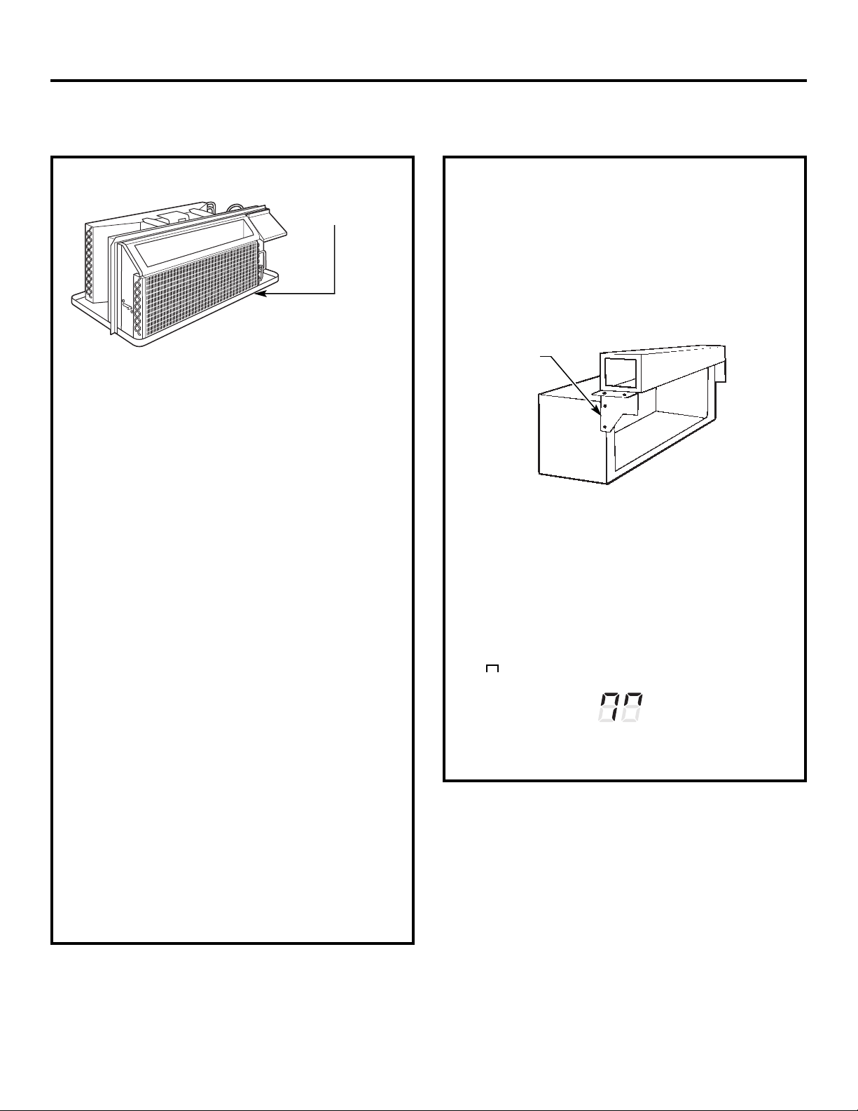
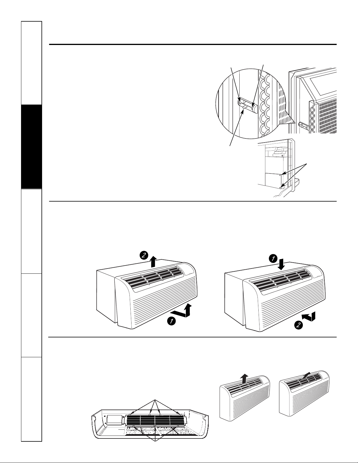
To remove: Pull out at the bottom to release it from
the tabs (1). Then lift up (2).
Air Direction
To change the air direction, remove the room
cabinet. Remove the 7 louver screws that hold
the louver insert in place. Flip the louver insert 180°,
replace the screws and the room cabinet.
Louver screws
To replace: Place the tabs over the top rail (1). Push
inward at the bottom until it snaps into place (2).
Remove the room cabinet and flip the louver
insert to change the air direction.
Default
Consumer Support Troubleshooting Tips Care and Cleaning Operating Instructions Safety Instructions
4
Louver screws
position
Auxiliary controls on your Zoneline. GEAppliances.com
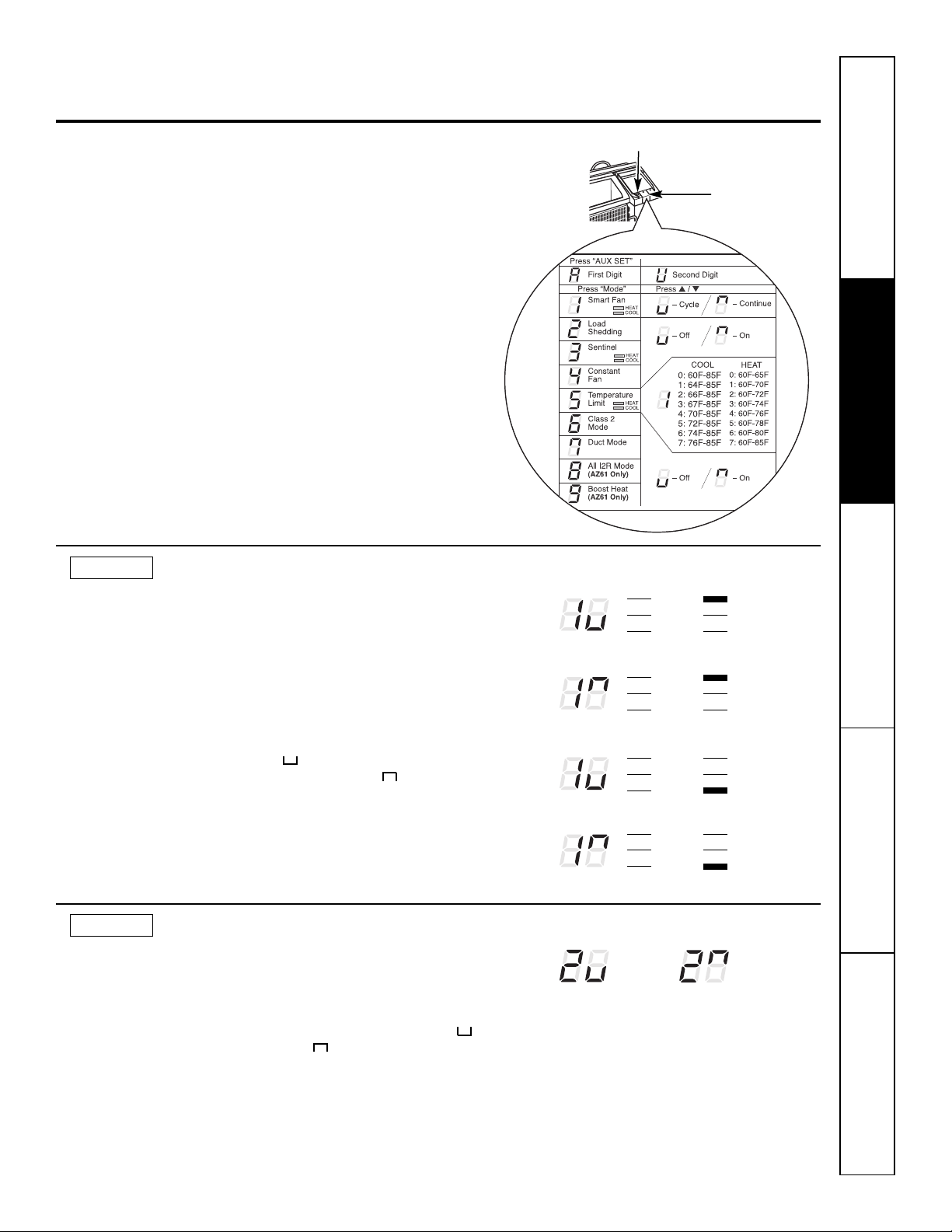
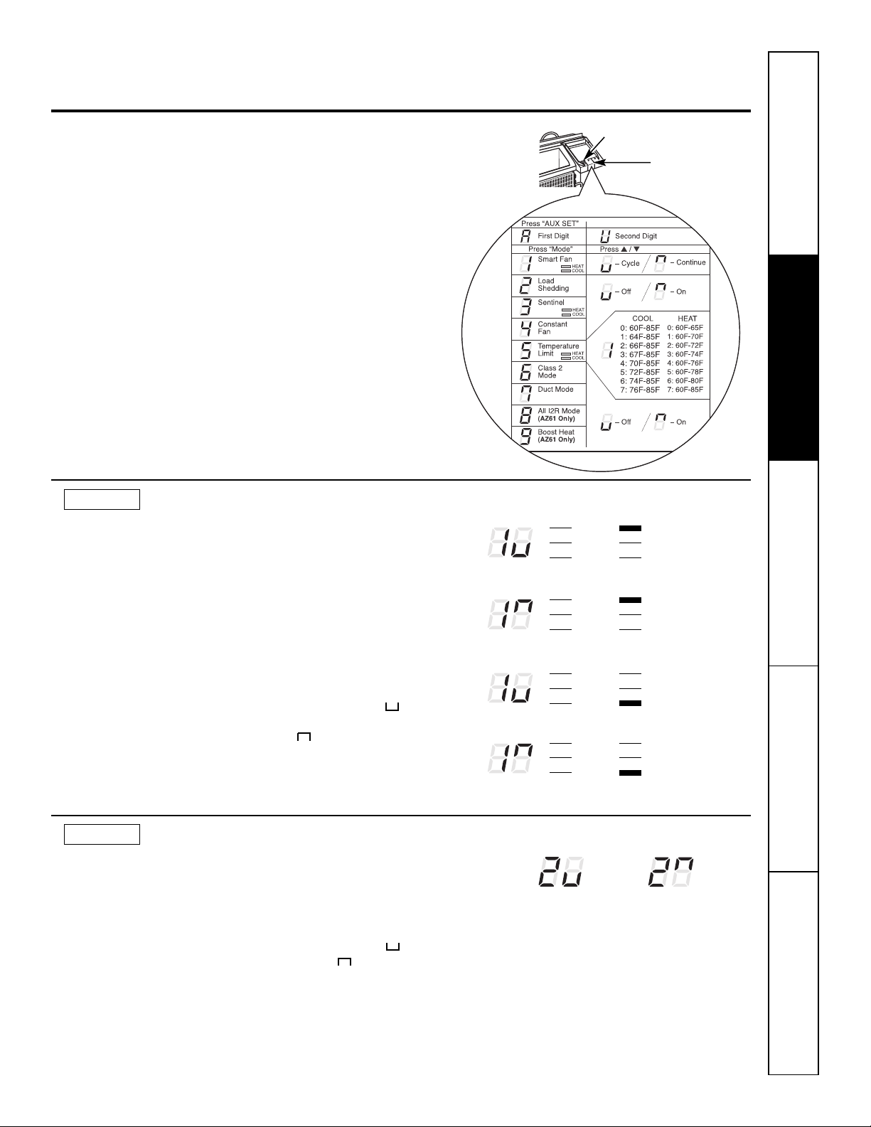
uxiliary Set Button
Auxiliary Controls—Aux Set Button
The auxiliary set controls are located behind
the room cabinet, below the control panel.
Remove the room cabinet. See the To Remove
the Room Cabinet section.
The owner is responsible for ensuring the auxiliary
controls are set to the desired function. There are 9
different modes that can be set using the auxiliary
set button. To change modes, press AUX SET (“AU”
appears on the display). Press the mode button on
the control pad until the first digit in the display
shows the number corresponding to the mode you
are choosing and the correct HEAT/COOL LED is lit.
Press the up or down arrow (shown in the second
digit of the display) to make the mode setting
selection where applicable. Press the AUX SET
button to confirm the selection.
A
Access Cover
Safety Instructions Operating Instructions Care and Cleaning Troubleshooting Tips Consumer Support
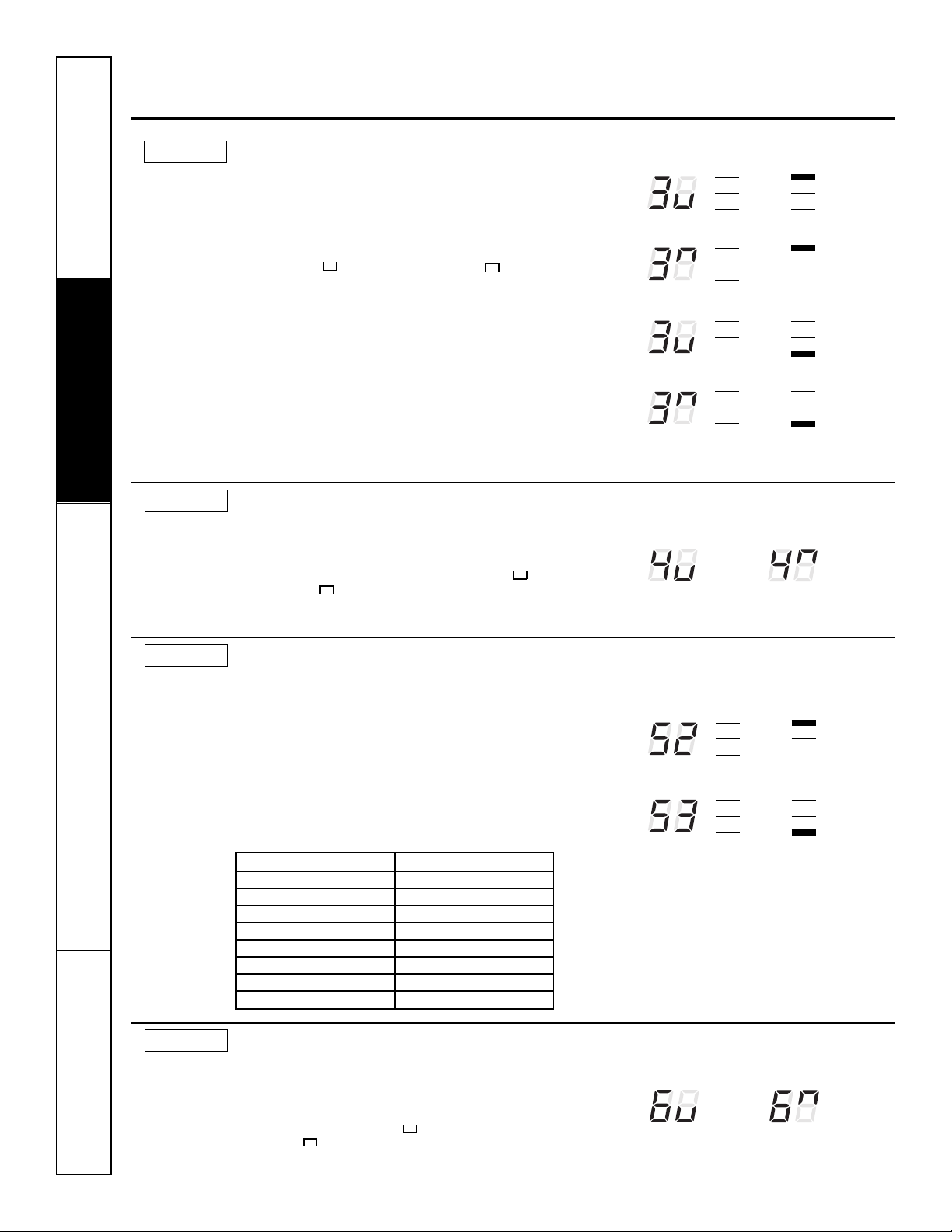
MODE 1
MODE 2
Smart Fan—Cooling/Heating
The default setting for Mode 1 is as follows:
Cooling: Continuous (ON)
Heating: Cycle (OFF)
Press MODE until a 1 appears in the first digit of the
display for Smart Fan cool mode. The COOL LED
light on the main control will be on. To change to
heat mode, press MODE again. The HEAT LED light
on the main control will be lit. Press the down arrow
to set the indoor fan to cycle on/off when the unit is
heating or cooling " ." Press the up arrow to set
the indoor fanto run continuously " ." This is
shown in the second digit of the display. Press AUX
SET to confirm your selection and exit AUX SET
mode, or press MODE to continue setting other
functions.
Load Shedding (Central Desk Control)
The default setting for Mode 2 is OFF.
This feature is active only if the unit is connected to
a CDC and the CDC has control. Press MODE until a
2 appears in the first digit of the display for Load
Shedding mode. Press the down arrow for OFF " "
or the up arrow for ON " ." This is shown in the
second digit of the display. When this mode is on,
only the indoor fan can be turned ON or OFF with
the unit controls. When this mode is off, all
operation is disabled exceptHeat/Freeze Sentinel
(Mode 3). Press AUX SET to confirm your selection
and exit AUX SET mode, or press MODE to continue
setting other functions.
HIGH COOL
LOW FAN
AUTO HEAT
Cooling – Cycle
HIGH COOL
LOW FAN
AUTO HEAT
Cooling – Continuous
HIGH COOL
LOW FAN
AUTO HEAT
Heating – Cycle
HIGH COOL
LOW FAN
AUTO HEAT
Heating – Continuous
Load
Shedding
OFF
Load
Shedding
ON
5
Auxiliary controls on your Zoneline.
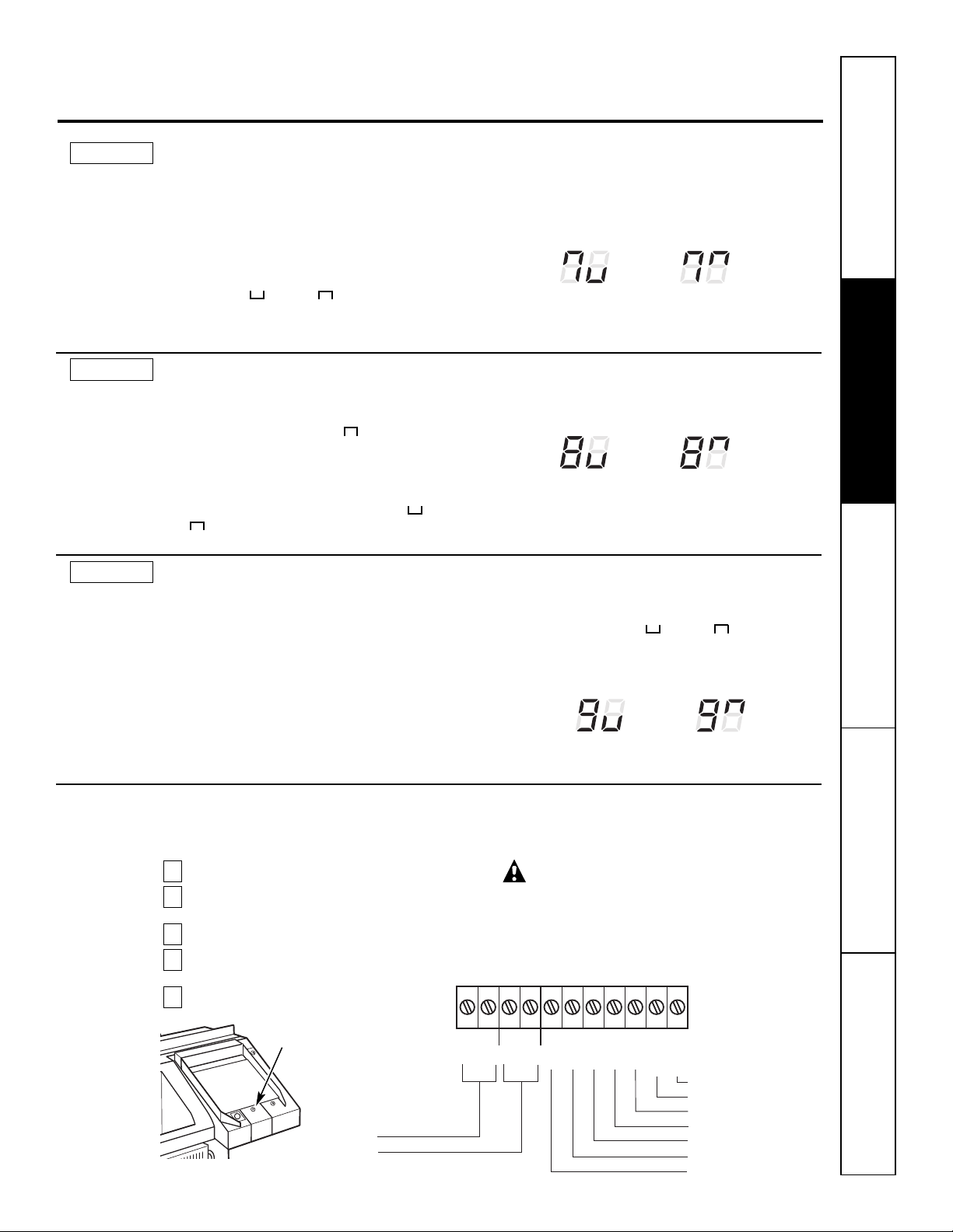
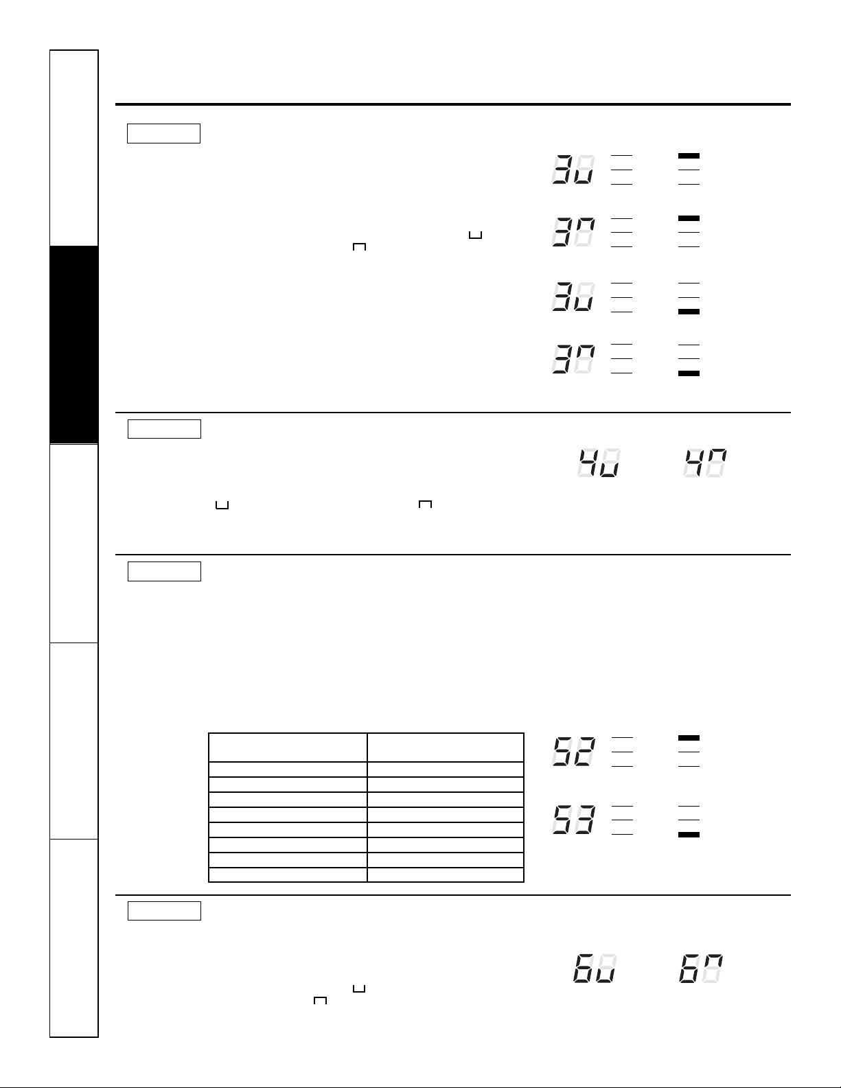
MODE 3
MODE 4
Freeze Sentinel/Heat Sentinel
In the default setting for Mode 3, Heat Sentinel is off, Freeze
entinel is on.
S
Press MODE until a 3 appears in the first digit of the display for
Freeze Sentinel mode. The COOL LEDlight on the main control
will be on. Press MODE again to change to the Heat Sentinel. The
HEAT LED light on the main control will be on. Press the down
arrow for OFF " " or the up arrow for ON " ." This is shown
in the second digit of the display. Press AUX SET to confirm your
selection and exit AUX SET mode, or press MODE to continue
setting other functions.
When Freeze Sentinel is activated, it automatically provides
heat without user interface. This helps to prevent plumbing
damage by turning the heater and indoor fan ON at 41ºF and
OFF at 46ºF.
When Heat Sentinel is activated, it automatically provides
cooling without user interface. This helps to prevent an
excessively hot room by turning the air conditioner ON at 85ºF
and OFF at 80ºF.
NOTE: These functions are active whenever the unit is
plugged in, even if the unit is in the STOP position.
Constant ON Fan
The default setting for Mode 4 is OFF.
Press MODE until a 4 appears in the first digit of the display to set
the fan to run continuously at high speed, even if the unit is in
the STOP position. Press the down arrow for OFF " " or the up
arrow for ON " ." This is shown in the second digit of the
display. Press AUX SET to confirm your selection and exit AUX
SET mode, or press MODE to continue setting other functions.
reeze Sentinel OFF
F
Freeze Sentinel ON
Heat Sentinel OFF
Heat Sentinel ON
Constant
Fan OFF
HIGH COOL
LOW FAN
AUTO HEAT
HIGH COOL
LOW FAN
UTO HEAT
A
IGH COOL
H
LOW FAN
AUTO HEAT
HIGH COOL
LOW FAN
AUTO HEAT
Constant
Fan ON
MODE 5
Temperature Limiting
The default setting for Mode 5 is as follows:
Cool: 0 (60ºF to 85ºF)
Heat: 7 (60ºF to 85ºF)
HIGH COOL
LOW FAN
AUTO HEAT
HIGH COOL
LOW FAN
AUTO HEAT
MODE 6
Press MODE until a 5 appears in the first digit of the display for
Temperature Limiting cool mode. The COOL LEDlight on the
main control will be lit. To change to heat mode, press MODE
again and the HEAT LED light on the main control will be lit. To
set the temperature limits, press the up or down arrow keys. The
second digit of the display will be between 0 and 7 depending on
the limit you want to set. The chart shows the limits available.
Press AUX SET to confirm your selection and exit AUX SET mode,
or press MODE to continue setting other functions.
Temperature limits—Cool Temperature limits—Heat
0 = 60°F to 85°F 0 = 60°F to 65°F
1 = 64°F to 85°F 1 = 60°F to 70°F
2 = 66°F to 85°F 2 = 60°F to 72°F
3 = 68°F to 85°F 3 = 60°F to 74°F
4 = 70°F to 85°F 4 = 60°F to 76°F
5 = 72°F to 85°F 5 = 60°F to 78°F
6 = 74°F to 85°F 6 = 60°F to 80°F
7 = 76°F to 85°F 7 = 60°F to 85°F
Remote Thermostat – Class 2
Temperature Limiting Cool – Limit 2
Temperature Limiting Heat – Limit 3
The default setting for Mode 6 is OFF.
Setting this mode to ON will allow the unit to operate with a Class
2 Remote Control Wall Thermostat. Press MODE until a 6 appears
in the first digit of the display for Class 2 mode. Press the down
Consumer Support Troubleshooting Tips Care and Cleaning Operating Instructions Safety Instructions
6
arrow to turn the option OFF " ." Press the up arrow to turn this
option ON " ." This is shown in the second digit of the display.
Press AUX SET to confirm your selection and exit AUX SET mode,
or press MODE to continue setting other functions.
Class 2 OFF
Class 2 ON
GEAppliances.com
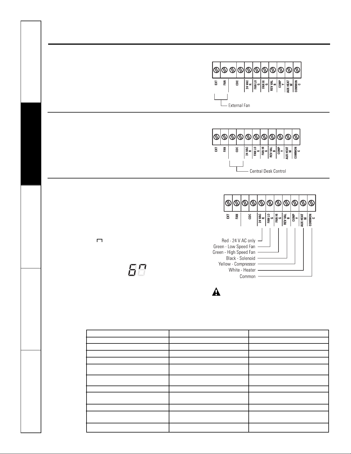
External Fan
Central Desk Control
Common
White - Heater
Yellow - Compressor
Black - Solenoid (AZ61 only)
Green - High Speed Fan
Green - Low Speed Fan
Red - 24 V AC only
EXT
FAN
CDC
24 VAC R
FAN LO G
FAN HI G
REV VAL B
COMP Y
AUX HEAT W
COMMON C
Safety Instructions Operating Instructions Care and Cleaning Troubleshooting Tips Consumer Support
MODE 7
MODE 8
MODE 9
Duct Mode
The default setting for Mode 7 is OFF.
This setting is used when the unit is installed using a
duct adapter kit. If the unit is ducted, the Duct Mode
needs to be set to ON. This increases the fan speed to
ensure proper circulation.
Press MODE until a 7 appears in the first digit of the
display. Press the up or down arrow keys to set this
switch to OFF " " or ON " ." This is shown in the
second digit of the display. Press AUX SET to confirm
your selection and exit AUX SET mode.
All-Electric Heat (AZ6100 only)
The default setting for Mode 8 is OFF.
This electric heat option functions only on the 6100
model. When this option is ON " ," heat pump
operation is locked out, causing the unit to provide
only electric resistance heat.
To set All-Electric Heat option,
appears in the first digit of the display
press MODE until an 8
. Press the up or
down arrow keys to set this switch to OFF " " or
ON " ." This is shown in the second digit of the display.
Heat Boost (AZ6100 only)
The default setting for Mode 9 is OFF.
When Heat Boost is ON and outer temperatures are
between 25ºF and 46ºF, heat pump only operation is
locked out. This setting is used to provide supplementary
heat to the heat pump operation by electric resistance
heat in conditions where the heat pump-only operation
is not sufficient to maintain a consistent, comfortable
room temperature. NOTE: Temperature Boost option
should not be used with remote thermostat operation.
This will cause the unit to switch to resistance heat when
the outdoor temperature is 46ºF.
For Model AZ6100, press MODE to continue setting
other functions. Pressing MODE on Model AZ4100 will
return you to AUX SET mode and an “AU” will appear in
the display.
Duct Mode OFF
Duct Mode ON
Press AUX SET to confirm your selection and exit AUX SET
mode, or press MODE to continue setting other functions.
All-Electric
Heat OFF
All-Electric
Heat ON
To set Heat Boost, press MODE until a 9 appears in the
first digit of the display. Press the up or down arrow keys
to set this switch to OFF " " or ON " ." This is shown
in the second digit of the display. Press AUX SET to
confirm your selection and exit AUX SET mode.
Heat Boost OFF
Heat Boost ON
Auxiliary Controls—Terminal Connections
The auxiliary controls are located behind the room
cabinet beneath the access cover.
Turn off and unplug the unit.
1
Remove the room cabinet. See the To Remove the
2
Room Cabinet section.
Remove the screw from the access cover.
3
To make wiring connections, insert the wires into the
4
bottom of the terminals and tighten screws securely.
After all desired connections have been made,
5
replace the access cover and room cabinet.
Access Cover
The owner is responsible for making all connections and
setting the appropriate AUX SET mode.
CAUTION:
Improper wiring may damage the Zoneline electronics.
No common busing is permitted. Damage or erratic
operation may result. A separate wire pair must be run
from each separate controlling switch to each individual
Zoneline.
7
Auxiliary controls on your Zoneline.
External Fan (Obtained locally)
When connected, an auxiliary or external fan can be
controlled with the indoor fan motor on the Zoneline.
onnections provide 24 V AC to energize a remote relay,
C
turning on the external fan.
Central Desk Control
When connected, the unit can be turned ON or OFF with
a switch located at the Central Control Panel. A separate
wire pair must be run from each separate controlling
switch to each individual Zoneline.
Refer to MODE2 on page 5 for fan setting options.
Remote Thermostat
When connected to a remote thermostat, the indoor air
temperature sensing is shifted from the unit to the
remote thermostat. For this reason, the units will operate
slightly differently when connected to a remote
thermostat. The following chart shows the unit operation
when connected to a remote thermostat.
NOTE: The Class 2 Mode setting (Mode 6) must be set to
ON " " for the unit to operate with a Class 2 Remote
Wall Thermostat. (See the installation instructions
supplied with the remote thermostat and Mode
instructions on page 7.)
Class 2 Shown ON
IMPORTANT: The Zoneline thermostat
connections provide 24 V AConly.
If using a digital/electronic wall thermostat, you must set
it to the 24 V ACsetting. See the Installation Instructions
for the wall thermostat.
Feature Heat Pump Electric Heat
Indoor Frost Control Yes Yes
Freeze Sentinel Yes Yes
Auto Fan Speed No No
Electronic Temperature Limiting No No
Switch to Resistance Heat Based Determined by N/A
On Indoor Temperature Remote Thermostat
Switch to Resistance Heat Based Yes N/A
On Outdoor Temperature
Reverse Cycle Defrost Yes N/A
Simultaneous Resistance Heat No N/A
with Heat Pump
Resistance Heat Lockout Yes N/A
Consumer Support Troubleshooting Tips Care and Cleaning Operating Instructions Safety Instructions
8
“Smart Fan” Fan Cycle Fan ON/AUTO Set On Fan ON/AUTO Set On
Remote Thermostat Remote Thermostat
Central Desk Control Yes Yes
CAUTION:
Damage to a wall thermostat or to the Zoneline
electronics can result from improper connections. Special
care must be used in connecting the wires. No line
voltage connections should be made to any circuit.
Isolate all wires in building from line voltage.
Care and cleaning.
Room Cabinet and Case
Safety Instructions Operating Instructions Care and Cleaning Troubleshooting Tips Consumer Support
urn the Zoneline off and disconnect the
T
power supply.
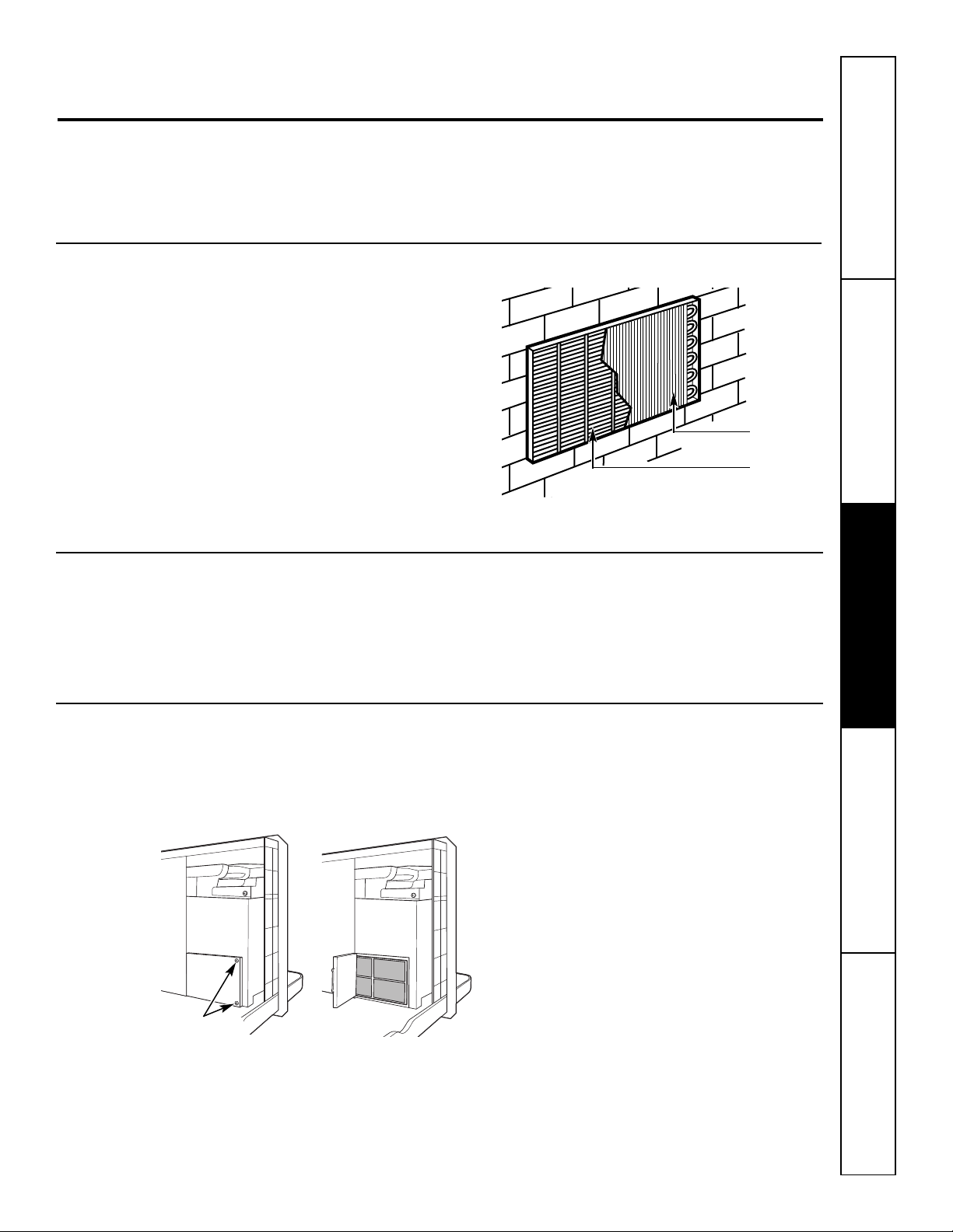
Outdoor Coils
The coils on the outdoor side of the Zoneline should
be checked regularly. If they are clogged with dirt
or soot, they may be professionally steam cleaned.
You will need to remove the unit from the wall
sleeve to inspect the coils. The dirt buildup occurs
on the fan side of the outdoor coil.
Base Pan
In some installations, dirt or other debris may be
blown into the unit from the outside and settle in
the base pan (the bottom of the unit).
o clean, use water and a mild detergent.
T
Do not use bleach or abrasives. Some commercial
cleaners may damage the plastic parts.
Coils
Grille
Clean the outside coils regularly.
In some areas of the United States, a naturally
occurring “gel-like” or “slime-like” substance may
be seen in the base pan.
Ventilation Filter
If the vent door is open, access requires the removal
of the unit from the wall sleeve. Clean the vent filter
twice a year or as required.
Turn the Zoneline off and unplug before cleaning.
Remove two
shipping screws
(if operation is
desired)
Check it periodically and clean, if necessary.
To clean the vent filter:
IMPORTANT:
This filter is not removable. Trying to remove this
filter will damage the unit.
■ Use a vacuum to remove debris from the filter.
■ Use a damp rag to wipe down the filter and
surrounding area after vacuuming.
9

FRONT
FRONT
Care and cleaning.
To maintain optimum performance, clean the filters at least every 30 days.
Air Filters
To remove the air filters:
Pull up
2 Air filters
Dirty filter—Needs cleaning Clogged filter—Greatly
reduces cooling, heating
and airflow.
Turn the Zoneline off before cleaning.
The most important thing you can do to maintain
the Zoneline is to clean the filter at least every
30 days. Clogged filters reduce cooling, heating
and air flow.
Keeping these filters clean will:
■ Decrease cost of operation.
■ Save energy.
■ Prevent clogged heat exchanger coils.
■ Reduce the risk of premature component failure.
To clean the air filters:
■ Vacuum off the heavy soil.
■ Run water through the filters from the
back side.
■ Dry thoroughly before replacing.
NOTE: The air filters are interchangeable
and will fit in either the right or left side.
To replace the air filters:
Push down
CAUTION:Do not operate the
Zoneline without the filters in place. If a filter
becomes torn or damaged, it should be replaced
immediately.
Operating without the filters in place or with
damaged filters will allow dirt and dust to reach
the indoor coil and reduce the cooling, heating,
airflow and efficiency of the unit.
Replacement filters are available from your
salesperson, GE dealer, GE Service and Parts
Center or authorized Customer Care®servicers.
Consumer Support Troubleshooting Tips Care and Cleaning Operating Instructions Safety Instructions
10
Installation Zoneline Air
Instructions Conditioners
Questions? Call 800.GE.CARES (800.432.2737) or Visit our Website at: GEAppliances.com
BEFORE YOU BEGIN
Read these instructions completely and carefully.
•
IMPORTANT – Save these instructions for
local inspector’s use.
•
IMPORTANT – Observe all governing
codes and ordinances.
• Note to Installer – Be sure to leave these
instructions with the owner.
• Note to Owner – Keep these instructions for
future reference.
• Proper installation is the responsibility of the installer.
• Product failure due to improper installation is not
covered under the Warranty.
TOOLS YOU WILL NEED
Phillips screwdriver
IMPORTANT ELECTRICAL
SAFETY—READ CAREFULLY
CAUTION:
• Follow the National Electrical Code (NEC) or local
codes and ordinances.
• For personal safety, this Zoneline must be properly
grounded.
• Protective devices (fuses or circuit breakers)
acceptable for Zoneline installations are specified
on the nameplate of each unit.
• Do not use an extension cord with this unit.
• Aluminum building wiring may present special
problems—consult a qualified electrician.
• When the unit is in the OFF position, there is
still voltage to the electrical controls.
• Disconnect the power to the unit before
servicing by:
1 Removing the power cord (if it has one) from
the wall receptacle.
OR
2 Removing the branch circuit fuses or turning
the circuit breakers off at the panel.
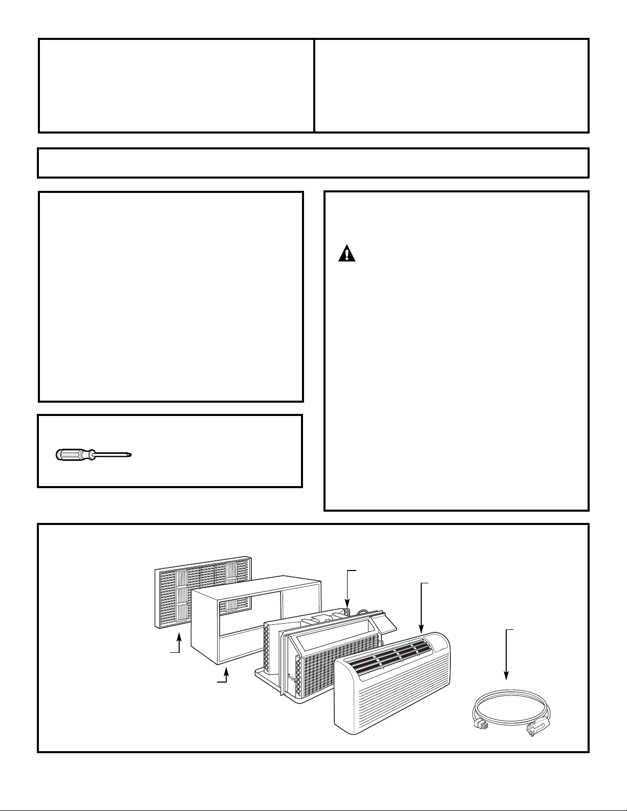
ZONELINE COMPONENTS
Appearance may vary.
Exterior grille/louver**
Wall case**
** Shipped with the Zoneline unit
** Check the “Essential Elements” list on the unit located on front of the base pan
11
Zoneline unit
Room cabinet*
Power supply kit**
Installation Instructions
REPLACING AN EXISTING UNIT?
Check the “Essential
Elements” label for
important information.
Use the correct wall case
This unit is designed to be installed in a GE plastic or
insulated metal wall case. This minimizes condensation
from forming on the room side of the case.
If the current wall case is not insulated, you can reduce
the possibility of condensation forming by installing
insulation kit RAK901L, available where you purchased
the unit.
NOTE: There are several extra holes in the unit side flanges
for installation in wall cases other than GE. To avoid
damaging the flange insulation, the installer should use
an awl or other sharp tool to puncture the insulation in
the appropriate holes before installing the attachment
screws.
Use the correct outdoor grille
You should use the outdoor grilles shown on the
“Essential Elements” label on the base pan.
• If an existing grille is not replaced, capacity and
efficiency will be reduced and the unit may fail to
operate properly or fail prematurely. A deflector kit,
RAK40, may be used with grilles that were not designed
for your new GE Zonelines. The RAK40 contains air
deflectors and gaskets that mount to the unit to direct
the hot exhaust air away from the air intake to allow
the unit to function properly. The grille must have a
65% minimum free area.
• Any vertical deflectors in the existing rear grille should
be removed to decrease condenser air recirculation
that can cause the unit to “short-cycle” and lead to
premature component failure.
Replacing a ducted unit
New ducted installation:
If this unit is to be installed in a new ducted application
using a duct adapter kit, the kit must be installed before
the unit is placed in the wall case. The installation
instructions are packed with the kit.
Duct kits available:
RAK6052
RAK601/602
Mounting
plate
Existing ducted installation:
Replacement of an existing ducted unit may require
different components. Request this information from your
sales representative.
• Replacing 230/208 volt units:
See page 13.
• Replacing 265 volt units:
See page 14.
When using a duct kit, you must always turn Mode 7 to
ON " ." See Mode instructions on page 7.
Duct Mode
Shown ON
Duct
Case
Use the correct power cord
Local codes may require the use of arc fault or leakage
current detection devices on 230/208-volt installations.
12
Installation Instructions
230/208 VOLT ELECTRICAL CONNECTION OPTIONS
HOW TO CONNECT
1. Remove the room cabinet.
2. Connect to electrical power.
3. Review the following steps for applicable supply
voltages.
4. Reinstall the room cabinet.
Power cords may include an arc fault interruption
r a leakage current detection interruption device.
o
A test and reset button is provided on the plug case
or the inline case. The device should be tested on
a periodic basis by first pressing the TEST button
and then the RESET button. If the TEST button does
not trip or if the RESET button will not stay engaged,
discontinue use of the Zoneline and contact a
qualified service technician.
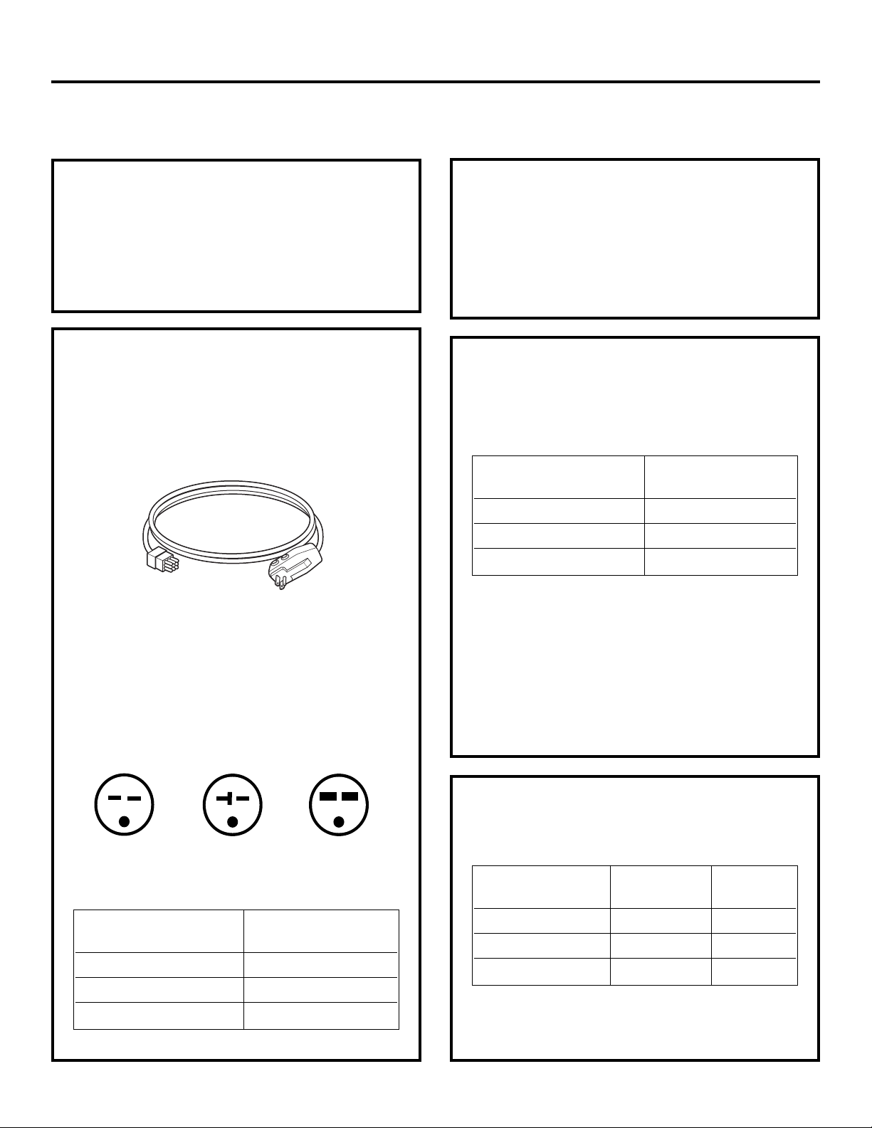
POWER CORD
CONNECTION
A power supply kit withLCDI must be used to supply power
to the Zoneline unit. The appropriatekit isdetermined by
the voltage, the means of electrical connection and
the amperage of the branch circuit.
Appearance may vary.
Power supply kit
Connections of 208 or 230-volt circuits may be with a
power supply kit or a junction box kit.
All wiring, including installation of the receptacle, must
be in accordance with the NEC and local codes,
ordinances and regulations. Codes require the use of
an arc fault or leakage current detection device on the
power cord except direct connect. Be sure to select the
correct cord for your installation.
ELECTRICAL SUBBASE
CONNECTION
230/208-volt models may be installed using one
of the following electrical subbases:
Branch Circuit and Proper GE
Unit Amperage Rating Subbase Kit
15 RAK204D15P
20 RAK204D20P
30 RAK204D30P*
*Not approved for use on 7000 BTUmodels.
Electrical subbases provide an enclosure for direct
connection or enclosed receptacles. The subbase kit
includes the power cord.
The instructions provided with the selected subbase kit
must be carefully followed. It is the responsibility of the
installer to ensure the connection of components is done
in accordance with these instructions and all electrical
codes.
Tandem
15 Amp.
230/208-volt receptacle configuration.
Branch Circuit and Proper GE Power Cord
Unit Amperage Rating with LCDI Device
*Not approved for use on 7000 BTU models.
Perpendicular
20 Amp.
15 RAK3153
20 RAK3203
30 RAK3303*
Large Tandem
30 Amp.
DIRECT CONNECTION
Order the following Kit for 230/208-volt direct
connection as required:
Branch Circuit and Power Supply Power
Unit Amperage Rating Accessory Supply Kit
15 RAK4002A RAK4157
20 RAK4002A RAK4207
30 RAK4002A RAK4307*
*Not approved for use on 7000 BTU models.
Skip to the “MAKE ELECTRICAL CONNECTION TO THE UNIT”
section.
13
Installation Instructions
265 VOLT ELECTRICAL CONNECTION OPTIONS
WARNING:
onnection of this 265V AC product to a branch circuit
C
MUST be done by direct connection in accordance with
the National Electrical Code. Plugging this unit into a
building-mounted exposed receptacle is not permitted
by code.
These models must be installed using the appropriate
GE power supply kit for the branch circuit amperage and
the electrical resistance heater wattage desired. Use the
POWER CONNECTION CHART on page 16 to determine
the correct kit required. One of the following installation
methods (A or B) must be used.
A. FOR SUBBASE INSTALLATION
Electrical subbase kits are available to provide a flexible
enclosure for direct connection.
Branch Circuit and Proper GE Power
Unit Amperage Rating Subbase Kit Supply Kit
15 RAK204E15 RAK5172
20 RAK204E20 RAK5202
B. FOR DIRECT CONNECT
INSTALLATION
If an electrical subbase is not used, direct connection to
branch circuit wiring inside the provided junction box must
be done in accordance with the following steps.
Order the following Kit for 265-volt direct connection
as required:
Branch Circuit and Power
Unit Amperage Rating Supply Kit
15 RAK5157
20 RAK5207
30 RAK5307*
*Not approved for use on 7000 BTUmodels.
Proceed to the “MAKE ELECTRICAL CONNECTION TO THE
UNIT” section.
NOTE: Order Kit RAK4002CW to enable a quick
disconnect inside the junction box.
30 RAK204E30 RAK5302*
*Not approved for use on 7000 BTUmodels.
The instructions provided with the selected subbase kit
must be carefully followed. It is the responsibility of the
installer to ensure the connection of components is done
in accordance with these instructions and all electrical
codes.
14
Installation Instructions
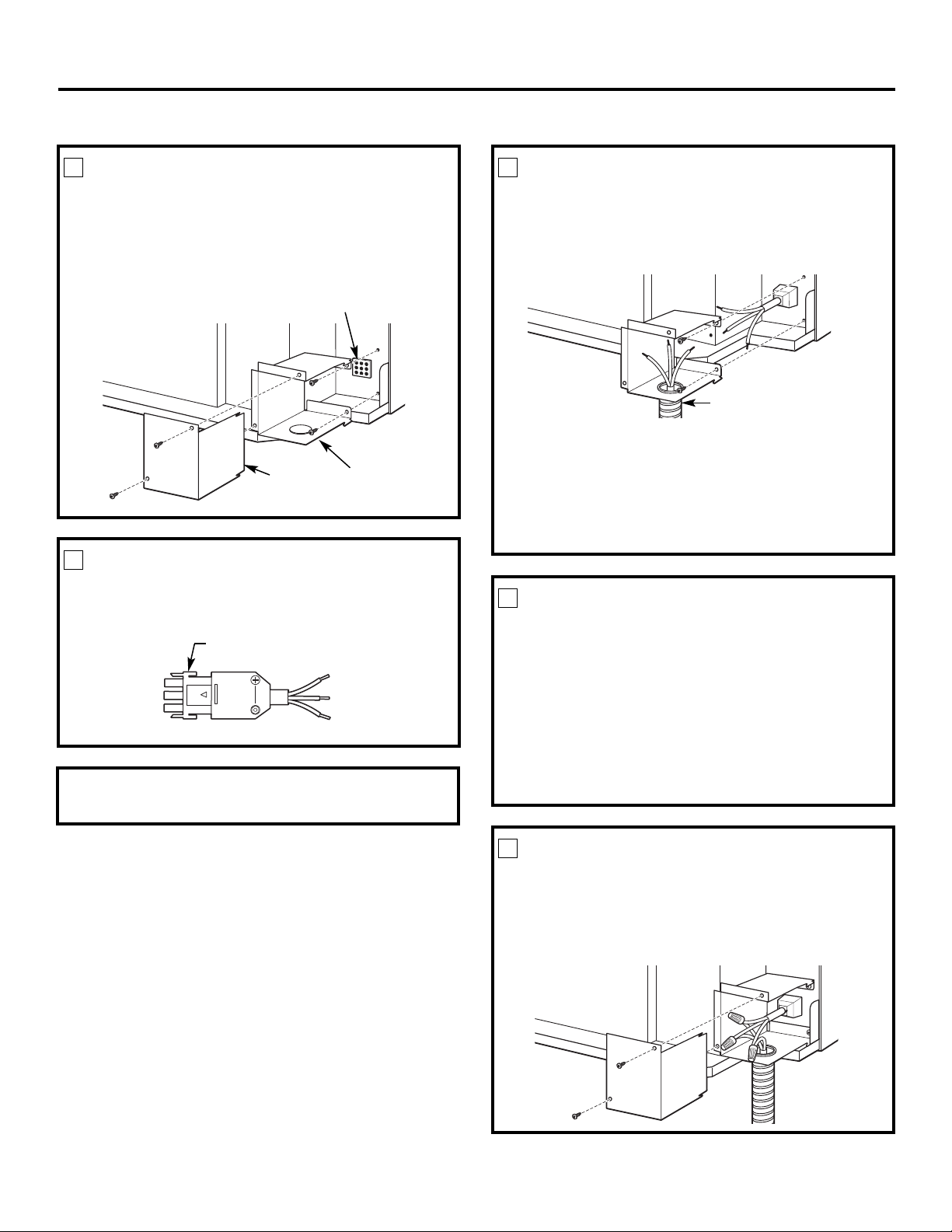
MAKE ELECTRICAL CONNECTION TO THE UNIT
1
REMOVE JUNCTION BOX
1. Remove the junction box cover by removing the front
two screws.
2. Remove the junction box by removing the top and
bottom rear screws. Note how the tabs on the lower
left side of the junction box serve to hold the side in
place. This will help when the box is being reinstalled.
Unit connector
Junction
box cover
2
CONNECT THE CORDSET
Plug the connector, provided in the Direct Connect Kit,
fully into place in the unit mating connector. Be sure
the locking tabs at the sides are engaged.
Connector
NOTE: Order Kit RAK4002CW to enable a quick
disconnect inside the junction box.
Junction
box
3
ATTACH CONDUIT
1. Use the round knockout at the bottom of the junction
box to attach conduit coming from the branch circuit.
Remove the knockout, attach the conduit and bring
wires into the junction box. Leave 6″ of wire free at the
end of the conduit to allow connections to be made.
Conduit
2. If a fuse and fuseholder are to be used, the
knockout at the top of the box is for mounting
a Buss fuseholder. Be sure the fuse and fuseholder are
of the same rating as the branch circuit. Leadwires at
the fuse can be either soldered in place or attached
using UL-listed 1/4″ female (receptacle) crimp
connectors. Follow local codes.
4
REINSTALL JUNCTION BOX
• Reinstall the junction box by engaging the left tabs
on the lower right face of the unit, aligning the screw
holes at the top and bottom and driving the two
screws until secure. Be sure that all wire leads are
inside the box and not pinched between the box and
the unit. The green insulated ground wire from the unit
MUST be connected to the branch circuit ground wire.
Make all wire connections by using appropriate
UL-listed electrical connectors and techniques
(black to black, white to white and green to green).
15
5
REINSTALL JUNCTION BOX COVER
1. Carefully tuck all wires and connections back inside
the junction box. Be sure there are no loose
connections or stray uninsulated wires exposed.
2. Place the junction box cover in place. Replace the two
screws removed earlier and tighten securely.
Installation Instructions
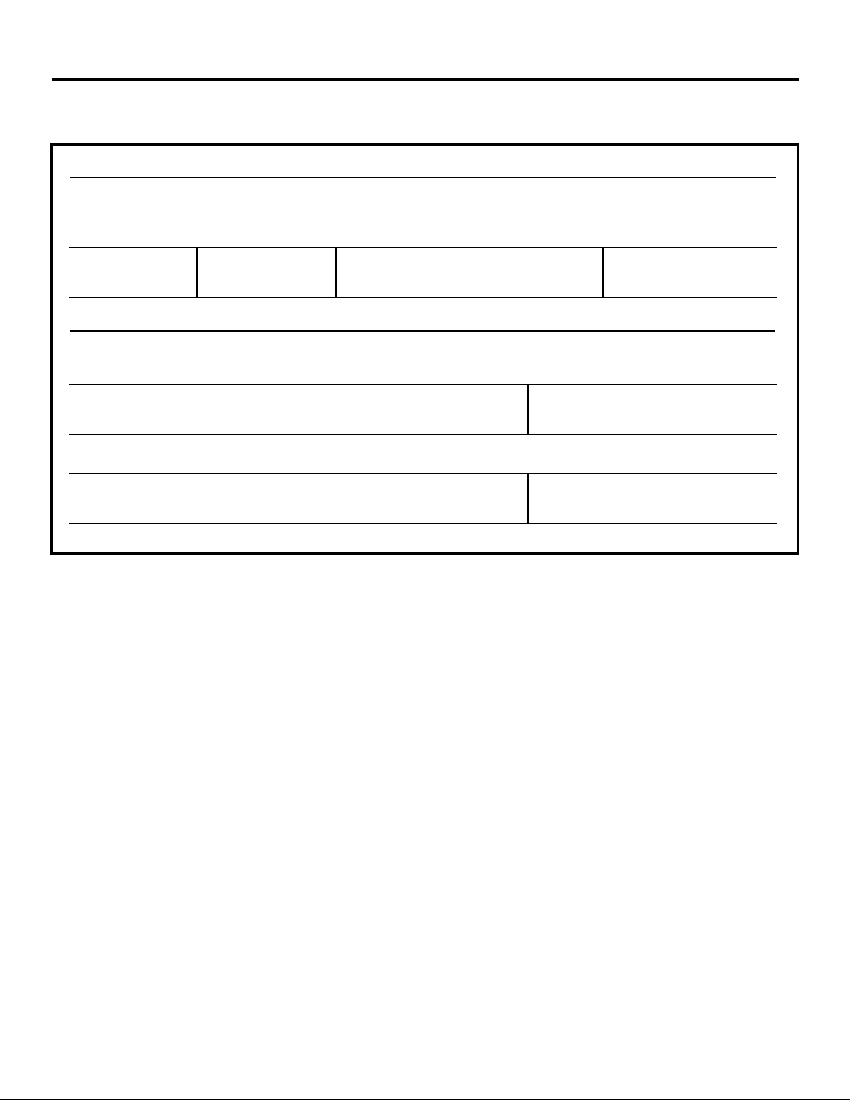
POWER CONNECTION CHART
Power Cord Connections
230/208 Volt
Power Supply Kits
with Current Leakage Wall Plug Heater Wattage
Detection Device Configuration Circuit Protective Device @ 230/208 Volts
RAK3153 Tandem 15-Amp Time-Delay Fuse or Breaker 2.55/2.09 KW
RAK3203 Perpendicular 20-Amp Time-Delay Fuse or Breaker 3.45/2.82 KW
RAK3303* Large Tandem 30-Amp Time-Delay Fuse or Breaker 5.00/4.10 KW
Direct Connections
230/208 Volt Heater Wattage
Power Supply Kits Circuit Protective Device @ 230/208 Volts
RAK4157 15-Amp Time-Delay Fuse or Breaker 2.55 KW/2.09 KW
RAK4207 20-Amp Time-Delay Fuse or Breaker 3.45 KW/2.82 KW
RAK4307* 30-Amp Time-Delay Fuse or Breaker 5.00 KW/4.10 KW
265 Volt Heater Wattage
Power Supply Kits Circuit Protective Device @ 265 Volts
RAK5157 15-Amp Time-Delay Fuse or Breaker 2.55 KW
RAK5207 20-Amp Time-Delay Fuse or Breaker 3.45 KW
RAK5307* 30-Amp Time-Delay Fuse or Breaker 5.00 KW
*Not approved for use on 7000 BTUH units.
16
Installation Instructions
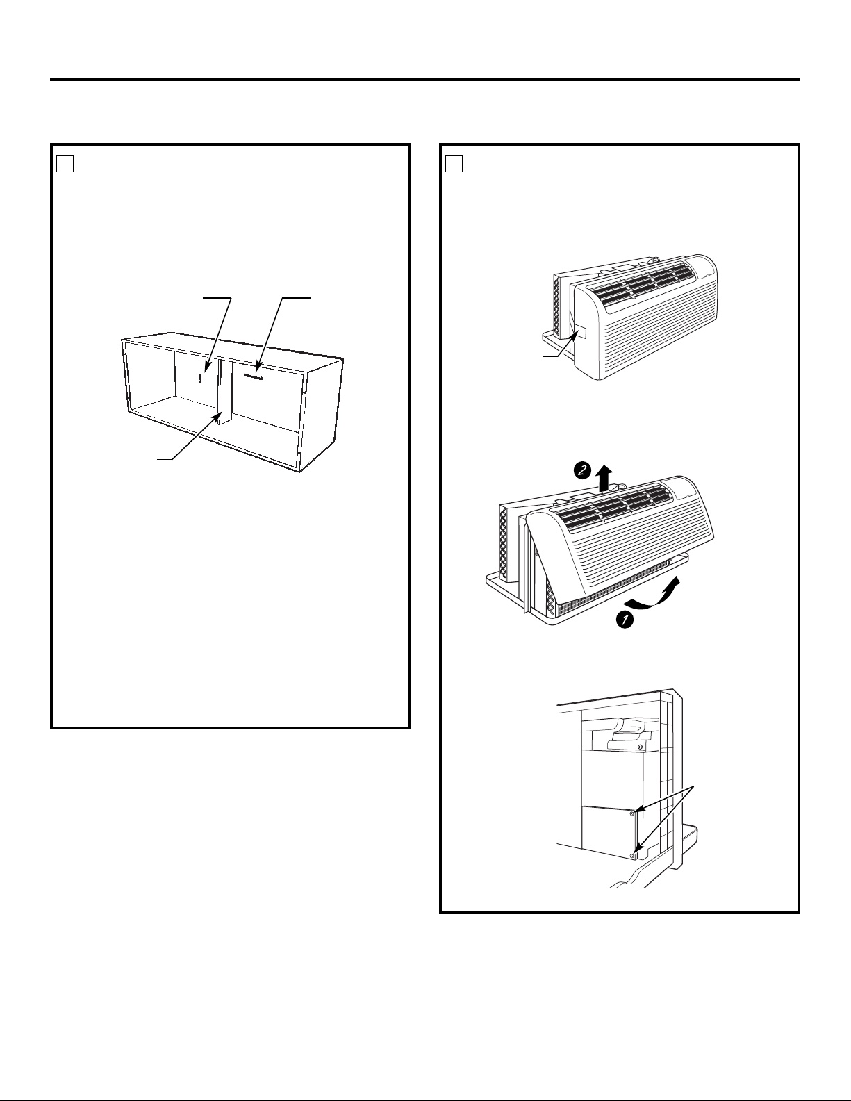
INSTALLING THE ZONELINE
1
INSTALL THE WALL CASE AND
EXTERIOR GRILLE
The RAB71A series or RAB77A4 wall case must be
properly installed per instructions packed with the case.
• Remove the corrugated stiffener and the outdoor
protective panel. Use the slit in the outdoor panel
as a handhold and push out.
Protective
panel
Stiffener
• Install the exterior grille from the room side following
instructions packed with the grille.
Insulated Wall Case
This unit is designed to be installed in a GE plastic
or an insulated steel wall case. This minimizes
condensation from forming on the room side of
the case.
The RAB71A series wall cases are insulated. Insulation kit
RAK901L is available for use with RAB77A4 or existing
uninsulated wall cases when needed.
NOTE: For installation with a subbase or duct adapter,
see the instructions packed with those kits.
Slit
2
PREPARE THE UNIT
• Carefully remove shipping tape and foam shipping
blocks from the room cabinet, compressor and
vent door. There may be multiple blocks and pieces
of shipping tape that need to be removed.
Shipping tape
(Locations may vary)
• Remove the room cabinet by pulling it out at the
bottom to release it (1); then lift it up to clear the rail
along the unit top (2).
• If vent door is to be operational, remove shippingscrews
from the front side of the vent door, if present.
17
Remove two
shipping screws
(if operation is
desired)
Installation Instructions
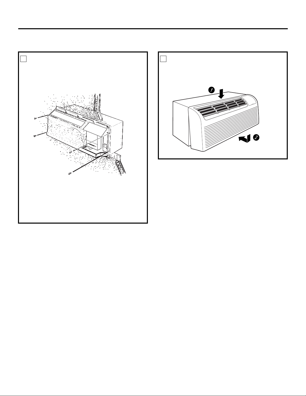
INSTALLING THE ZONELINE (cont.)
3
INSTALL THE UNIT INTO THE
WALL CASE
lide the unit into the wall case and secure with four
S
screws through the unit flange holes.
NOTE: There are several extra holes in the unit side
flanges for installation in wall cases other than GE.
To avoid damaging the flange insulation, the installer
should use an awl or other sharp tool to puncture the
insulation in the appropriate holes before installing the
attachment screws.
4
REPLACE THE ROOM CABINET
einstall the room cabinet by hooking the top over
R
the rail along the unit top (1), then pushing it in at
the bottom (2).
18
Installation Instructions
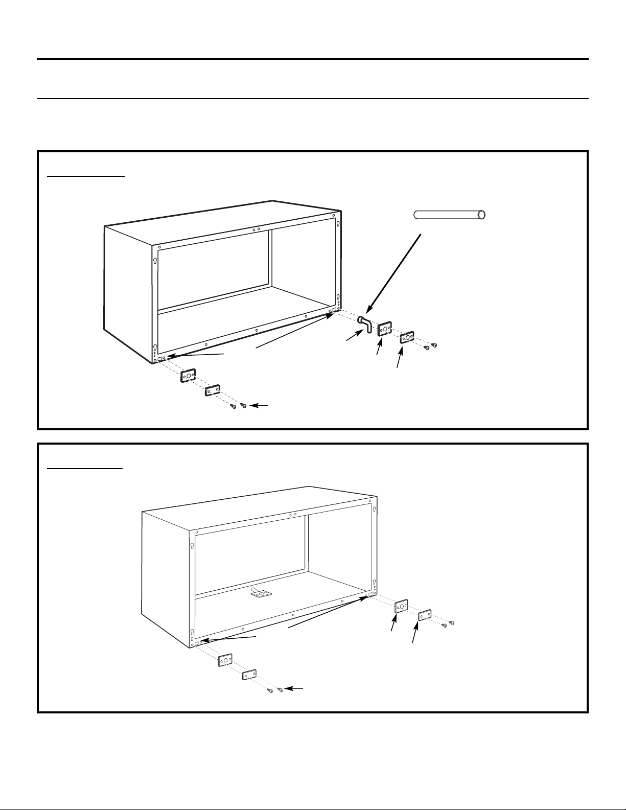
OPTIONAL—DRAIN KIT INSTALLATION
Dry Air 25 Series models are designed to improve dehumidification by 25%. Since more moisture will be removed from
the air, there is a greater possibility that water will drip from the wall case than with a standard unit. To prevent this
water from dripping onto external building walls, we recommend the use of RAD10 Drain Kit .
External Drain
See the Installation Instructions
in the RAD10 kit.
Alternate:
6″ long, 1/2″ O.D. straight
copper tube
1/2″ O.D. drain tube
Square drain holes
Neoprene sponge gasket
Steel mounting plate
Internal Drain
See the Installation Instructions in
the RAD10 kit .
Type “A” screw for metal case or
Type “B” screw for molded case
(The drain is located
under the cabinet)
Square drain holes
Neoprene sponge gasket
Type “A” screw for metal case or
Type “B” screw for molded case
Steel mounting plate
19
Before you call for service…
Troubleshooting Tips
Save time and money! Review the charts on the
following pages first and you may not need to call for
service.
Problem Possible Causes What To Do
Zoneline does The unit is • Make sure the Zoneline plug is pushed completely
not start unplugged. into the outlet.
The power cord is not • Remove the room cabinet and make sure that the
firmly attached. yellow connector on the end of the power cord is
firmly engaged.
The fuse is blown/circuit • Check the house fuse/circuit breaker box and replace
breaker is tripped. the fuse or reset the breaker.
The unit is waiting for • This is normal. The Zoneline will start again after
the compressor overload it resets.
protector to reset.
Power failure. • If power failure occurs, set the mode control to STOP.
When power is restored, set the mode control to the
desired setting.
• There is a protective time delay (up to 3 minutes) to
prevent tripping of the compressor overload. For this
reason, the unit may not start normal heating or cooling
for 3 minutes after it is turned back on.
The current interrupter • Press the RESET button located on the power cord plug
device is tripped. or the box near the plug.
• If the RESET button will not stay engaged,discontinue use
of the Zoneline and contacta qualified service technician.
Zoneline does not cool Indoor airflow • Make sure there are no curtains, blinds or furniture
or heat as it should is restricted. blocking the front of the Zoneline.
Outdoor airflow is • Make sure the rear grille is not restricted. This can
restricted or recirculated. cause the unit to cycle off due to the compressor
overload protector.
• Outdoor grille must have a minimum of 65% free area.
Non-GE grilles may be too restrictive for proper
performance. Consult your salesperson for assistance.
The temp control may • Turn the control to a lower or higher setting.
not be set properly. NOTE: The temperature limiter may belimiting the
temperature range.
The air filter is dirty. • Clean the filter at least every 30 days.
See the Operating Instructions section.
The room may have • When the Zoneline is first turned on you need to
been hot or cold. allow time for the room to cool down or warm up.
Outdoor air is • Set the vent control to the closed position.
entering the room.
Burning odoratthe start Dust is on the surface • This can cause a “burning” odor at the beginning of
of heating operation of the heating element . the heating operation. This odor should quickly fade.
Consumer Support Troubleshooting Tips Care and Cleaning Operating Instructions Safety Instructions
20

GEAppliances.com
Problem Possible Causes What To Do
The air is not always The heat pump is not • This is normal. The heat pump will produce warm air
cool or hot during producing hot air. but not as hot as air produced when the higher-cost
operation electric heat is used.
The Smart Fan Auxiliary • This causes the fan to blow room temperature air
Controls may be set to even when the compressor or heater cycles off.
continuous fan. The continuous air movement provides better
overall temperature control in the cool mode.
See Smart Fan – Cooling/Heating on page 5.
The air does not feel The heat pump alone • Use the Electric Heat Option. This turns off the
warm enough during produces air that feels heat pump and warms with electric heat only.
heating operation cooler than desired. NOTE: Use of this option will result in increased energy
consumption.
The unit is not The Smart Fan Auxiliary • See Smart Fan – Cooling/Heating on page 5.
blowing out air Controls may be set to cycle.
The electric heating The power cord is not • Remove the room cabinet and make sure that the
feature does not work firmly attached. yellow connector on the end of the power cord is
firmly engaged.
Safety Instructions Operating Instructions Care and Cleaning Troubleshooting Tips Consumer Support
Temperature display The compressor may • Set the operation control to STOP and then restart
flashes have failed. the unit . If the flashing light reappears within
30 minutes, call for service.
21
Things that are normal.
Normal Operating Sounds
“CLICK”
You may hear a pinging noise caused by water being
picked up and thrown against the condenser on rainy
days or when the humidity is high. This design feature
helps remove moisture and improve efficiency.
You may hear relays click when the controls cycle
on and off or are adjusted to change the room
temperature.
Water will collect in the base pan during high humidity
or on rainy days. The water may overflow and drip
from the outdoor side of the unit.
The indoor fan runs continuously when the unit is
operating in the cooling mode, unless the Smart Fan
Auxiliary Control is set to cycle. This will cause the fan
to cycle on and off with the compressor. You may also
hear a fan noise stop and start.
3-Minute
Delay
SILENCE
COMPRESSOR
PROTECTION
You may notice a few minutes delay in starting if you
try to restart the Zoneline too soon after turning it
off or if you adjust the thermostat right after the
compressor has shut off. This is due to a built-in
restart protector for the compressor that causes
a 3-minute delay.
During the defrost cycle, both indoor and outdoor fans
stop and the compressor will operate in the cooling
mode to remove frost from the outdoor coil. After
defrost, the unit will restart in electric heat to quickly
warm the room to the desired comfort level.
To protect the compressor and prevent short cycling,
the unit is designed to run for a minimum of 3 minutes
after the compressor starts at any thermostat setting.
Consumer Support Troubleshooting Tips Care and Cleaning Operating Instructions Safety Instructions
22
Zoneline Warranty.
Safety Instructions Operating Instructions Care and Cleaning Troubleshooting Tips Consumer Support
All warranty service provided by our Factory Service Centers
or an authorized Customer Care
®
technician. To schedule service,
on-line, visit us at GEAppliances.com, or call 800.GE.CARES
(800.432.2737). For service in Canada, contact Gordon Williams
Corp. at 1.888.209.0999. Please have serial number and model
Staple your receipt here.
Proof of the original purchase
ate is needed to obtain service
d
under the warranty.
number available when calling for service.
For The Period Of: GE Will Replace:
One Year Any part of the Zoneline which fails due to a defect in materials or workmanship. During this
From the date of the limited one-year warranty, GE will also provide, free of charge, all labor and related service to
original purchase replace the defective part.
Five Years Any part of the sealed refrigerating system (the compressor, condenser, evaporator and all
From the date of the connecting tubing) which fails due to a defect in materials or workmanship. During this
original purchase four-year limited additional warranty, GE will also provide, free of charge, all labor and
related service to replace the defective part.
Five Years For the second through the fifth year from the date of original purchase, GE will replace
From the date of the certain parts that fail due to a defect in materials or workmanship. Parts covered are fan
original purchase motors, switches, thermostats, heater, heater protectors, compressor overload, solenoids,
circuit boards, auxiliary controls, thermistors, frost controls, ICR pump, capacitors, varistors
and indoor blower bearing. During this four-year limited additional warranty, you will be
responsible for any labor or on-site service costs.
What GE Will Not Cover:
■ Service trips to your site to teach you how to use
the product.
■ Improper installation, delivery or maintenance.
■ If you have an installation problem, or if the air
conditioner is of improper cooling capacity for the
intended use, contact your dealer or installer. You
are responsible for providing adequate electrical
connecting facilities.
■ In commercial locations, labor necessary to move the
unit to a location where it is accessible for service by
an individual technician.
■ Failure or damage resulting from corrosion due to
installation in an environment containing corrosive
chemicals.
■ Replacement of fuses or resetting of circuit breakers.
EXCLUSION OF IMPLIED WARRANTIES—Your sole and exclusive remedy is product repair as provided in this Limited
Warranty. Any implied warranties, including the implied warranties of merchantability or fitness for a particular
purpose, are limited to one year or the shortest period allowed by law.
■ Failure of the product resulting from modifications
to the product or due to unreasonable use, including
failureto provide reasonable and necessary
maintenance.
■ Failure or damage resulting from corrosion due
to installation in a coastal environment, except
for models treated with special factory-applied
anti-corrosion protection as designated in
the model number.
■ Damage to product caused by improper power supply
voltage, accident, fire, floods or acts of God.
■ Incidentalor consequential damageto personalproperty
caused by possible defects with this air conditioner.
■ Damage caused after delivery.
■ Product not accessible to provide required service.
This warranty is extended to the original purchaser and any succeeding owner for products purchased
for use within the USA and Canada. If the product is located in an area where service by a GE Authorized
Servicer is not available, you may be responsible for a trip charge or you may be required to bring the
product to an Authorized GE Service location for service. In Alaska, the warranty excludes the cost of
shipping or service calls to your site.
Some states or provinces do not allow the exclusion or limitation of incidental or consequential damages.
This warranty gives you specific legal rights, and you may also have other rights which vary from state
to state or province to province. To know what your legal rights are, consult your local, state or provincial
consumer affairs office or your state’s Attorney General.
Warrantor: General Electric Company. Louisville, KY 40225
23

Consumer Support.
GE Appliances Website
Have a question or need assistance with your appliance? Try the GE Appliances Website 24 hours a day,
ny day of the year! For greater convenience and faster service, you can now download Owner’s Manuals,
a
order parts or even schedule service on-line.
GEAppliances.com
Schedule Service GEAppliances.com
Expert GE repair service is only one step away from your door. Get on-line and schedule your service at
your convenience any day of the year! Or call 800.GE.CARES (800.432.2737) during normal business hours.
Real Life Design Studio GEAppliances.com
GE supports the Universal Design concept—products, services and environments that can be used by
people of all ages, sizes and capabilities. We recognize the need to design for a wide range of physical and
mental abilities and impairments. For details of GE’s Universal Design applications, including kitchen design ideas
for people with disabilities, check out our Website today. For the hearing impaired, please call 800.TDD.GEAC
(800.833.4322).
Parts and Accessories GEAppliances.com
Individuals qualified to service their own appliances can have parts or accessories sent directly to their homes
(VISA, MasterCard and Discover cards are accepted). Order on-line today, 24 hours every day or by phone at
800.626.2002 during normal business hours.
Instructions contained in this manual cover procedures to be performed by any user. Other servicing
generally should be referred to qualified service personnel. Caution must be exercised, since improper
servicing may cause unsafe operation.
Contact Us GEAppliances.com
If you are not satisfied with the service you receive from GE, contact us on our Website with all the details
including your phone number, or write to: General Manager, Customer Relations
GE Appliances, Appliance Park
Louisville, KY 40225
Register Your Appliance GEAppliances.com
Register your new appliance on-line—at your convenience! Timely product registration will allow for
enhanced communication and prompt service under the terms of your warranty, should the need arise.
You may also mail in the pre-printed registration card included in the packing material.
Printed in China

www.electromenagersge.ca
®
Zoneline
Mesures de sécurité . . . . . . . . . . . . . . . . . . . . . .2
Fonctionnement
Commandes . . . . . . . . . . . . . . . . . . . . . . . . . . . . .3
Commandes auxiliaires . . . . . . . . . . . . . . . .5–8
Commande de ventilation . . . . . . . . . . . . . . . .4
Direction de l’air . . . . . . . . . . . . . . . . . . . . . . . . . .4
Enlèvement de la carrosserie
côté chambre . . . . . . . . . . . . . . . . . . . . . . . . . . . .4
Entretien et nettoyage
Carrosserie et boîtier côté chambre . . . . . . .9
Filtre de ventilation . . . . . . . . . . . . . . . . . . . . . . .9
Filtres à air . . . . . . . . . . . . . . . . . . . . . . . . . . . . .10
Plateau . . . . . . . . . . . . . . . . . . . . . . . . . . . . . . . . . .9
Serpentin extérieur . . . . . . . . . . . . . . . . . . . . . . .9
Instructions d’installation
Branchement électrique . . . . . . . . . . . . .13–16
Installation de votre Zoneline . . . . . . . .17, 18
Préparation . . . . . . . . . . . . . . . . . . . . . . . . . . . . .11
Remise en place
d’un appareil existant? . . . . . . . . . . . . . . . . . .12
Trousse de drainage en option . . . . . . . . . .19
Manuel d’utilisation et
instructions d’installation
Modèle à réchauffement/
rafraîchessment 4100
Modèle de pompe
à chaleur 6100
Conseils de dépannage . . . . . . . . .20, 21
Bruits normaux de fonctionnement . . . . . .22
Soutien au consommateur
Garantie . . . . . . . . . . . . . . . . . . . . . . . . . . . . . . . .23
Soutien au
consommateur . . . . . . . . . . . . . . . . . . . . . . . . . .24
Transcrivez les numéros de
modèle et de série ici :
# de modèle__________________
# de série ____________________
Trouvez ces numéros sur
une étiquette placée derrière
la carrosserie côté chambre,
sur le plateau.
Conditionneur d’air
TINSEA576JBRZ 49-7612-1F 07-09 JR
MESURES DE SÉCURITÉ IMPORTANTES.
LISEZ D’ABORD TOUTES LES DIRECTIVES.
AVERTISSEMENT!
Pour votre sécurité, suivez les directives fournies dans le présent manuel afin de minimiser
les risques d’incendie, d’explosion et de chocs électriques et prévenir des dégâts matériels
et des blessures graves ou mortelles.
MESURESDESÉCURITÉ
■ Vous devez bien installer votre Zoneline,
conformément aux Instructions
d’installation, avant de l’utiliser. Consultez
les Instructions d’installation à l’arrière de
ce manuel.
■ Remplacez immédiatement tout cordon
d’alimentation abîmé ou endommagé.
Un cordon d’alimentation électrique
endommagé ne doit pas être réparé mais
plutôt remplacé par un autre cordon
d’alimentation obtenu du fabricant.
N’utilisez pas un cordon d’alimentation
qui montre des fissures ou des signes
d’abrasion sur sa longueur ou encore
près de la prise ou du connecteur.
■ Débranchez ou enlevez la fiche de votre
Zoneline au niveau du coffret à fusibles
ou du disjoncteur avant de le réparer.
NOTE : Nous vous recommandons vivement
de confier toute réparation à un technicien
qualifié.
■ Pour les systèmes de climatisation
au R410A, il est nécessaire que les
entrepreneurs et les techniciens utilisent
des outils, un équipement et des normes
de sécurité autorisés pour ce fluide
frigorigène. N’utilisez PAS d’équipement
certifié pour le fluide frigorigène R22.
Remise en place d’un appareil
existant?
Pour de plus amples détails, consultez les
Instructions d’installation dans ce manuel.
VEUILLEZ LIRE ET SUIVRE ATTENTIVEMENT
CES MESURES DE SÉCURITÉ.
CONSERVEZ CES DIRECTIVES
Soutien au consommateur Conseils de dépannage Entretien et nettoyage Fonctionnement Mesures de sécurité
2

Les commandes de votre Zoneline. www.electromenagersge.ca
Mesures de sécurité Fonctionnement Entretien et nettoyage Conseils de dépannage Soutien au consommateur
COMMANDE DE
TEMPÉRATURE
Commandes
Commande de température
La commande de température est utilisée pour
régler la température de la pièce. Le compresseur
se mettra en marche de façon sporadique de
manière à maintenir le niveau de confort de
la pièce.
+
Appuyez sur le bouton pour élever
la température.
Appuyez sur le bouton pour abaisser
la température.
NOTE: L’afficheur indique la température reglée,
pas la température de la pièce.
Veille
Appuyezpoureffectuerunréglagetemporaired’une
durée de8 heuresavantque l’appareil nerevienne à
son réglageinitial.
Lorsque l’appareilest enmodeclimatisation
et que le chronomètrede veille estsélectionné,
la température réglée s’élèvera automatiquement
de 1,1 °C (2°F) après la deuxième heure et de 0,6°C
(1 °F) à chacunedes deux heuressuivantes. En plus,
le ventilateur serèglera à basse vitesse. Lorsqu’il
est en mode chauffage, la température réglée
s’abaissera dela façon décrite précédemment.
Pour annuler le mode de veille, appuyez
sur le bouton MODE ou appuyez de nouveau
sur le bouton SLEEP (veille).
▲
–
▼
FONCTIONNEMENT DU
VENTILATEUR, MODE ET VEILLE
Ventilateur, mode et commande
de fonctionnement
VENTILATEUR—Règle le fonctionnement
duventilateur selon les vitesses HIGH (élevée), LOW
(basse) ouAUTO.Lorsqueréglé à AUTO,la vitesse
change de élevée à basse selon les changements
de température de la pièce.
MODE—COOL—Pour climatisation
FAN—Pour le fonctionnement
du ventilateur seulement
HEAT—Pour le chauffage
FONCTIONNEMENT—ON/STOP—Met en marche
ou éteint l’appareil. Le Zoneline demeure sous
tension. Les fonctions Freeze/Heat Sentinel (garde
gel/chaleur) fonctionnent toujours si ce dernier est
activé. Consultez la section Garde de gel/Garde de
chaleur à la page 6.
NOTE: L’afficheur de température clignoterapour
indiquerunedéfaillance possible.Réglez lacommande
defonctionnement à STOPpuis redémarrezl’appareil.
Siletémoin clignotantréapparaîtdans les 30minutes
qui suivent, appelezunréparateur.
Récupération rapide de la chaleur
S’active à chaque fois que le thermostat est passé
du mode STOP (arrêt) ou COOL (froid) au mode HEAT
(chaleur). Les radiateurs électriques sont alimentés
jusqu’à ce que le point de réglage du thermostat
soit atteint. Sur les modèles à pompe à chaleur,
le fonctionnement de la pompe à chaleur reprendra
au prochain appel de chaleur.
Votre pompe à chaleur (Série 6100 uniquement)
Les pompes à chaleur peuvent vous faire économiser
de l’argent en tirant la chaleur de l’air extérieur—même
quand la température extérieure est inférieure au gel—et
en libérant cette chaleur à l’intérieur.
Pour obtenir un bon rendement de votre pompeà
chaleur, ne changez pas souvent le réglage du
thermostat de la chambre. Si vous augmentez de 2 ou 3
degrés la température désirée, votre Zoneline utilisera
ses éléments de chauffage électrique pour atteindre
rapidement la nouvelle température que vous avez
choisie.
Le compresseur doit fonctionner au moins trois minutes
à n’importe quel réglage pouréviter un fonctionnement
avec arrêts et remises en marche répétés.
Le moteur du ventilateur intérieur commence avant la
mise en marche du compresseur et s’arrête après l’arrêt
du compresseur, à la fin du cycle.
Lorsque la température extérieure est inférieure à
-3,8 °C (25 °F), la chaleur produite provient de l’élément
chauffant électrique du conditionneur plutôt que de
la pompe à chaleur.
Les éléments de chauffage électrique utilisent beaucoup
plus d’électricité que les pompes à chaleur et coûtent
davantage à l’usage.
3
Autres caractéristiques de votre Zoneline.
Commande de ventilation
NOTE : Vous devez enlever de la porte de ventilation
deux vis d’expédition avant d’utiliser votre appareil.
Consultez les Instructions d’installation à l’arrière du
présent manuel. Si vous envisagez de ne pas utiliser
la fonction de ventilation, laissez ces deux visen
place.
Le levier de commande de la ventilation est situé
au milieu du côté gauche de l’unité Zoneline à
l’arrière de la carrosserie côté chambre.
Quand il est réglé en position fermé, seulement
l’air à l’intérieur de la chambre circule et est filtré.
Quand il est réglé en position ouvert, un peu d’air
de l’extérieur entre dans la chambre. Cela réduit
l’efficacité de chauffage ou de rafraîchissement
de votre appareil.
Pour économiser l’énergie, placez la commande
de ventilation en position fermé. L’air de la chambre
sera filtré et circulera.
Enlèvement de la carrosserie côté chambre
Des commandes additionnelles se trouvent derrière
la carrosserie côté chambre.
Enlèvement : Tirez le bas pour le libérer des taquets
(1). Ensuite, soulevez (2).
Position
ouvert
Commande de
ventilation (en
position moyenne)
Remise en place : Placez les taquets sur le rail du
haut (1). Poussez le bas vers l’intérieur jusqu’à ce
qu’il se fixe en place (2).
Position
fermé
Enlevez deux
vis d’expédition
(si son utilisation
est requise)
Direction de l’air
Pour modifier la direction de l’air, enlevez la
carrosserie côté chambre. Enlevez les 7 vis de la
persienne, qui tiennent l’insertion de persienne en
place. Faites basculer de 180 degrés l’insertion de
persienne, remettez en place les vis et la
carrosserie côté chambre.
Vis de la persienne
Soutien au consommateur Conseils de dépannage Entretien et nettoyage Fonctionnement Mesures de sécurité
4
Vis de la persienne
Enlevez la carrosserie côté chambre et faites basculer
l’insertion de persienne pour changer la direction de l’air.
Position par
défaut
Commandes auxiliaires sur votre Zoneline. www.electromenagersge.ca
Mesures de sécurité Fonctionnement Entretien et nettoyage Conseils de dépannage Soutien au consommateur
MODE 1
Commandes auxiliaires—Bouton Aux Set
Les commandesauxiliaires sont situées à l’arrièredela
carrosseriecôté chambre,endessous dutableaude
commande.
Enlevezla carrosserie côté chambre. Consultez la section
Enlèvement delacarrosserie côté chambre.
e propriétaire doit s’assurer que les commandes auxiliairessont
L
réglées à lafonction désirée.9 modes différentspeuvent être
sélectionnésgrâceaubouton de réglage des commandes
auxiliaires. Pour changerdemodes, appuyezsur AUX SET
(«AU» s’affiche à l’écran). Appuyez sur le bouton desélection
des modes sur le panneau decontrôle unnombre de fois défini
(premier chiffre affiché à l’écran)puis appuyez surles flèches
dedéplacementvers le hautou vers lebas(deuxième chiffre
affichéà l’écran) pour sélectionnerlemode requis. Appuyez
sur lebouton AUX SET pourconfirmer lasélection.
Smart Fan (Ventilateur intelligent)—Refroidissement/Chauffage
Leréglagepardéfaut pourleMode1 est lesuivant:
Refroidissement: Continu(ON)
Chauffage: Par intermittence (OFF)
AppuyezsurMODE jusqu’à apparition d’un1 comme premier
chiffredel’affichage pour obtenir lemode SmartFan cool
(Refroidissementpar ventilateurintelligent).Le voyantà LED
COOL(refroidissement) surles commandesprincipales sera
allumé.Pour passer à unmode dechauffage, appuyez à
nouveausurMODE.Levoyant à LED HEAT (chauffage)sur
les commandesprincipales sera allumé.Appuyez sur la flèche
vers le bas pour que leventilateurintérieur fonctionne par
intermittence lorsque l’appareilchauffeou refroidit « ».
Appuyezsurlaflèchevers lehaut pour que leventilateur
intérieurfonctionne en continu « ».Ceci est indiqué par le
deuxième chiffre affiché.Appuyez surAUX SETpour confirmer
votre sélection etquitterle mode AUX SET, ouappuyez sur
MODEpour continuerà régler d’autresfonctions.
Refroidissement – Par Intermittence
Refroidissement – Continu
Chauffage – Par Intermittence
Chauffage – Continu
Bouton de réglage auxiliaire
Couvercle d’accès
ÉLEVÉ REFROIDISSEMENT
FAIBLE VENTILATION
AUTO CHAUFFAGE
ÉLEVÉ REFROIDISSEMENT
FAIBLE VENTILATION
AUTO CHAUFFAGE
ÉLEVÉ REFROIDISSEMENT
FAIBLE VENTILATION
AUTO CHAUFFAGE
ÉLEVÉ REFROIDISSEMENT
FAIBLE VENTILATION
AUTO CHAUFFAGE
MODE 2
Délestage des charges (Commande centrale)
Leréglagepardéfaut pourleMode2 est OFF (désactivé).
Cettefonctionest seulementactivelorsquel’appareil estconnecté
à uneCDC (Commandecentrale) etque la CDC contrôlel’appareil.
AppuyezsurMODE jusqu’à apparition d’un2 comme premier
chiffreaffichépour obtenir lemode Délestage des charges.
Appuyezsurlaflèchevers lebaspour OFF (inactivé)« » ou
sur laflèche versle haut pour ON(activé) « ».Ceciest indiqué
par ledeuxième chiffre affiché.Lorsque cemode est activé,
seul le ventilateurintérieur peut être éteint ouallumé avec les
commandesdel’appareil. Lorsque cemode est inactivé,toutes
les fonctionssont inactivéesexcepté lafonction Freeze/Heat
Sentinel (garde gel/chaleur). Appuyez surAUX SETpour confirmer
votre sélection etquitterle mode AUX SET, ouappuyez sur MODE
pour continuerà réglerd’autresfonctions.
Délestage
des charges
désactivé
Délestage
des charges
activé
5
Commandes auxiliaires sur votre Zoneline.
MODE 3
MODE 4
Garde de gel/Garde de chaleur
our leréglagepar défautduMode 3, HeatSentinel (gardechaleur)est inactivée,
P
reezeSentinel(garde gel) est activée.
F
Appuyez surMODE jusqu’à apparition d’un3 commepremierchiffre affiché
pour obtenir lemode GardeGel. Levoyant à LED COOL (refroidissement)surles
commandes principales seraallumé. Appuyez à nouveau sur MODE pourpasserau
GardeChaleur.Levoyant à LED HEAT(chauffage) surles commandesprincipales
sera allumé. Appuyez sur laflèchevers le bas pour OFF (inactivé) « » ousur la
flèche vers lehaut pourON (activé) « ». Ceci est indiqué parledeuxièmechiffre
affiché.Appuyez surAUX SETpour confirmervotresélection etquitter lemode AUX
SET, ou appuyez surMODE pourcontinuerà réglerd’autres fonctions.
Lorsque la fonctionGardeGel est activée, le système chauffe automatiquement
sans utiliser l’interfaceutilisateur.Ceci permet d’éviterd’endommagerlaplomberie
enallumantlechauffage et leventilateurintérieur à 5 °C (41 °F) et en l’éteignant à
8 °C (46 °F).
Lorsque le Garde Chaleur estactivé,le système refroiditautomatiquement sans
utiliserl’interfaceutilisateur. Ceci permet d’éviterd’avoirdes piècestropchaudes en
allumantleclimatiseurà 30°C(85 °F)etenl’éteignant à 27°C(80°F).
NOTE: Ces fonctionssont actives lorsquel’appareil est branché, mêmesi l’appareil
est sur OFF(arrêt).
Ventilateur toujours en marche
Leréglage pardéfaut pour leMode4 est OFF (Désactivé).
Appuyez surMODE jusqu’à apparition d’un4 commepremierchiffre affiché pour
que leventilateur fonctionneencontinuà vitesseélevée, même lorsque l’appareil
est sur la positionOFF (arrêt).Appuyez sur laflèche vers lebaspour OFF(inactivé)
« » ousurlaflèche vers lehautpour ON (activé)« ». Ceci estindiqué par
ledeuxièmechiffre affiché. AppuyezsurAUX SET pour confirmervotre sélection
etquitter le mode AUXSET, ou appuyezsurMODE pourcontinuerà régler
d’autres fonctions.
LEVÉ REFROIDISSEMENT
É
FAIBLE VENTILATION
Garde Gel Désactivé
arde Gel Activé
G
Garde Chaleur Désactivé
Garde Chaleur Activé
Ventilation
en continu
inactivée
AUTO CHAUFFAGE
LEVÉ REFROIDISSEMENT
É
FAIBLE VENTILATION
AUTO CHAUFFAGE
ÉLEVÉ REFROIDISSEMENT
FAIBLE VENTILATION
AUTO CHAUFFAGE
ÉLEVÉ REFROIDISSEMENT
FAIBLE VENTILATION
AUTO CHAUFFAGE
Ventilation
en continu
activée
MODE 5
MODE 6
Soutien au consommateur Conseils de dépannage Entretien et nettoyage Fonctionnement Mesures de sécurité
6
Limitation de température
Leréglage pardéfaut pour leMode5 est lesuivant:
Refroidissement: 0 (15°Cà 30°Cou60ºF à 85ºF)
Chauffage : 7 (15°Cà 30°Cou60ºF à 85ºF)
Appuyez surMODE jusqu’à apparition d’un5 commepremierchiffre affiché
pour obtenir lemode Limitation deTempérature.Levoyant à LED COOL (refroidissement)
sur les commandesprincipalesseraallumé. Pourpasserà un modede chauffage, appuyez à
nouveau surMODE etlevoyant à LED HEAT(chauffage) surles commandesprincipalessera
allumé. Pour régler leslimites de température,appuyez sur les flèches vers lehaut ou versle
bas. Le deuxièmechiffres’affichera entre 0 et7 suivant lalimiteque vous souhaitez.Le
tableau donne leslimitespossibles. AppuyezsurAUX SET pour confirmervotre sélectionet
quitter le mode AUX SET, ou appuyez sur MODE pour continuer à régler d’autresfonctions.
Limites de températures— Limitesde températures—
Refroidissement Chauffage
0 = 15 °C à 30 °C (60 °F à 85 °F) 0 = 15 °C à 18 °C (60 °F à 65 °F)
1 = 18 °C à 30 °C (64 °F à 85 °F) 1 = 15 °C à 21 °C (60 °F à 70 °F)
2 = 19 °C à 30 °C (66 °F à 85 °F) 2 = 15 °C à 22 °C (60 °F à 72 °F)
3 = 20 °C à 30 °C (68 °F à 85 °F) 3 = 15 °C à 23 °C (60 °F à 74 °F)
4 = 21 °C à 30 °C (70 °F à 85 °F) 4 = 15 °C à 24 °C (60 °F à 76 °F)
5 = 22 °C à 30 °C (72 °F à 85 °F) 5 = 15 °C à 26 °C (60 °F à 78 °F)
6 = 23 °C à 30 °C (74 °F à 85 °F) 6 = 15 °C à 27 °C (60 °F à 80 °F)
7 = 24 °C à 30 °C (76 °F à 85 °F) 7 = 15 °C à 30 °C (60 °F à 85 °F)
Refroidissement – Limites de température – Limite 2
Chauffage – Limites de température – Limite 3
Thermostat à distance—Classe 2
Leréglage pardéfaut pour leMode6 est OFF (désactivé).
Enactivantcemode, l’appareilpourrafonctionneravec unthermostat mural
à distance de Classe 2.Appuyezsur MODE jusqu’à apparitiond’un 6 comme
premierchiffre affiché pour obtenir lemodeClasse 2.Appuyez sur le flèche vers
lebas pour désactiver cette option « ». Appuyez surlaflèche vers lehaut
pour activer cette option « ». Ceci estindiqué parledeuxième chiffreaffiché.
Appuyez surAUX SETpour confirmervotresélection etquitter lemodeAUX SET,
ouappuyez surMODE continuer à régler d’autresfonctions.
Classe 2
désactivé
ÉLEVÉ REFROIDISSEMENT
FAIBLE VENTILATION
AUTO CHAUFFAGE
ÉLEVÉ REFROIDISSEMENT
FAIBLE VENTILATION
AUTO CHAUFFAGE
Classe 2
activé

www.electromenagersge.ca
n
Common
White - Heater
Yellow - Compressor
Black - Solenoid (AZ61 only)
Green - High Speed Fan
Green - Low Speed Fan
Red - 24 V AC only
EXT
FAN
CDC
24 VAC R
FAN LO G
FAN HI G
REV VAL B
COMP Y
AUX HEAT W
COMMON C
Mesures de sécurité Fonctionnement Entretien et nettoyage Conseils de dépannage Soutien au consommateur
MODE 7
MODE 8
MODE 9
Mode canalisé
Le réglage par défaut pour le Mode 7 est OFF (désactivé).
Ce réglage est utilisé lorsque l’appareil est installé avec une
trousse d’adaptateur de canalisation. Si l’appareil est canalisé,
le Mode Canalisé doit être activé. Ceci augmente la vitesse du
ventilateur pour assurer une circulation d’air adéquate.
Appuyez sur MODE jusqu’à apparition d’un 7 comme premier
chiffre affiché. Appuyez sur la flèche vers le haut ou vers le
bas pour inactiver « » ou activer « » ce mode. Ceci est
indiqué par le deuxième chiffre affiché. Appuyez sur la touche
AUX SET pour valider votre choix et quitter le mode AUX SET.
Chaleur toute électrique (uniquement AZ6100)
Le réglage par défaut pour le Mode 8 est OFF (désactivé).
L’option chaleur électrique est uniquement disponible pour
le modèle 6100. Lorsque cette option est activé « »,
le fonctionnement de la pompe à chaleur est verrouillé,
l’appareil ne fournit donc qu’une chaleur électrique.
Pour activer l’option Chaleur Toute Électrique,
appuyez sur
MODE jusqu’à apparition d’un 8 comme premier chiffre
affiché.Appuyez sur la flèche vers le haut ou vers le bas
pour inactiver «
» ou activer « » ce mode. Ceci est
indiqué par le deuxième chiffre affiché.
Booster de chaleur (uniquement AZ6100)
Le réglage par défaut pour le Mode 9 est OFF (désactivé).
Lorsque le Booster de Chaleur est activé et que la
température extérieure varie entre -4 °C (25 °F) et 8 °C (46 °F), le
fonctionnement en pompe à chaleur uniquement est désactivé.
Ce réglage est utilisé pourapporter une source de chaleur
supplémentaire au fonctionnement de la pompe à chaleur par
utilisation des résistances électriques,dans les conditions où la
pompe à chaleur seule ne pourra maintenir une température
constante et agréable dans la pièce. NOTE : L’option Booster
Températurene doit pas être utilisée avec le thermostat à
distance. L’appareil passerait en chauffage par les résistances
électriques si la température extérieure atteint8 °C (46 °F).
Pour les modèles AZ6100, appuyez sur MODE pour continuer
à régler les autres fonctions. En appuyant sur MODE sur le
modèle AZ4100, vous reviendrez au mode AUX SET et « AU »
s’affichera à l’écran.
Mode canalisé
nactivé
i
Mode canalisé
activé
Appuyez sur AUX SET pour confirmer votre sélection et quitter
le mode AUX SET, ou appuyez sur MODE pour continuer à régler
d’autres fonctions.
Chaleur toute
électrique
désactivée
Chaleur toute
électrique
activée
Pour régler l’option Booster de Chaleur, appuyez sur MODE
jusqu’à apparition d’un 9 commepremier chiffre affiché.
Appuyez sur la flèche vers le haut ou vers le bas pour inactiver
« » ou activer « » ce mode. Ceci est indiqué par le
deuxième chiffre affiché. Appuyez sur la touche AUX SET pour
valider votre choix et quitter le mode AUX SET.
Booster de chaleur
désactivé
Booster de
chaleur activé
Commandes auxiliaires—Bornes de raccordement
Les commandes auxiliaires sont situées derrière la carrosserie
côté chambre, sousle couvercle d’accès.
Eteignez et débranchez l’appareil.
1
Enlevez la carrosserie côtéchambre. Consultez la section
2
Enlèvement de la carrosserie côté chambre.
Enlevez les vis du couvercle d’accès.
3
Pour raccorder aux fils, insérez les fils en bas des bornes
4
et serrezfortement les vis.
Après avoir fait tousles raccordementsdésirés,
5
remettez en place le couvercle d’accès et
la carrosserie côté chambre.
Couvercle
d’accès
Ventilateur extérieur
Commande centrale
Le propriétaire est responsable de la provisionde tousles
raccordements et du réglagedu modeAUX SET adéquat.
MISE EN GARDE :
Un mauvais câblage peut endommager l’électronique de votre
Zoneline. Aucuneconnexion doublée n’est permise. Elle peut
occasionner des dommages ou un mauvais fonctionnement.
Une paire de fils distincte doit aller de chaque commutateur
de commande à chaque Zoneline.
EXT
VENT.
24 VAC R
COMM.CENT.
VENT. BAS G
COMP Y
REV VAL B
VENT. HAUT G
COMMUN C
CHAUF. AUX W
Commun
Blanc – Chauffage
Jaune – Compresseur
Noir– Solénoïde (uniquement AZ61)
Vert – Ventilateur haute vitesse
Vert – Ventilateur basse vitesse
Rouge – uniquement 24 V AC
7

Commandes auxiliaires sur votre Zoneline.
Ventilateur extérieur (obtenu localement)
Quand ce commutateur est branché, un ventilateur
extérieurou auxiliaire peut être contrôlé avec le
moteur du ventilateur intérieur sur le Zoneline.
Les branchements fournissent un courant alternatif
de 24 V pour alimenter un relai à distance, mettant
en marche le ventilateur extérieur.
Commande centrale
Quand ce commutateur est branché, l’appareil peut
être mise en marche ou arrêtée par un commutateur
situé sur le panneau central de commande. Une paire
distinctede fils doit aller de chaque commutateur de
contrôle à chaque Zoneline.
Référez-vous au MODE 2 à la page 5 pour les options
de réglages du ventilateur.
Thermostat à distance
Lorsque l’appareil est connecté au thermostat à distance,
la température de l’air intérieur est détectée au niveau du
thermostat et non au niveau de l’appareil. Pour cette raison,
les appareils fonctionneront de façon légèrement différente
lorsque connectés au thermostatà distance. Le tableau suivant
indique le fonctionnement de l’unité lorsqu’elle est connectée
au thermostat à distance.
NOTE : Le réglage en Mode Classe 2 (Mode 6) doit
être activé « » pour que l’appareil fonctionne avec le
thermostat mural à distance de Classe2. (Voirles instructions
d’installation fournies avec le thermostat à distance et les
instructions sur les différents Modes en page 7.)
EXT
VENT.
Ventilateur extérieur
EXT
VENT.
EXT
Rouge – uniquement 24 V AC
Vert – Ventilateur basse vitesse
Vert – Ventilateur haute vitesse
Noir– Solénoïde
Jaune – Compresseur
Blanc – Chauffage
24 VAC R
COMM. CENT.
24 VAC R
COMM. CENT.
Commande centrale
VENT.
COMM. CENT.
Commun
COMP Y
REV VAL B
VENT. BAS G
VENT. HAUT G
COMP Y
REV VAL B
VENT. BAS G
VENT. HAUT G
24 VAC R
VENT. BAS G
VENT. HAUT G
COMMUN C
CHAUF. AUX W
COMMUN C
CHAUF. AUX W
COMP Y
REV VAL B
COMMUN C
CHAUF. AUX W
Classe 2
representé activé
IMPORTANT : Lesconnectionsdethermostatdu
Zonelinenefournissentque du courantalternatif de24V.
Sivous utilisez unthermostat mural numérique/électronique, vous
devezlerégler pouruncourantalternatif de 24V. Consultez les
MISE EN GARDE :
Vous pouvez endommager votre thermostat mural ou les
éléments électroniques de votre Zoneline en faisant de mauvais
branchements. Vousdevez faire bien attention en connectant
les fils. Vous ne pouvez faire aucune connection à un circuit de
dérivation ayant la tension du secteur.Isolez tous les fils du
bâtiment venant du secteur.
instructions d’installation devotrethermostatmural.
Fonction Pompe à chaleur Chaleur Électrique
Contrôle du gel à l’intérieur Oui Oui
Garde Gel Oui Oui
Vitesse du ventilateur auto Non Non
Limitation de Température Électronique Non Non
Basculer sur un Chauffage Electrique Déterminé par le S. O.
basé sur la Température Intérieure Thermostat à Distance
Basculer sur un Chauffage Électrique Oui S. O.
basé sur la Température Extérieure
Dégivrage par Inversion de Cycle Oui S. O.
Chauffage par Résistance Électrique Non S. O.
et Pompe à Chaleur en simultané
Verrouillage Chauffage Électrique Oui S. O.
Cycle de ventilation Ventilateur MARCHE/AUTO réglé Ventilateur MARCHE/AUTO réglé
Soutien au consommateur Conseils de dépannage Entretien et nettoyage Fonctionnement Mesures de sécurité
8
« Ventilateur Intelligent » sur Thermostat à Distance sur Thermostat à Distance
Commande centrale Oui Oui

Entretien et nettoyage. w
Carrosserie et boîtier côté chambre
Mesures de sécurité Fonctionnement Entretien et nettoyage Conseils de dépannage Soutien au consommateur
ww.electromenagersge.ca
Mettez hors circuit votre Zoneline et débranchez
l’alimentation électrique.
Serpentin extérieur
Vous devez vérifier régulièrement le serpentin situé
du côté extérieur du Zoneline. S’il est bloqué par
de la poussière ou de la suie, vous pouvez le faire
nettoyer professionnellement à la vapeur. Il vous
sera nécessaire de retirer l’unité du mur pour
inspecter les serpentins. L’accumulation de saletés
se fait du côté ventilateur du serpentin extérieur.
Plateau
Dans certaines installations,de la saleté oud’autres
déchetspénétrerde l’extérieur dans votreappareil,
etrestent dansle plateau (le bas de votre appareil).
Pour nettoyer,utiliser de l’eau et un détergent doux.
N’utilisez jamais d’eau de Javel ou d’abrasif. Certains
nettoyants commerciaux peuvent endommager les
pièces en matière plastique.
Serpentin
Grille
Nettoyez le serpentin extérieur régulièrement.
Dans certaines régions desEtats-Unis, une substance
naturelle « gélatineuse » ou « visqueuse » peut
s’accumuler aufond duplateau.
Filtre de ventilation
Si la porte de ventilation est ouverte, il sera
nécessaire de décrocher l’unité du mur pour y
accéder. Nettoyez le filtre deux fois par an ou
chaque fois que c’est nécessaire.
Mettez votre Zoneline en position OFF(arrêt) et
débranchez-le avant de nettoyer.
Enlevez deux
vis d’expédition
(si son utilisation
est requise)
Vérifiezpériodiquementet nettoyez lecas échéant.
Nettoyage du filtre de ventilation :
IMPORTANT :
Ce filtre ne peut être ôté. L’unité peut être
endommagée si vous essayez de retirer le filtre.
■ Utilisez un aspirateur pour éliminer les débris
du filtre.
■ Utilisez un chiffon humide pour essuyer le filtre
et les parties alentours après aspiration.
9

Entretien et nettoyage.
F
RONT
FRONT
Pour obtenir un rendement optimal, nettoyez les filtres au moins tous les 30 jours.
Filtres à air
Enlèvement des filtres à air :
Tirez vers
le haut
Filtre sale—doit être nettoyé Filtre bloqué—réduit
Débranchez votre Zoneline avant de le nettoyer.
Pour bien entretenir votre Zoneline, vous devez
nettoyer les filtres au moins tous les 30 jours.
Les filtres bouchés réduisent le rafraîchissement,
le réchauffement et la circulation d’air.
Si vousnettoyez bien ces filtres, cela:
énormément le
rafraîchissement,
le réchauffement et
la circulation d’air.
Remise en place des filtres à air :
2 filtres à air
■ Diminue le coût de fonctionnement.
■ Économise l’énergie.
■ Empèche le serpentin de l’échangeur de chaleur
de se bloquer.
■ Réduit le risque de panne prématurée d’éléments
de votre appareil.
Nettoyage desfiltres à air :
■ Utilisez un aspirataur pour enlever la grosse
saleté.
■ Nettoyez les filtres à grande eau, en l’envoyant
à l’arrière.
■ Faites bien sécher avant de remettre en place.
NOTE : Les filtres à air sont interchangeables et
vont à gauche ou à droite.
Poussez vers
le bas
MISE EN GARDE : Ne faites
pas fonctionner votre Zoneline sans filtre en
place. Si un filtre est déchiré ou endommagé,
vous devez le remplacer immédiatement.
En faisant fonctionner votre Zoneline sans filtre
ou avecun filtre endommagé, vous permettez à
la poussièreet à la saleté d’atteindre le serpentin
intérieur et vous réduisez le rafraîchissement, le
réchauffement, la circulation d’air et l’efficacité
de votre appareil.
Les filtres de remplacements sont disponibles
chez votre vendeur, votre concessionnaire GE,
tout centre de service et de pièces détachées GE
ou tout centre de serviceautorisé Customer Care®.
Soutien au consommateur Conseils de dépannage Entretien et nettoyage Fonctionnement Mesures de sécurité
10

Instructions Conditionneur
d’installation d’air Zoneline
Questions? Appelez le 1.800.561.3344 ou visitez notre site Web à l’adresse : www.electromenagersge.ca
AVANT DE COMMENCER
Lisez ces instructions complètement et
attentivement.
•
IMPORTANT – Conservez ces instructions
pour votre inspecteur local.
•
IMPORTANT – Observez tous les codes
et les ordonnances en vigueur.
• Note à l’installateur – Assurez-vous de laisser
ces instructions au consommateur.
• Note au consommateur – Conservez ces
instructions pour références futures.
• L’installateur est responsable d’une bonne
installation.
• Toute panne de l’appareil due à une mauvaise
installation est exclue de la garantie.
OUTILS NÉCESSAIRES
Tournevis cruciforme
IMPORTANT : SÉCURITÉ
ÉLECTRIQUE—LISEZ
ATTENTIVEMENT
MISE EN GARDE :
• Suivez le Code national de l’électricité (CNE) ou vos
ordonnances et codes locaux.
• Pour votre sécurité personnelle, ce Zoneline doit
être bien mis à la terre.
• Lesappareilsprotecteurs (fusiblesou disjoncteurs)
acceptables pour installer votre Zoneline sont indiqués
surla plaque signalétiquede chaque appareil.
• N’utilisez jamais de rallonge électrique avec cet appareil.
• Les fils de bâtiment en aluminium peuvent poser
des problèmes particuliers—consultez un
électricien qualifié.
• Quand votre appareil est en position OFF (arrêt), il
reste de la tension dans les commandes électriques.
• Débranchez le courant de votre appareil avant
de l’entretenir ou de le réparer en :
1 Enlevant le cordon d’alimentation (le cas
échéant) de la prise murale.
OU
2 Enlevant les fusibles du circuit de dérivation
ou en débranchant les disjoncteurs de
dérivation au panneau.
ÉLÉMENTS
DU ZONELINE
L’aspect peut varier.
Grille extérieure/persienne**
Boîtier mural**
** Expédiée avec l’appareil Zoneline
** Vérifiez la lise d’éléments essentiels sur l’appareil située sur la face avant du plateau
11
Appareil Zoneline
Carrosserie côté chambre*
Trousse d’alimentation
électrique**
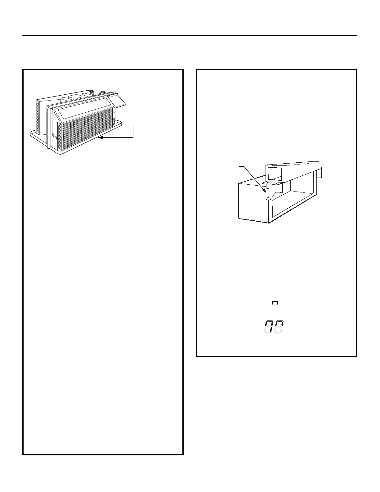
Instructions d’installation
REMISE EN PLACE D’UN APPAREIL EXISTANT?
Remise en place d’un appareil canalisé
érifiez les
V
renseignements
importants contenus
dans l’étiquette
« Éléments
essentiels ».
Nouvelle installation canalisée :
Si vous devez installer cet appareil dans uneinstallation
nouvelle canalisée utilisant une trousse d’adaptateur de
canalisation, vous devez installer la trousse avant de
placer l’appareil dans le boîtier mural. Les instructions
d’installation sont contenues dans la trousse.
Trousse d’adaptateur de canalisations :
RAK6052
RAK601/602
Utilisez le bon boîtier mural
Cet appareil est conçu pour être installé dans un
boîtier mural GE en matière plastique ou en métal
isolé. Cela minimise la formation de condensation
du côté de la chambre du boîtier.
Si le boîtier mural existant n’est pas isolé, vous pouvez
réduire la formation de condensation en installant la
trousse d’isolement RAK901L, que vous trouverez là où
vous avez acheté votre appareil.
NOTE : Il y a des trous supplémentaires sur les rebords
situés du côté de votre appareil, pour permettre son
installation dans des boîtiers muraux autres que le boîtier
GE. Pour éviter d’endommager l’isolement du rebord,
l’installateur doit utiliser un poinçon ou un autre outil
aiguisé pour trouer l’isolement dans les bons trous avant
de visser les vis de fixation.
Utilisez la bonne grille extérieure
Vous devez utiliser les grilles extérieures indiquées sur
l’étiquette « Éléments essentiels » sur le plateau.
• Si une grille existante n’est pas remise en place, la
capacité et l’efficience de l’appareil sont réduites et
l’appareil peut s’arrêter de bien fonctionner ou s’arrêter
complêtement de fonctionner. Vous pouvez utiliser une
trousse de déflecteur, RAK40, avec des grilles qui n’ont
pas été conçues pour votrenouveau Zoneline GE. La
trousse RAK40 contient des déflecteurs d’air et des joints
que vous pouvez monter sur votre appareil pour diriger
l’air chaud afin de le faire sortir loin de l’entrée d’air, de
manière à permettre à l’appareil de bien fonctionner.
La grille doit avoir une surface libre d’au moins 65 %.
• Vous devez enlever tout déflecteur vertical sur la grille
arrière existante pour diminuer la recirculation d’air
du condensateur qui peut faire arrêter et remettre
en marche l’appareil et peut occasionner une panne
prématurée des éléments.
Plaque de
montage
Installations canalisées existantes :
Le remplacement d’un appareil canalisé existant peut
nécessiter différents éléments. Demandez ces
renseignements à votre représentant des ventes.
• Remise en placed’appareils de 230/208 volts :
Voir à la page13.
• Remise en placed’appareils de 265 volts :
Voir aux pages 14.
Lorsque vous utilisez une trousse de canalisations, le Mode
7 doit toujours être activé « ». Veuillez vous référer aux
instructions sur les Modes en page 7.
Mode canalisé
representé activé
Canalisation
Boîtier
Utilisez le bon cordon d’alimentation
Les codes locaux peuvent exiger l’utilisation de
mécanismes de détection de fuites ou de panne d’arc
sur les installations de 230/208 volts.
12
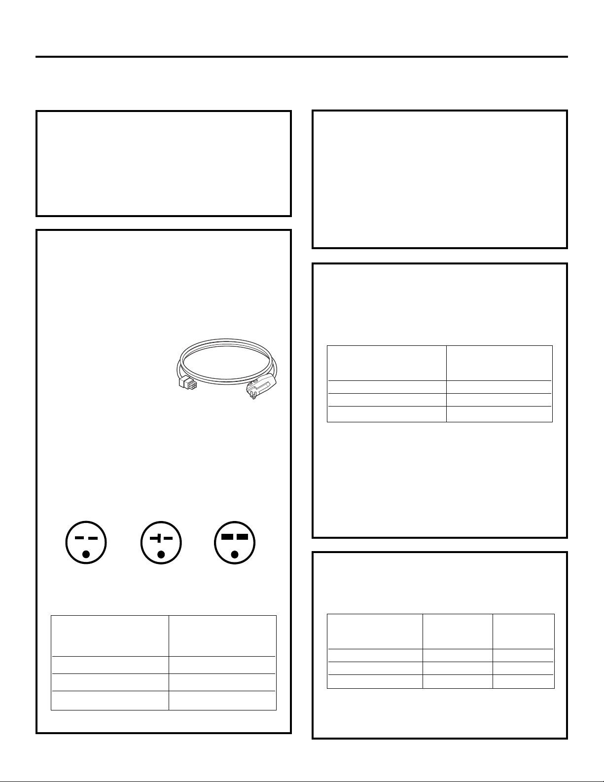
Instructions d’installation
OPTIONS DE BRANCHEMENT ÉLECTRIQUE DE 230/208 VOLTS
BRANCHEMENT
1 Enlevez la carrosserie côté chambre.
2 Branchez au courant électrique.
3 Consultez les étapes suivantes pour les tensions
d’alimentation.
4 Ré-installez la carrosserie côté chambre.
BRANCHEMENT DE CORDON
D’ALIMENTATION
Une trousse d’alimentation électrique avec LCDI doit être
utiliséepourl’alimentation électrique du Zoneline. La bonne
trousse dépend de la tension, le mécanisme de branchement
électrique et l’ampérage du
circuit de dérivation.
Le branchement à un circuit
de 208 ou de 230 volts peut
se faire avec une trousse
d’alimentation électrique ou
une trousse de boîte de
dérivation.
Vous devez faire tout le
câblage, y compris l’installation de la prise de courant,
conformément au CNE et aux ordonnances, réglements
et codes locaux. Les codes exiger l’utiliser d’un
mécanisme de détection de panne d’arc ou de courant
de fuite sur le cordon d’alimentation sauf en
raccordement direct. Assurez-vous de choisir le bon
cordon d’alimentation pour votre installation.
L’aspect peut varier.
Trousse d’alimentation électrique
Les cordons d’alimentation peuvent comprendre un
mécanisme d’interruption en cas de détection de
ourant de fuite ou d’interruption de panne d’arc. Un
c
bouton d’essai et de remise en marche est fourni sur le
boîtier de la prise ou sur le boîtier en ligne. Vous devez
essayer le mécanisme périodiquement en appuyant
d’abord sur le bouton TEST (essai) puis sur le bouton
RESET (remise en marche). Si le bouton TEST (essai) ne
bascule pas ou si le bouton RESET (remise en marche)
ne reste pas enfoncé, cessez d’utiliser votre Zoneline
et appelez un technicien de service qualifié.
BRANCHEMENT DE
SOUS-BASE ÉLECTRIQUE
Vous pouvez installer les modèles 230/208 volts en
utilisant l’une des sous-bases électriques suivantes :
Intensitéen ampères
du circuit dedérivation Bonne trousse
et del’appareil de sous-base GE
15 RAK204D15P
20 RAK204D20P
30 RAK204D30P*
*Non approuvé pour utilisationsur lesmodèles de 7000 BTU.
Les sous-bases électriques fournissent une enceinte
pour branchement direct ou des prises closes. Le cordon
d’alimentation est compris dans la trousse de sous-base.
Vous devez suivre soigneusement les instructions fournies avec
la trousse choisie de sous-base. L’installateur est responsable
d’assurer que les éléments soient branchés conformément
à ces instructions et à tous les codes électriques.
Tandem
15 amp.
Configuration de prise 230/208 volts.
Intensité en ampères Bon cordon
du circuit de dérivation d’alimentation GE
et de l’appareil avec mécanisme LCDI
*Non approuvé pour utilisation sur les modèles de 7000 BTU.
Perpendiculaire
20 amp.
15 RAK3153
20 RAK3203
30 RAK3303*
Grosse tandem
30 amp.
BRANCHEMENT DIRECT
Commandez la trousse suivante pour un branchement
direct 230/208 volts, au besoin :
Intensité en ampères Accessoire Trousse
du circuit de dérivation d’alimentation d’alimentation
et de l’appareil électrique électrique
15 RAK4002A RAK4157
20 RAK4002A RAK4207
30 RAK4002A RAK4307*
*Non approuvé pour utilisation sur les modèles de 7000 BTU.
Passez à la section « BRANCHEMENT ÉLECTRIQUE DE
L’APPAREIL ».
13

Instructions d’installation
OPTIONS DE BRANCHEMENT ÉLECTRIQUE DE 265 VOLTS
AVERTISSEMENT :
Vous DEVEZbrancher ce produit alimenté par courrant
alternatif de 265 volts au circuit de dérivation par
branchement direct conformément au Code national
d’électricité. Le Code n’autorise pas le branchement de
votre appareil à une prise exposée montée sur le bâtiment.
Vous devez installer ces modèles à l’aide de la bonne trousse
d’alimentation électrique GE pour l’ampérage du circuit de
dérivation et la puissance du chauffage à résistance
électrique désirée. Utilisez le Tableau de contact électrique,
page 16, pour déterminer la bonne trousse requise. Vous
devez utiliser l’une des méthodes suivantes d’installation
(A ou B).
A. INSTALLATION AVEC SOUS-BASE
Des trousses de sous-bases électriques sont disponibles pour
fournir une enceinte flexible pour branchement direct.
Intensité en ampères Trousse
du circuit de dérivation Bonne trousse d’alimentation
et de l’appareil de sous-base GE électrique
15 RAK204E15 RAK5172
20 RAK204E20 RAK5202
30 RAK204E30 RAK5302*
B. INSTALLATION AVEC BRANCHEMENT
DIRECT
Si vousn’utilisez pas une sous-base électrique, vous devez
brancher directement au câblage du circuit de dérivation
à l’intérieur de la boîte de dérivation fournie en suivant
les étapes suivantes.
Commandez la trousse suivante pour un branchement
direct 265 volts, au besoin :
Intensitéen ampères
du circuit de dérivation d’alimentation
et de l’appareil électrique
15 RAK5157
20 RAK5207
30 RAK5307*
*Non approuvé pour utilisation sur les modèles de 7000 BTU.
Allez à la section « BRANCHEMENT ÉLECTRIQUE DE
L’APPAREIL ».
NOTE : Commandez la trousse RAK4002CW pour
permettre un débranchement rapide à l’intérieur
de la boîte de dérivation.
Trousse
*Non approuvé pour utilisation sur les modèles de 7000 BTU.
Vous devez suivre soigneusement les instructions fournies
avec la trousse choisiede sous-base. L’installateur est
responsable de s’assurer que les éléments soient branchés
conformémentà ces instructions et à tous les codes
électriques.
14

Instructions d’installation
BRANCHEMENT ÉLECTRIQUE DE L’APPAREIL
1
ENLEVEZ LA BOÎTEDE DÉRIVATION
1 E
nlevez le couvercle de la boîte de dérivation en
enlevant les deux vis de devant.
2 E
nlevez la boîte de dérivation en enlevant les vis de
l’arrière situées en haut et en bas. Notez la manière
dont les taquets situés au bas à gauche de la boîte de
dérivation servent à tenir le côté en place. Cela vous
aidera à réinstaller la boîte.
Contact de l’appareil
Couvercle
de la boîte
de dérivation
2
BRANCHEZ LE CORDON
Branchez bien le connecteur, qui est fourni dans la
trousse de branchement direct, dans le connecteur
correspondant de l’appareil. Assurez-vous de bien
engager les taquets qui verrouillent les côtés.
Contact
NOTE : Commandez la trousse RAK4002CW pour
permettre un débranchement rapide à l’intérieur
de la boîte de dérivation.
Boîte de
dérivation
3
FIXEZ LA CANALISATION
1 Utilisez l’alvéole défonçable en bas de la boîte
de dérivation pour fixer la canalisation qui vient
du circuit de dérivation. Enlevez l’alvéole, fixez
la canalisation et amenez les fils dans la boîte de
dérivation. Laissez 6 po de fils libres à l’extrémité de
la canalisationpour pouvoirfaire les branchements.
Canalisation
2 Si vous devezutiliser un fusible ou un porte-fusible,
l’alvéole défonçable située en haut de la boîte sert
à fixer un porte-fusible Buss. Assurez-vous que le
fusible et le porte-fusible aient la même puissance
que le circuit de dérivation. Les fils de connexion
au fusable peuvent être soudés en place, ou fixés
à l’aide de contacts à sertir femelles (prise) de
1/4 po homologués UL. Suivezles normes locaux.
4
RÉ-INSTALLEZ LA BOÎTE
DE DÉRIVATION
• Ré-installez la boîte de dérivation en engageant les
taquets de gauche situés sur la façade droite en bas
de l’unité, en alignant les trous de vis en haut et en bas
et en faisant passer les deux vis et les vissant jusqu’à
ce qu’elles tiennent bien. Assurez-vous que tous les fils
de connexion soient à l’intérieur de la boîte et ne soient
pas coincés entre la boîte et l’appareil. Le fil de
connexion vert isolé en provenance de l’appareil DOIT
être connecté au fil de mise à la terre du circuit de
dérivation.
Faites tous les contacts de fils à l’aide des bons
contacts et techniques électriques U/L (noir à noir,
blanc à blanc et vert à vert).
15
5
RÉ-INSTALLEZ LE COUVERCLE DE LA
BOÎTE DE DÉRIVATION
1 Groupez tous les fils et les contacts dans la boîte de
dérivation. Assurez-vous qu’il n’y ait aucun contact
lâche ou de fils non isolés exposés.
2 Placez le couvercle de la boîtede dérivation en place.
Remettez en place les deux vis enlevées plus tôt et
serrez fort.

Instructions d’installation
TABLEAU DE CONTACT ÉLECTRIQUE
Branchements de cordon d’alimentation
Trousse
d’alimentation
électrique
230/208 volts
avec mécanisme
de détection Configuration Mécanisme de Puissance du chauffage
de courant de prise murale protection de circuit @ 230/208 Volts
RAK3153 Tandem Fusible délai/disjoncteur de 15 amp 2,55/2,09 KW
RAK3203 Perpendiculaire Fusible délai/disjoncteur de 20 amp 3,45/2,82 KW
RAK3303* Gros tandem Fusible délai/disjoncteur de 30 amp 5,00/4,10 KW
Branchements directs
Trousse
d’alimentation
électrique Mécanisme de Puissance du chauffage
230/208 volts protection de circuit
RAK4157 Fusible délai/disjoncteur de 15 amp 2,55 KW/2,09 KW
RAK4207 Fusible délai/disjoncteur de 20 amp 3,45 KW/2,82 KW
RAK4307* Fusible délai/disjoncteur de 30 amp 5,00 KW/4,10 KW
Trousse
d’alimentation
électrique Mécanisme de Puissance du chauffage
265 volts protection de circuit
RAK5157 Fusible délai/disjoncteur de 15 amp 2,55 KW
RAK5207 Fusible délai/disjoncteur de 20 amp 3,45 KW
RAK5307* Fusible délai/disjoncteur de 30 amp 5,00 KW
@ 230/208 Volts
@ 265 Volts
*Non approuvé pour utilisation sur les modèles de 7000 BTU.
16

Instructions d’installation
INSTALLATION DU ZONELINE
1
INSTALLATIONDUBOÎTIER MURAL ET
DELAGRILLE EXTÉRIEURE
Vous devez bien installer le boîtier mural RAB77A4 ou
la série RAB71A, conformément aux instructions
comprises dans le boîtier.
• Enlevez le renforten carton et le panneau protecteur
extérieur. Utilisez la fente dans le panneau extérieur
pour soutenir votre main et faites sortir en poussant.
Panneau
protecteur
Renfort
• Installez la grille extérieure à partir de la chambre en
suivant les instructions contenues dans la grille.
Fente
2
PRÉPARATION DE L’APPAREIL
• Enlevez avec soins le ruban d’expédition et les
blocs d’expédition en mousse de la carrosserie
côté chambre, le compresseur et de la porte
de ventilation. Il peut y avoir plusieurs blocs et
morceaux de ruban d’expédition à enlever.
Ruban d’expédition
(L’emplacement
peut être différent)
• Enlevez la carrosserie côté chambre en la tirant
en bas pour la libérer (1), puis soulevez pour quitter
le rail le long du haut de l’appareil (2).
Boîtier mural isolé
Cette unité est conçue pour être installée dans un boîtier
mural en matière plastique GE ou en acier isolé. Cela
minimise la formation de condensation du côté
chambre du boîtier.
Les boîtiers muraux de la série RAB71A sont isolées.
La trousse d’isolement RAK901L estdisponible pour
une utilisation avec le modèle RAB77A4 ou des boîtiers
muraux non isolés existants, le cas échéant.
NOTE : Pour l’isolement avec une sous-base ou un
adaptateur de canalisation, consultez les instructions
contenues dans ces trousses.
• Pour faire fonctionner la porte de ventilation, enlevez
les vis d’expédition du côté avant de la porte de
ventilation, le cas échéant.
Enlevez deux
vis d’expédition
(si son utilisation
est requise)
17
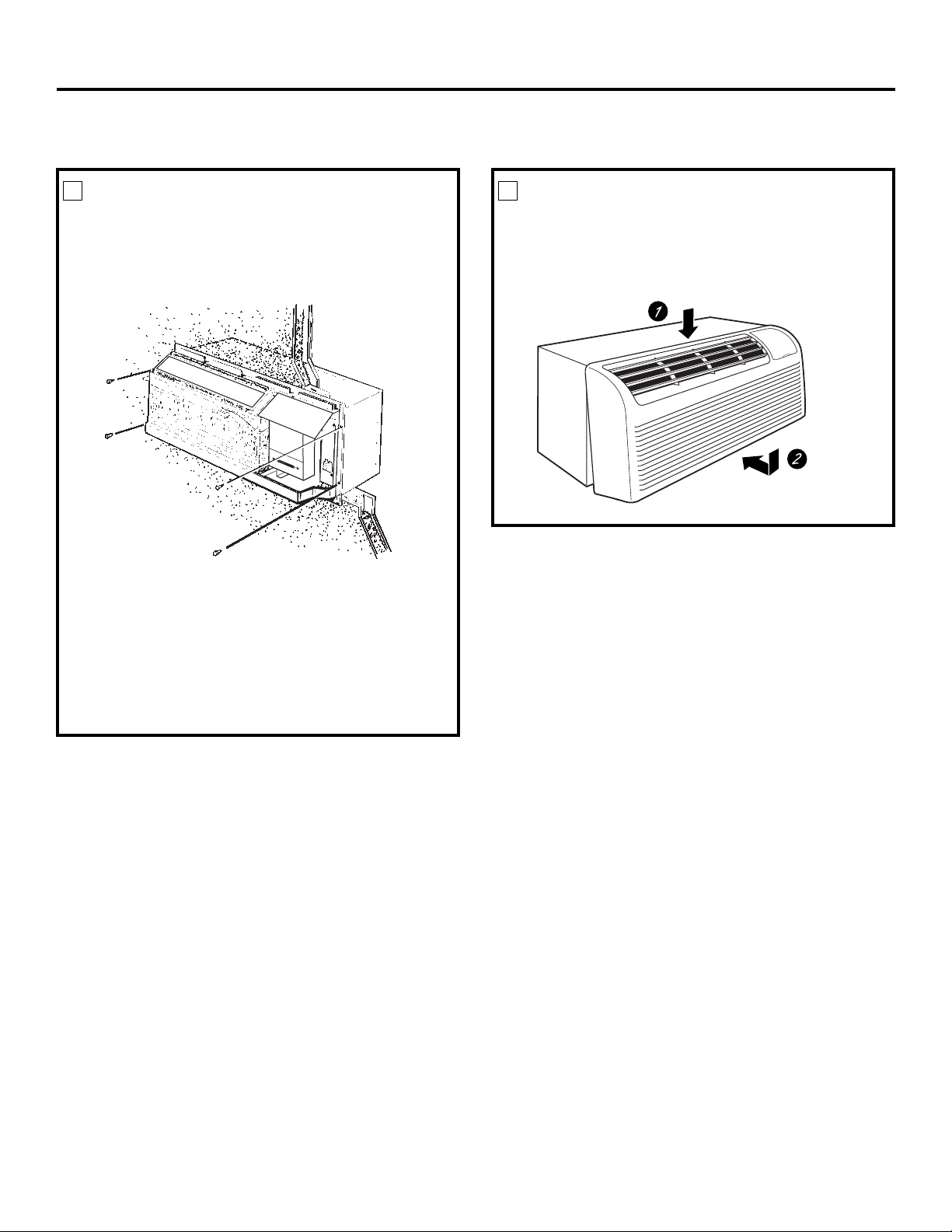
Instructions d’installation
INSTALLATION DU ZONELINE (suite)
3
INSTALLATION DE L’APPAREIL DANS
LE BOÎTIER MURAL
Faites glisser l’appareil dans le boîtier mural et fixez avec
quatre vis en les faisant passer par les trous de la bride
de l’appareil.
NOTE : Il y a des trous supplémentaires sur les rebords
situés du côté de votre appareil, pour permettre son
installation dans des boîtiers muraux autres que le
boîtier GE. Pour éviter d’endommager l’isolement du
rebord, l’installateur doit utiliser un poinçon ou un autre
outil aiguisé pour trouer l’isolement dans les bons trous
avant de visser les vis de fixation.
4
REMISE EN PLACE DU BOÎTIER
CÔTÉ CHAMBRE
Ré-installez le boîtier côté chambre en accrochant
le haut sur le rail du haut de l’appareil (1) puis en
poussant le boîtier en bas (2).
18

Instructions d’installation
EN OPTION—INSTALLATION DE LA TROUSSE
DE DRAINAGE
Les modèles Dry Air Série 25 sont conçus pour améliorer la déshumidification de 25 %. Comme l’air perdra davantage
d’humidité, cela augmente la possibilité que de l’eau coule du boîtier mural, par rapport à un appareil normal. Pour
empêcher cette eau de couler à l’intérieur des murs extérieurs du bâtiment, nous vous recommandons d’utiliser une
trousse de drainage RAD10.
Drainage extérieur
Consultez les instructions d’installation
dans la trousse RAD10.
Tube alternatif en cuivre
de 6 po de long, et de
1/2 po de diamètre extérieur
Drainage intérieur
Consultez les instructions d’installation
dans la trousse RAD10.
Trous carrés
de drainage
Tuyau de drainage de 1/2 po
de diamètre extérieur
Joint éponge en néoprène
Plaque de montage en acier
Vis de type A pour boîtier en métal ou
Vis de type B pour les boîtiers moulés
(L’évacuation est située
sousla carrosserie)
Trous carrés
de drainage
Joint éponge en néoprene
Plaque de montage en acier
Vis de type A pour boîtier en métal ou
Vis de type B pour les boîtiers moulés
19

Avant d’appeler un réparateur…
Conseils de dépannage—Économisez du temps et de l’argent!
Consultez d’abord les tableaux qui suiventet vous pourrezpeutêtre éviter de faire appel à un réparateur.
Problème Causes possibles Correctifs
Le Zoneline ne se met L’appareil estdébranché. • Assurez-vous de bien pousser la fiche du Zoneline
pas en marche dans la prise.
Le cordon d’alimentation • Enlevez la carrosserie côté chambre et assurez-vous
n’est pas bien branché. que le connecteur jaune à l’extrémité du cordon
d’alimentation soit bien branché.
Le fusible a sauté/ • Vérifiez le fusible/la boîte à fusibles de la maison
le disjoncteur a basculé. et remplacez le fusible ou rebranchez le disjoncteur.
L’appareil attend que le • C’est normal. Le Zoneline se remettra en marche
protecteur de surcharge après la remise en marche du protecteur.
du compresseur se remette
en marche.
Panne de courant. • S’il se produit une pannede courant, réglez la commande
de mode en position STOP (arrêt). Quand le courant revient,
réglez la commande de mode dans la position désirée.
• Il y a un délai de protection (jusqu’à 3 minutes)
pour empêcher le déclanchement de la surcharge
de compresseur. Aussi, l’appareil peut ne commancer
à réchauffer ou à rafraîchir normalement qu’après
un délai de 3 minutes.
Le mécanisme d’interruption • Appuyez sur le bouton RESET (remise en marche) situé
de courant est déclanché. sur la fiche du cordon électrique ou sur le boîtier près
de la fiche.
• Sile bouton RESET(remiseen marche)ne reste pas
enfoncé, arrêtez le Zoneline et appelez un technicien
qualifié.
Le Zoneline ne L’entrée d’air de l’extérieur • Assurez-vous qu’il n’y ait pas de rideau, de tenture ou
rafraîchit pas ou ne est réduite. de meuble qui bloque l’avant du Zoneline.
réchauffe pas autant
qu’il devrait
Soutien au consommateur Conseils de dépannage Entretien et nettoyage Fonctionnement Mesures de sécurité
20
La circulation de l’air extérieur • Assurez-vous que la grille d’air ne soit pas bouchée.
est réduite ou l’air recircule. Cela peut faire arrêter l’appareil à cause du protecteur
de surcharge du compresseur.
• La grille extérieuredoit avoir au moins 65 % de surface
libre. Les grilles qui ne sont pas GE peuvent être trop
petites pour bien fonctionner. Consultez votre vendeur
pour obtenir de l’aide.
La commande de température • Réglez la commande à une température plus basse ou
peut ne pas avoirété bien réglée. plus élevée. NOTE : Leréducteur detempérature peut limiter
laportée de latempérature.
Le filtre d’airest sale. • Nettoyez le filtre au moins tous les 30 jours. Consultez
la section Fonctionnement.
La chambre peut avoir été • Quand vous mettez en marche pour la première fois
chaude ou froide. le Zoneline, vous devez donner à la chambre le temps
de se réchauffer ou de se rafraîchir.
De l’air de l’extérieur entre • Réglez la commande en position fermé.
dans la chambre.

ww.electromenagersge.ca
w
Problème Causes Possibles Correctifs
Odeur de brûlé au Il y a de la poussière sur • Cela peut occasionner une odeur de brûlé au début
début des operations l’élément de chauffage. des opérations de réchauffement. Cette odeur doit
de réchauffement disparaître rapidement.
L’air n’estpas toujours La pompe à chaleur ne produit • C’est normal. La pompe à chaleur produit de l’air chaud,
chaud ou froid pendant pasd’airchaud. mais pas aussi chaud que l’air produit quand la chaleur
le fonctionnement électrique à haut coût est utilisée.
Les commandes auxiliaires • Le ventilateur souffle de l’air à la température
du Ventilateur intelligent ambiante, même quand le compresseur ou le
peuvent être réglées sur chauffage s’arrête. Le mouvement d’air continu
Ventilation en Continu. fournit une meilleure commande de la température
en mode de refroidissement. Voir Ventilateur
intelligent—Refroidissement/Chauffage à la page 5.
L’air ne semble pas La pompe à chaleur produit • Utilisez l’option de réchauffement électrique. Cela
suffisamment chaud seule de l’air qui semble arrête la pompe à chaleur et réchauffe uniquement
pendant l’opération plus froid que désiré. avec le chauffage électrique. NOTE : L’utilisation de
de réchauffement cette option occasionne une augmentation de la
consommation d’énergie.
Mesures de sécurité Fonctionnement Entretien et nettoyage Conseils de dépannage Soutien au consommateur
L’appareil ne souffle Les commandes auxiliaires • Voir Ventilateur intelligent—Refroidissement/Chauffage
pas d’air du Ventilateur intelligent à la page 5.
peuvent être réglées sur
Ventilation par Intermittence.
La caractéristique Le cordon d’alimentation • Enlevez la carrosserie côté chambre et assurez-vous
de réchauffement n’est pas bien branché. que le connecteur jaune à l’extrémité du cordon
électrique ne d’alimentation soit bien branché.
fonctionne pas
L’afficheur de Le compresseur pourrait • Réglez la commande de fonctionnement à STOP puis
température clignote être défectueux. redémarrez l’appareil. Si le témoin clignotant réapparaît
dans les 30 minutes qui suivent, appelez un réparateur.
21
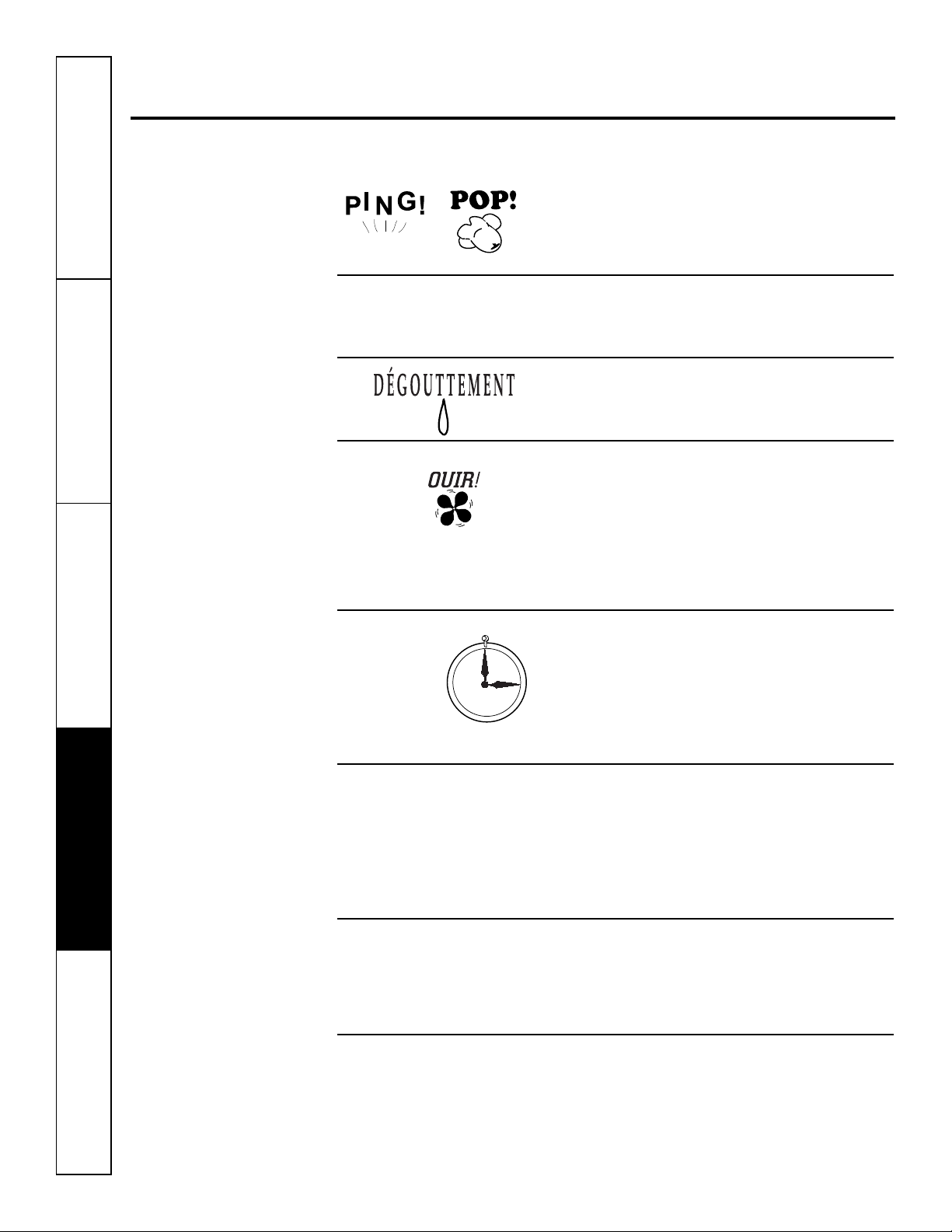
Ces bruits sont normaux.
Bruits normaux de fonctionnement
“CLIC”
Vous pouvez entendre un ping causé par de l’eau
qui est ramassée et envoyée contre le condensateur
un jour pluvieux ou très humide. Cette caractéristique
diminue l’humidité et améliore l’efficience de l’appareil.
Vous pouvez entendre lesrelais cliqueter quand les
commandes arrêtent et mettenten marche l’appareil,
ou s’ajustent pour changer la température ambiante.
De l’eau s’amasseradans le plateau lesjours pluvieux
oude grandehumidité. L’eaupeutdéborder et couler
du côté extérieur de l’appareil.
Le ventilateur intérieur fonctionnecontinuellement
quand l’appareil fonctionne en mode de
refroidissement, à moins que le commutateur de
ventilateur sous lacarrosserie côtéchambresoitréglé
en cycle ventilateur (UP, versle haut). Cela fait démarrer
et arrêter le ventilateur avecle compresseur. Vous
pouvez aussi entendreun bruit de ventilateurquand il
s’arrête et se met en marche.
Délai de
3 minutes
SILENCE
PROTECTION DU
COMPRESSEUR
Vous pouvez noter un délai de quelques minutes
quand vous essayez de remettre en marche votre
Zoneline trop tôt après l’avoir arrêté ou si vous ajustez
le thermostat juste après l’arrêt du compresseur. C’est
dû à un mécanisme intégré de protection du
compresseur en cas de remise en marche qui
occasionne un délai de 3 minutes.
Pendant le cyclede dégel, le ventilateur intérieur et
le ventilateur extérieur s’arrêtent et le compresseur
fonctionne en mode de rafraîchissement pour dégeler
le serpentin extérieur. Après ce dégel, l’appareil se
remet en marche en mode de chauffage électrique
pour réchauffer rapidement
la chambre à la température désirée.
Pour protéger le compresseur et éviter des arrêts et
des remises en marche répétés, l’appareil est conçu
pour fonctionner au moins 3 minutes après la mise
en marche du compresseur à n’importe quel réglage
de thermostat.
Soutien au consommateur Conseils de dépannage Entretien et nettoyage Fonctionnement Mesures de sécurité
22
Garantie Zoneline. www.electromenagersge.ca
Mesures de sécurité Fonctionnement Entretien et nettoyage Conseils de dépannage Soutien au consommateur
Tout le service en vertu de la garantie est offert par nos centres
de service d’usine ou par un technicien autorisé de Customer
®
Care
. Pour obtenir le service, contactez Gordon Williams Corp.
au 1.888.209.0999. Veuillez fournir le numéro de série et le
Agrafez le reçu d’achat ici.
our obtenir le service sous
P
garantie, vous devrez fournir
la preuve de l’achat original.
numéro de modèle lorsque vous appelez pour obtenir le service.
Pour la période de : GE remplacera gratuitement :
Un an Toute pièce du Zoneline présentant un défaut dû au materiél ou à la main-d’oeuvre.
À compter de la date Au cours de cette garantie limitée d’un an, GE couvrira gratuitementles frais de main
d’achat original d’oeuvre et de service connexe pour le remplacement de la pièce défectueuse.
Cinq ans Toute pièce du système scellé de réfrigération (compresseur, condenseur, evaporateur et
À compter de la date tuyauterie) présentant un défaut dû au materiél ou à la main-d’oeuvre. Au cours de cette
d’achat original garantie limitée additionnelle de quatre ans, GE couvrira gratuitement les frais de main
d’oeuvreet de service connexe pour le remplacement de la pièce défectueuse.
Cinq ans De la deuxième à la cinquième année depuis la date d’achat original, GE remplacera certaines
À compter de la date pièces qui présentant un défaut dû au materiél ou à la main-d’oeuvre. Les pièces couvertes sont
d’achat original les moteurs de ventilateur, les commutateurs, les thermostats, le chauffage, les protecteurs
de chauffage, la surcharge de compresseur, les solénoïdes, les cartes de circuit imprimé, les
thermistances, les commandes de gel, la pompe ICR, les condensateurs, les variateurs et
le roulementà bille de la souffleuse intérieure. Pendant cette garantie limitée additionnelle
de quatre ans, vous serez de tous les frais de main-d’oeuvre et de service connexe.
Ce qui n’est pas couvert :
■ Toute visite à votre site pour vous expliquer le
fonctionnement de l’appareil.
■ Une installation, livraison ou entretien inadéquate.
■ Si vous avez un problème d’installation, ou si
l’appareil de conditionnement d’air ne rafraîchit pas
suffisamment à votre goût, appelez votre revendeur ou
votre installateur.Vous êtes responsable de fournir une
installation adéquatede branchement électrique.
■ Dans des locaux commerciaux, la main-d’oeuvre
nécessaire pour transporter l’appareil jusqu’à un
emplacement où il peut être réparé ou entretenu par
un technicien qualifié.
■ Toute panne ou tout dommage occasionné par la
corrosion due à l’installation ou à un milieu contenant
des produit chimiques corrosifs.
■ Le remplacement des fusibles ou le réenclenchement
desdisjoncteurs.
■ Toute panne de l’appareil résultant de modifications
à l’appareil ou occasionnée par une utilisation non
raisonnable, en particulier un manquement de fournir
un entretienraisonnable et nécessaire.
■ Toute panne ou dommage résultant d’une corrosion
due à une installation à proximité de la mer, sauf s’il
s’agit d’un modèle traité à l’usine contre la corrosion,
comme l’indique son numéro de modèle.
■ Tout dommage au produit attribuable à voltage
impropre d’alimentation électrique, un accident, un
incendie, une inondation ou un cas de force majeure.
■ Tout dommage direct ou indirect à la propriété
privée causé en raison d’une défectuosité
éventuelle de cet appareil.
■ Tout dommage subi après livraison.
■ Le service s’il est impossible d’avoir accès au produit
pour ce faire.
EXCLUSION DE GARANTIES IMPLICITES – Votre seul et unique recours est la réparation du produit selon les
dispositions de cette Garantie limitée. Toutes les garanties implicites, incluant les garanties de commercialité et
d’adéquation à un usage spécifique, sontlimitées à une année ou à la période la plus courte autorisée par la
législation.
Cette garantie couvre l’acheteur original et tout possesseur subséquent de produits achetés pour un usage
au Canada. Si le produit est installé dans une région où ne se trouve aucun réparateur autorisé GE, vous devrez
peut-être assumer les frais de transport ou apporter expédier le produit à un centre de service autorisé GE.
Certaines provinces ne permettent pas l’exclusion ou la limitation des dommages indirects ou consécutifs et, par
conséquent, l’exclusion ci-dessus peut ne pas s’appliquer à vous. Cette garantie vous donne des droits juridiques
particuliers et vous pouvez également avoir d’autres droits qui varient d’une province à l’autre. Pour connaître vos
droits juridiques dans votre province, consultez votre bureau local ou provincial de protection des consommateurs.
Garant : General Electric Company. Louisville, KY 40225
23

Soutien au consommateur.
Site Web appareils électroménagers GE
Vous avez une question ou vous avez besoin d’aide pourvotreappareil électroménager? Contactez-nouspar
nternet au site www.electromenagersge.ca 24 heures par jour, tous les jours de l’année.
I
www.electromenagersge.ca
Service de réparations 1.800.561.3344
Service de réparations GE est tout près de vous.
Pour faire réparer votre électroménager GE, il suffit de noustéléphoner.
Studio de conception réaliste
Sur demande, GEpeut fournir une brochure sur l’aménagement d’une cuisine pour les personnes
à mobilité réduite.
Écrivez: Directeur, Relations avec les consommateurs, Mabe Canada Inc.
Bureau 310, 1 Factory Lane
Moncton, N.B. E1C 9M3
Pièces et accessoires
Ceux qui désirent réparer eux-mêmes leurs électroménagers peuvent recevoir pièces et accessoires
directement à la maison (cartes VISA, MasterCard et Discover acceptées).
Les directivesstipulées dans le présent manuel peuvent être effectuées par n’importe quel utilisateur. Les
autres réparations doivent généralement être effectuées par un technicien qualifié. Soyez prudent, car
une réparation inadéquate peut affecter le fonctionnement sécuritairede l’appareil.
Vous trouverez dans les pages jaunes de votre annuaire le numéro du Centre de service Mabe le plus proche.
Autrement, appelez-nous au 1.800.661.1616.
Contactez-nous
Si vous n’êtes pas satisfait du service après-vente dont vous avez bénéficié :
Premièrement, communiquez avec les gens qui ont réparé votre appareil.
Ensuite, si vous n’êtes toujours pas satisfait envoyez tous les détails—numéro de téléphone compris—au
Directeur, Relations avec lesconsommateurs,Mabe Canada Inc.
Bureau 310, 1 Factory Lane
Moncton, N.B. E1C 9M3
Inscrivez votre appareil électroménager
Inscrivez votre appareil électroménager en direct, aussitôt que possible. Celaaméliorera nos
communications et notre service après-vente. Vous pouvez également nous envoyer par la poste
le formulaire d’inscription joint à votre documentation.
24

GEAppliances.com
®
Zoneline
Instrucciones de seguridad . . . . . . . . . . . .2
Instrucciones de operación
Cómo retirar el gabinete del ambiente . . . . . .4
Control de ventilación . . . . . . . . . . . . . . . . . . . .4
Controles . . . . . . . . . . . . . . . . . . . . . . . . . . . . . . . .3
Controles auxiliares . . . . . . . . . . . . . . . . . . . .5–8
Dirección del aire . . . . . . . . . . . . . . . . . . . . . . . .4
Cuidado y limpieza
Bandeja de la base . . . . . . . . . . . . . . . . . . . . . . .9
Filtro de ventilación . . . . . . . . . . . . . . . . . . . . . .9
Filtros de aire . . . . . . . . . . . . . . . . . . . . . . . . . . .10
Gabinete del ambiente y montante . . . . . . .9
Serpentinas externas . . . . . . . . . . . . . . . . . . . . .9
Instrucciones de instalación
Conexión eléctrica . . . . . . . . . . . . . . . . . .13–16
¿Desea cambiar una unidad
ya instalada? . . . . . . . . . . . . . . . . . . . . . . . . . . .12
Instalación del acondicionador
de aire Zoneline . . . . . . . . . . . . . . . . . . . . .17, 18
Kit de drenaje opcional . . . . . . . . . . . . . . . . . .19
Preparación . . . . . . . . . . . . . . . . . . . . . . . . . . . .11
Manual del propietario
e instrucciones
de instalación
Modelo de refrescar/
calentar 4100
Modelo de bomba
de calor 6100
Acondicionador de aire
Solucionar problemas . . . . . . . . . .20, 21
Sonidos normales de operación . . . . . . . . .22
Soporte al consumidor
Garantía . . . . . . . . . . . . . . . . . . . . . . . . . . . . . . . .23
Soporte al consumidor . . . . . . . . . . . . . . . . . . .24
Escriba los números de modelo
y serie aquí:
# de Modelo__________________
# de Serie____________________
Estos números se encuentran en una
etiqueta ubicada detrás del gabinete
del ambiente sobre la bandeja de
la base.
TINSEA576JBRZ 49-7612-1S 07-09 JR

INFORMACIÓN IMPORTANTE DE SEGURIDAD.
LEA TODAS LAS INSTRUCCIONES ANTES DE USAR.
¡ADVERTENCIA!
Por su seguridad, se debe seguir la información en este manual para minimizar el riesgo
de incendio o explosión, descargas eléctricas, o para evitar daños a la propiedad, lesiones
personales, o la muerte.
PRECAUCIONES DE SEGURIDAD
■ Antes de iniciar su uso, el acondicionador
de aire Zoneline debe instalarse
correctamente según las Instrucciones
de instalación. Ver las Instrucciones de
instalación en la parte trasera de este
manual.
■ Reemplace inmediatamente todos los
cables eléctricos que se hayan pelado
o que se hayan dañado de alguna otra
manera. Un cable de corriente dañado
no debe repararse, sino que debe ser
sustituido por uno nuevo que se adquiera
del fabricante. No use un cable eléctrico
que muestre evidencias de deterioro, o
daños de abrasión en su superficie en
alguno de sus extremos.
■ Desenchufe o desconecte el Zoneline
desde la caja de fusibles o el disyuntor
antes de realizar cualquier tipo de
reparación.
NOTA: Recomendamos enérgicamente que
cualquier servicio llevado a cabo en este
equipo lo realice un individuo calificado.
■ Los sistemas de acondicionador de aire
R410A requieren que los contratistas y
técnicos utilicen herramientas,
equipamiento y normas de seguridad
aprobadas para su uso con este
refrigerante. NO utilice equipamiento
certificado sólo para refrigerante R22.
¿Desea reemplazar una unidad ya
instalada?
Para más detalles, ver las Instrucciones
de instalación en este manual.
LEA Y SIGA ESTAS INSTRUCCIONES DESEGURIDAD
CUIDADOSAMENTE.
GUARDE ESTAS INSTRUCCIONES
Soporte al consumidor Solucionar problemas Cuidado y limpieza Operación Seguridad
2
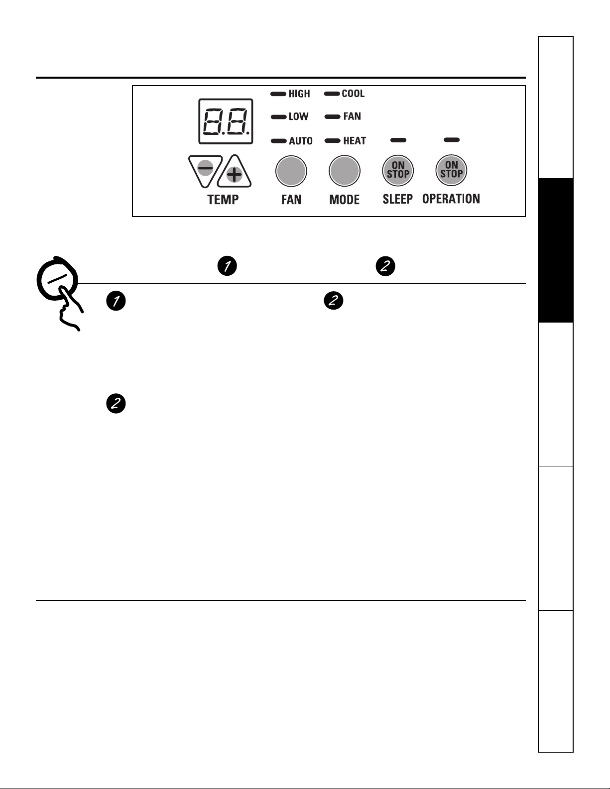
Sobre los controles del Zoneline. GEAppliances.com
Seguridad Operación Cuidado y limpieza Solucionar problemas Soporte al consumidor
CONTROL DE
TEMPERATURA
Controles
Control de temperatura
El control de temperatura se usa para mantener la
temperatura ambiente. El compresor se encenderá
y apagará para mantener la habitaciónal mismo
nivel de comodidad.
+
Pulse el botón para subir la temperatura.
Pulse el botón para bajar la temperatura.
NOTA: La pantalla muestra la temperaturaconfigurada,
no la temperatura ambiente.
Suspensión
Pulse para configurar el acondicionador de aire para
que funcione durante 8 horasantes de que vuelva
automáticamente a la configuración anterior.
Cuando esté en el modode enfriamiento y se active
el apagado automático, la temperatura establecida
aumentará automáticamente 2°F (–1,1°C) después de
la segunda hora y luego 1°F (–0,6°C) cada
hora durante las dos horas siguientes. Además,
la velocidad del ventilador cambiará a lenta. Cuando
esté en el modo de calefacción,la temperatura
establecida bajará de la misma manera.
Para cancelar el apagado automático, pulse el botón
MODE o el botón SLEEP otra vez.
▲
▼
–
OPERACIÓN DE VENTILADOR,
MODO Y SUSPENSIÓN
Control del ventilador, modo
y operación
FAN—Establece la operacióndel ventilador
a la velocidad ALTA (HIGH), BAJA (LOW) o
AUTOMÁTICA (AUTO). Cuandose pone en AUTO,
se cambia automáticamente entre LOW y HIGH
según cambie la temperatura ambiente.
MODO—COOL—Para enfriamiento
FAN—Parala operación del
ventilador únicamente
HEAT—Para calefacción
OPERATION—ON/STOP (ENCENDIDO/DETENER)—
Enciende o apaga launidad.La electricidad permanece
conectada al Zoneline. Las características de Freeze/
Heat Sentinel (monitor de congelamiento/calor) siguen
funcionandosi seencuentraactivo. Consulte lasección
deMonitor de congelación/Monitor de calor de la página 6.
NOTA: El visualizador de la temperatura mostrará
una luz intermitente para indicar una posible falla
de la unidad. Establezca el control de operación
en STOP (detener) y luego encienda de nuevo la
unidad. Si la luz intermitente aparece de nuevo en
menos de 30 minutos, llame para solicitar servicio.
Recuperación rápida de calor
Seactiva cadavez quesecambia eltermostato del modo STOP
(apagado) o COOL(frío)almodo HEAT(calor).Los calefactores
eléctricos se activan hastaquesehaya alcanzado elpunto definido
del termostato. Enlos modelos conbombadecalor,la operaciónde
esta bomba continuará en la siguienteactivacióndecalor.
Sobre la bomba de calor (Sólo serie 6100)
Se puede ahorrar dinero mediante el uso de las bombas
de calor, ya que toman el calor del aire exterior—incluso
cuando la temperatura externa se encuentra por debajo del
punto de congelación—y lo liberan dentro de la habitación.
A fin de obtener el mejor desempeño de su bomba
de calor, no modifique el termostato ambiental muy
a menudo. Si eleva la configuración de calor en 2–3 grados,
el Zoneline comenzará a utilizar sus elementos eléctricos de
calentamiento para alcanzar rápidamente la nueva
configuración de temperatura.
Para prevenir un encendido y apagado inmediato,
el compresorse toma un mínimo de tresminutos
para cambiar a cualquier configuración.
El motor de ventilación interna comienza a funcionarantes
que el compresor y se detiene después de que éste último
se hayaapagado.
Cuando la temperatura exterior es inferior a 25°F (–3,8°C),
el aire acondicionadorecibe el calor del calentadoreléctrico
en vez de hacerlo desde la bombade calor.
Los elementos eléctricos de calentamiento utilizan
mucha más electricidad que las bombas de calor,
y su operación resulta más costosa.
3

Otras características del Zoneline.
Control de ventilación
NOTA: Antes de comenzar a utilizar el aparato,
deben retirarse dos tornillos de empaque de la
uerta de ventilación. Ver las Instrucciones de
p
instalación en la parte trasera del manual. Si usted
no planea utilizar la característica de ventilación,
deje estos dos tornillos en su lugar.
La palanca de control de ventilación se encuentra
sobre el ladoizquierdo medio de la unidad
Zoneline, detrás del gabinete del ambiente.
Cuando se loconfigura enposición cerrada, sólo
circula y se filtra el aire dentro de lahabitación.
Cuando se lo configura en posición abierta,
se permite el ingreso de aireexterno a la
habitación. Esto reducirá la eficiencia para calentar
o enfriar el ambiente.
Consejo de ahorro de energía: Mantenga el
dispositivo de control en la posición cerrada. De ese
modo, el aire dentro del ambiente circulará y podrá
filtrarse.
Cómo retirar el gabinete del ambiente
Existen controles adicionales ubicados detrás
del gabinete del ambiente.
Para retirar: Jale de la parte inferior para
desengancharlo de las pestañas (1). Luego
empújelo hacia arriba (2).
osición
P
abierta
Control de
ventilación
(ubicado en la
posición media)
Posición
errada
c
Quite los tornillos
de embalaje
(si se desea
la operación)
Para volver a colocar: Coloque las pestañas sobre
el riel superior (1). Presione hacia adentro desde la
parte inferior hasta que encaje en su lugar (2).
Dirección del aire
Para cambiar la dirección del aire, retire el gabinete
del ambiente. Quite los 7 tornillos que sostienen la
rejilla de ventilación en su lugar. Gire la rejilla en
180°, vuelva a colocar los tornillos y el gabinete.
Tornillos de la rejilla
Soporte al consumidor Solucionar problemas Cuidado y limpieza Operación Seguridad
4
Tornillos de la rejilla
Para cambiar la dirección del aire, retire el gabinete
del ambiente y gire la rejilla en 180°.
Posición
predeterminada

Controles auxiliares del Zoneline. GEAppliances.com
Controles auxiliares—Botón de configuraciones auxiliares
Los controles de configuraciones auxiliares se
encuentran detrás del gabinete del ambiente,
debajo del panelde control.
Retire el gabinete del ambiente. Verla sección
Cómo retirar el gabinete del ambiente.
El propietario es responsable de garantizar que
los controles auxiliares se encuentren configurados
en la función deseada. Hay 9 modos diferentes
que puedenconfigurarse utilizando el botón
de configuraciones auxiliares. Para cambiar
los modos,presione AUX SET (aparecerá “AU”
en la pantalla). Presione el botón de modo sobre
la almohadilla de controluna determinada cantidad
de veces(indicada en el primer dígito de la pantalla) y
siga conla flecha ascendente o descendente (indicada
en el segundo dígito de la pantalla) para realizar una
selección.Presione el botónAUX SETpara confirmar
la selección.
Botón de configuraciones auxiliares
Tapa de acceso
Seguridad Operación Cuidado y limpieza Solucionar problemas Soporte al consumidor
MODE 1
MODE 2
Ventilador inteligente—Refrigeración/Calefacción
La configuración predeterminada para el Modo 1
es la siguiente:
Refrigeración: Continua (ON) (encendido)
Calefacción: Ciclo (OFF) (apagado)
Presione MODE (modo)hasta que aparezca un 1 en el
primer dígitode la pantalla para el modo de refrigeración
Smart Fan (ventilador inteligente). La luz LEDCOOL (frío)
delcontrol principal estaráencendida. Para cambiar al
modo de calefacción, presione MODE de nuevo. La luz
LEDHEAT (calor) del control principal estará encendida.
Presione la flecha descendentepara configurar el
encendido y apagado delventilador interno cuando
la unidad se encuentre calentando o enfriando " ".
Presione la flecha ascendente para configurarque el
ventiladorinterior funcione continuamente" ". Esto
puede verse en el segundo dígito de la pantalla. Presione
AUX SET (configuraciones auxiliares) para confirmar su
selección y salir delmodo AUX SET, o presione MODE
para continuar conla configuración de otrasfunciones.
Refrigeración – Ciclo
Refrigeración – Continua
Calefacción – Ciclo
Calefacción – Continua
Desconexión de carga (Control central)
La configuración predeterminadapara el Modo 2
es OFF(apagado).
Esta característica está activasólo si la unidad seencuentra
enel modo CDC. PresioneMODE(modo)hasta que
aparezcaun 2 en elprimerdígitodela pantallapara el
modo Load Shedding(desconexiónde carga). Presione
laflechadescendente para OFF(apagado)" " o laflecha
ascendente para ON(encendido) " ". Esto puedeverse
enel segundo dígito de lapantalla.Cuandoestemodo
está activado, el ventilador interiorpuede encenderse (ON)
o apagarse(OFF) medianteloscontroles dela unidad.
Cuando este modo está apagado,elbotón del ventilador se
encuentra desactivado. PresionAUX SET (configuraciones
auxiliares)para confirmarsu selección y salir del modo
AUX SET, o presione MODE (modo)para continuarcon
laconfiguración de otrasfunciones. La configuración
predeterminadapara el Modo 2 esOFF (apagado).
Desconexión de
carga apagada
(OFF)
HIGH (alta) COOL (frío)
LOW (baja) FAN (ventilador)
AUTO (automático) HEAT (calor)
HIGH (alta) COOL (frío)
LOW (baja) FAN (ventilador)
AUTO (automático) HEAT (calor)
HIGH (alta) COOL (frío)
LOW (baja) FAN (ventilador)
AUTO (automático) HEAT (calor)
HIGH (alta) COOL (frío)
LOW (baja) FAN (ventilador)
AUTO (automático) HEAT (calor)
Desconexión de
carga encendida
(ON)
5

Controles auxiliares del Zoneline.
MODE 3
MODE 4
Monitor de congelación/Monitor de calor
En la configuración predeterminada para el Modo 3, Heat Sentinel (monitor de
alor) se encuentra desactivado pero Freeze Sentinel (monitor de congelación)
c
se encuentra activado.
Presione MODE (modo) hasta que aparezca un 3 en el primer dígito de la pantalla
para el modo Freeze Sentinel (monitor de congelación). La luz LED COOL (frío)
del control principal estaráencendida. Presione MODE de nuevo paracambiar
a Heat Sentinel (monitor de calor). La luz LED HEAT (calor) del control principal
stará encendida. Presione la flecha descendente para OFF (apagado) " " o
e
la flecha ascendente paraON (encendido) " ". Esto puede verse en el segundo
dígito de la pantalla. Presione AUX SET (configuraciones auxiliares) para confirmar
su selección y salir del modo AUX SET, o presione MODE (modo) para continuar
con la configuración de otras funciones.
Cuando se activa Freeze Sentinel (monitor de congelación), se libera calor
automáticamente sin una interfaz de usuario. Esto ayuda a evitar daños en
las cañerías al encender (ON) la calefacción y el ventilador interior a 41ºFy
al apagarla (OFF) a 46ºF.
Cuandose activa Heat Sentinel (monitor de calor), se liberafrío automáticamentesin
una interfaz de usuario. Estoayuda a evitar unacalefacción excesiva alencender
(ON) el acondicionador de aire a 85ºF (30°C) y apagarlo (OFF) a 80ºF (27°C).
NOTA: Estas funciones se activan cuando la unidadse enchufa, aún si se
encuentra en la posición STOP (parar).
Ventilador encendido constante
La configuración predeterminada para el Modo 4 es OFF(apagado).
Presione MODE (modo)hasta que aparezca 4 en el primer dígito de la pantalla
para configurar el ventilador en funcionamiento continuo a altavelocidad, aún si
la unidad se encuentra en la posición STOP (parar). Presione la flecha descendente
para OFF(apagado) " " o la flecha ascendente para ON (encendido) " ."
Esto puede verse en el segundo dígito de la pantalla. Presione AUX SET
(configuraciones auxiliares) para confirmar su selección y salir delmodoAUX SET ,
o presioneMODE (modo) para continuar con la configuración de otras funciones.
HIGH (alta) COOL (frío)
LOW (baja) FAN (ventilador)
AUTO (automático) HEAT (calor)
Monitor de congelación apagado (OFF)
HIGH (alta) COOL (frío)
LOW (baja) FAN (ventilador)
AUTO (automático) HEAT (calor)
Monitor de congelación encendido (ON)
HIGH (alta) COOL (frío)
LOW (baja) FAN (ventilador)
AUTO (automático) HEAT (calor)
Monitor de calor apagado (OFF)
HIGH (alta) COOL (frío)
LOW (baja) FAN (ventilador)
AUTO (automático) HEAT (calor)
Monitor de calor encendido (ON)
Ventilador
constante
apagado (OFF)
Ventilador
constante
encendido (ON)
MODE 5
MODE 6
Soporte al consumidor Solucionar problemas Cuidado y limpieza Operación Seguridad
6
Limitación de temperatura
La configuración predeterminada parael Modo 5 es la siguiente:
Frío: 0 (60ºF [15°C] a 85ºF [30°C])
Calor: 7 (60ºF[15°C] a 85ºF [30°C])
Presione MODE (modo) hasta que aparezca un 5 en el primer dígito de la pantalla
para el modo de refrigeración Temperature Limiting (limitación de temperatura).
La luz LED COOL (frío)del control principal estará encendida. Para cambiar al
modo calor, presione MODE (modo) de nuevo y se encenderá la luz LED HEAT
(calor) del control principal.Para configurar los límites de temperatura, presione
las flechas ascendentes o descendentes. El segundo dígito de la pantalla se
hallará entre 0 y 7 dependiendo del límite que desea configurar. La tabla señala
los límites disponibles. Presione AUX SET (configuraciones auxiliares) para
confirmar su selección y salir delmodo AUX SET, o presione MODE (modo)
para continuar con la configuración de otras funciones.
Límites de temperatura – Frío Límites de temperatura – Calor
0 = 60°F a 85°F (15°C a 30°C) 0 = 60°F a 65°F (15°C a 18°C)
1 = 64°F a 85°F (18°C a 30°C) 1 = 60°F a 70°F (15°C a 21°C)
2 = 66°F a 85°F (19°C a 30°C) 2 = 60°F a 72°F (15°C a 22°C)
3 = 68°F a 85°F (20°C a 30°C) 3 = 60°F a 74°F (15°C a 23°C)
4 = 70°F a 85°F (21°C a 30°C) 4 = 60°F a 76°F (15°C a 24°C)
5 = 72°F a 85°F (22°C a 30°C) 5 = 60°F a 78°F (15°C a 26°C)
6 = 74°F a 85°F (23°C a 30°C) 6 = 60°F a 80°F (15°C a 27°C)
7 = 76°F a 85°F (24°C a 30°C) 7 = 60°F a 85°F (15°C a 30°C)
Termostato remoto—Clase 2
La configuración predeterminada parael Modo 6 es OFF (apagado).
Al configurar este modo en ON (encendido), la unidad puede funcionar con
un termostato de pared a control remoto de Clase 2. Presione MODE (modo)
hasta que aparezca un 6 en el primer dígito de la pantalla para el modo Class 2
(clase 2). Presione la flecha descendente para apagar (OFF) la opción " ."
Presione la flecha ascendente para encender (ON)la opción " ". Esto puede
verse en el segundo dígito de la pantalla. Presione AUX SET (configuraciones
auxiliares) para confirmar su seleccióny salir del modo AUX SET, o presione
MODE (modo) para continuar con la configuración de otras funciones.
HIGH (alta) COOL (frío)
LOW (baja) FAN (ventilador)
AUTO (automático) HEAT (calor)
Limitación de temperatura Frío – Límite 2
HIGH (alta) COOL (frío)
LOW (baja) FAN (ventilador)
AUTO (automático) HEAT (calor)
Limitación de temperatura Calor – Límite 3
Clase 2
apagado (OFF)
Clase 2
encendido (ON)

GEAppliances.com
n
Common
White - Heater
Yellow - Compressor
Black - Solenoid (AZ61 only)
Green - High Speed Fan
Green - Low Speed Fan
Red - 24 V AC only
EXT
FAN
CDC
24 VAC R
FAN LO G
FAN HI G
REV VAL B
COMP Y
AUX HEAT W
COMMON C
Seguridad Operación Cuidado y limpieza Solucionar problemas Soporte al consumidor
MODE 7
MODE 8
MODE 9
Modo para conductos
La configuración predeterminada para el Modo 7 es OFF (apagado).
Esta configuración se utiliza cuando la unidad se instala utilizando
n kit de adaptador de conductos. Si la unidad está instalada con
u
conductos, el Modo para conductos (Duct Mode) debe configurarse
en encendido (ON). Esto aumenta la velocidad del ventilador para
garantizar una circulación adecuada.
Presione MODE (modo) hasta que un 7 aparezca en el primer dígito
de la pantalla. Presione las flechas ascendente o descendente para
onfigurar este interruptor en apagado (OFF) " " o en encendido
c
(ON) " ". Esto puede verse en el segundo dígito de la pantalla.
Presione AUX SET (configuraciones auxiliares) para confirmar su
selección y salir del modo AUX SET.
Calor todo eléctrico (sólo AZ6100)
La configuración predeterminada para el Modo 8 es OFF (apagado).
Esta opción de calor eléctrico sólo funciona en el modelo 6100.
Cuando esta opción se encuentra activada (ON) " ", se anula el
funcionamiento con bomba de calor, por lo que la unidad sólo ofrece
calor por resistencia eléctrica.
Para configurar la opción All-Electric Heat (calor todo eléctrico),
presione MODE(modo) hasta que aparezca un 8 en el primer dígito
de la pantalla. Presione lasflechasascendente o descendente para
configurar este interruptor en apagado (OFF)" " o en encendido (ON)
" ". Esto puede verse en el segundo dígito de la pantalla.
Impulso de calor (sólo AZ6100)
La configuración predeterminada para el Modo 9 es OFF (apagado).
Cuando Heat Boost (impulso de calor) se encuentra activado (ON) y
las temperaturas externas se encuentran entre 25ºF y 46ºF, se anula
el funcionamiento de sólo bomba de calor. Esta configuración se
utiliza para ofrecer calor complementario al funcionamiento de
bomba de calor mediante calor por resistencia eléctrica en
condiciones en las que el funcionamiento de sólo bomba de calor no
es suficiente para mantener una temperatura ambiente congruente
y confortable. NOTA: La opción de Impulso de calor no debe utilizarse
con el funcionamiento de termostato remoto. Esto provocará que la
unidad cambie a calor por resistencia cuando la temperatura exterior
sea de 46ºF.
Para el Modelo AZ6100, presione MODE (modo) para continuar con
la configuración de otras funciones. Al presionar MODE en el Modelo
AZ4100, se volverá al modo AUX SET y “AU” aparecerá en la pantalla.
Modo para
conductos
apagado (OFF)
Modo para
conductos
encendido (ON)
Presione AUX SET (configuraciones auxiliares) para confirmar su
selección y salir del modo AUX SET, o presione MODE para continuar
con la configuración de otras funciones.
Calor todo
eléctrico
apagado (OFF)
Calor todo
eléctrico
encendido (ON)
Para configurar Impulso de calor, presione MODE (modo) hasta que
aparezca un 9 en el primer dígito de la pantalla. Presione las flechas
ascendente o descendente para configurar este interruptor en
apagado (OFF) " " o en encendido (ON) " ". Esto puede verse en
el segundo dígito de la pantalla. Presione AUX SET (configuraciones
auxiliares) para confirmar su selección y salir del modo AUX SET.
Impulso de calor
apagado (OFF)
Impulso de calor
encendido (ON)
Controles auxiliares—Conexiones terminales
Los controles auxiliaresestán ubicados detrásdel gabinete
del ambiente por debajo de la tapade acceso.
Apague y desenchufela unidad.
1
Retire el gabinete del ambiente. Ver la sección Cómo retirar
2
el gabinete del ambiente.
Quite el tornillo de la tapade acceso.
3
Para hacer conexiones eléctricas, insertelos cables en la parte
4
inferior de las terminales y ajuste bienlos tornillos.
Después de realizar todas las conexiones deseadas, vuelva
5
a colocar la tapa de acceso y el gabinete del ambiente.
Tapa de
acceso
Ventilador externo
Control de escritorio central
El propietario es responsable de realizar todas lasconexiones y
configurar el modo apropiado de AUX SET (configuraciones auxiliares).
PRECAUCIÓN:
Una conexión eléctrica incorrecta puede dañar las partes electrónicas
de su Zoneline. No se permite la conexión simultánea de varias
unidades en un mismo cable. Esto puede provocar daños o generar
un funcionamiento errático. Debe utilizarse un cable diferente desde
cada interruptor de control hacia cada Zoneline.
EXT
CEC
24 VAC R
VENTILADOR
VENTILADOR BAJO G
COMP Y
VAL REV B
VENTILADOR ALTO G
COMÚN C
CALOR AUX W
Común
Blanco – Calentador
Amarillo – Compresor
Negro– Solenoide(sóloAZ61)
Verde – Ventilador velocidad alta
Verde – Ventilador velocidad baja
Rojo – Sólo 24 V AC
7

Controles auxiliares del Zoneline.
Ventilador externo (disponible en forma local)
Una vez que se lo conecta, un ventilador auxiliar
o externo puede controlarse con el motor de ventilación
interno de Zoneline. Las conexiones brindan 24 voltios
de CA para suministrar energía a un circuito intermedio,
lo que enciende el ventilador externo.
Control central
Una vez que se la conecta, la unidad puede encenderse
o apagarse mediante una tecla ubicada en el panel
central de control. Debe utilizarse un cable diferente
desde cada interruptor de control hacia cada
acondicionador de aire Zoneline.
Para opciones de configuración de ventilador, consulte el
MODO 2 en la página 5.
Termostato remoto
Cuando se conecta a un termostato remoto, el sensor de
temperatura interior cambia de la unidad al termostato
remoto. Por esta razón, las unidades funcionarán con
ciertas diferencias cuando se conectan a un termostato
remoto. La siguiente tabla indica el funcionamiento de
la unidad cuando se conecta a un termostato remoto.
NOTA : La configuración de Modo Clase 2 (Modo 6) debe
configurarse en encendido (ON) " " para que la unidad
funcione con un termostato de pared remoto Clase 2.
(Ver las instrucciones de instalación incluidas con las
instrucciones del termostato remoto y de Modo de la
página 7).
EXT
Ventilador externo
EXT
Control de escritorio central
Verde – Ventilador velocidad baja
Verde – Ventilador velocidad alta
CEC
VENTILADOR
CEC
VENTILADOR
EXT
VENTILADOR
Rojo – sólo 24 V AC
Negro– Solenoide
Amarillo – Compresor
Blanco – Calentador
Común
24 VAC R
VENTILADOR BAJO G
24 VAC R
VENTILADOR BAJO G
CEC
24 VAC R
COMP Y
VAL REV B
VENTILADOR ALTO G
COMP Y
VAL REV B
VENTILADOR ALTO G
VENTILADOR ALTO G
VENTILADOR BAJO G
COMÚN C
CALOR AUX W
COMÚN C
CALOR AUX W
COMP Y
VAL REV B
COMÚN C
CALOR AUX W
Se muestra
encendido (ON)
PRECAUCIÓN:
Unas conexiones inadecuadas pueden provocar daños
al termostato de paredo a las partes electrónicas de
IMPORTANTE: Las conexiones del
termostato de Zoneline proveen sólo 24 voltios de CA.
Si utiliza un termostato de pared digital/electrónico,
éste debe configurarse a 24 voltios de CA. Ver las
Zoneline. Debe prestarse especial cuidado durante la
conexión de los cables. No deben realizarse conexiones
de línea con ningún circuito. Todos los cables del edificio
deben aislarse de la línea de tensión.
Instrucciones de instalación para el termostato de pared.
Característica Bomba de calor Calor eléctrico
Control de escarcha interno Sí Sí
Monitor de congelación Sí Sí
Velocidad de ventilador automática No No
Limitación de temperatura electrónica No No
Cambio a calor por resistencia en Determinado por N/A
base a la temperatura interior el termostato remoto
Cambio a calor por resistencia en Sí N/A
base a la temperatura exterior
Descongelación de ciclo inverso Sí N/A
Calor por resistencia simultáneo No N/A
con bomba de calor
Bloqueo de calor por resistencia Sí N/A
Ciclo de ventilador “Smart Fan” Ventilador configurado en ON/AUTO Ventilador configurado en ON/AUTO
Soporte al consumidor Solucionar problemas Cuidado y limpieza Operación Seguridad
(ventilador inteligente) (encendido/automático) (encendido/automático)
8
Control de escritorio central Sí Sí
en termostato remoto en termostato remoto
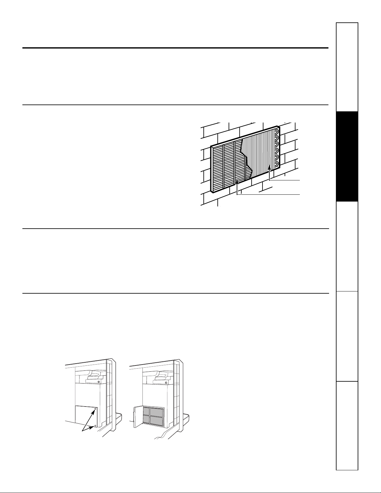
Cuidado y limpieza. G
Gabinete del ambiente y montante
EAppliances.com
Seguridad Operación Cuidado y limpieza Solucionar problemas Soporte al consumidor
Apague el Zoneline y desconecte el suministro
de energía.
Serpentinas externas
Las serpentinas de la zona externa del Zoneline
deben verificarse de manera regular. Si están
tapadas con suciedad u hollín, un experto puede
limpiarlas con vapor. Usted tendrá que quitar la
unidad de la funda de la pared para inspeccionar
las serpentinas. La suciedad se acumula en el lado
del ventilador de la serpentina exterior.
Bandeja de la base
En algunas instalaciones, suciedad y otros residuos
pueden ingresar a la unidad desde el exterior y
acumularse en la bandeja de la base (la parte
inferior de la unidad).
Para limpiarlo, use agua conun detergente suave.
No utilice blanqueador o sustancias abrasivas.
Algunos limpiadores comercialespueden dañar
laspartes plásticas.
Serpentinas
Parrilla
Limpie las serpentinas externas regularmente.
En algunas regiones de los EE.UU., puede verse una
sustancia “gelatinosa” o “babosa” de origen natural
en la bandeja de la base.
Realice unainspección periódica de la misma y
límpiela, si así fuese necesario.
Filtro de ventilación
Si la puerta de la ventilación está abierta, hay que
quitar la unidad de la funda de la pared para poder
acceder. Limpie el filtro de ventilación dos veces al
año o según sea necesario.
Apague el Zoneline y desenchúfelo antes de limpiar.
Quite los tornillos
de embalaje
(si se desea
la operación)
Para limpiar el filtro de ventilación:
IMPORTANTE:
Este filtro no es desmontable. Si trata de quitar
el filtro, dañará la unidad.
■ Use una aspiradora para limpiar el filtro.
■ Utilice un paño húmedo para limpiar el filtro
y el área circundante después de pasar
la aspiradora.
9
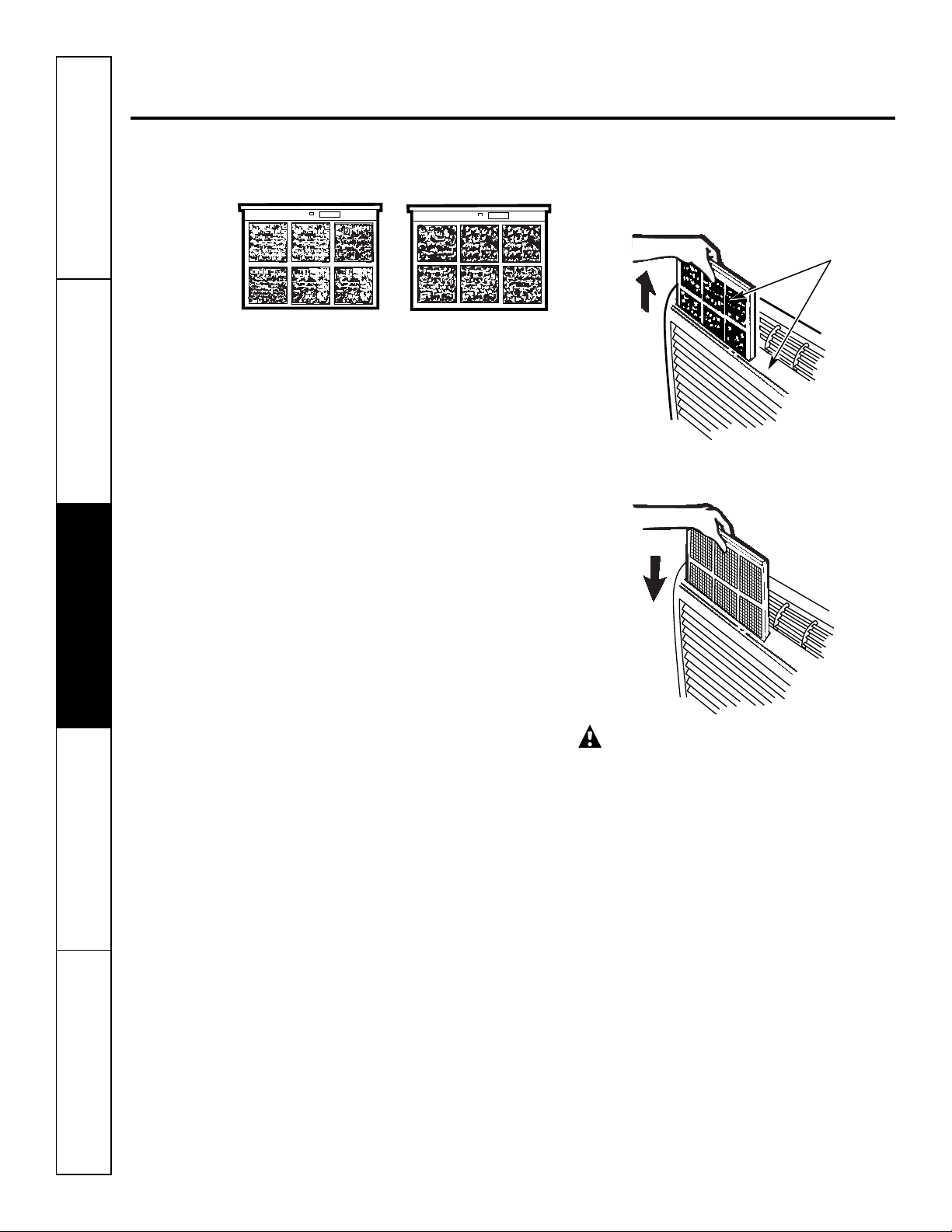
Cuidado y limpieza.
F
RONT
FRONT
Para mantener un funcionamiento óptimo, limpie los filtros cada 30 días.
Filtros de aire
Cómo retirar los filtros de aire:
Jale hacia
Filtro sucio—debe limpiarse Filtro obstruido—
Apague el Zoneline antes de limpiarlo.
Lo más importante que puede hacer para
mantener en buen estado su Zoneline es limpiar
el filtro por lo menos cada 30 días. Los filtros
obstruidos reducen la refrigeración, la calefacción
y la circulación de aire.
reduce en gran
medida la refrigeración,
la calefacción y
la circulación de aire.
Cómo volver a colocar los filtros de aire:
2 filtros de aire
arriba
Si mantiene los filtros limpios:
■ Reducirá el costo de la operación.
■ Ahorrará energía.
■ Prevendrá la obstrucción de las serpentinas
en el intercambiador de calor.
■ Reducirá el riesgo de roturas prematuras
de las piezas.
Para limpiar los filtros de aire:
■ Aspire la suciedad más importante.
■ Haga fluir agua a través de los filtros desde
la parte trasera.
■ Seque bien antes de volver a colocar.
NOTA: Los filtros de aire son intercambiables y
pueden utilizarse tanto en la lado derecho como
en el izquierdo.
Empuje
hacia abajo
PRECAUCIÓN: No utilice
el acondicionador de aire Zoneline sin los filtros
colocados en su lugar. Si un filtro se rompeo
se dañapor alguna razón, éste debe cambiarse
de manera inmediata.
Si pone el acondicionador en funcionamiento
sin los filtros en su lugar o con filtros dañados,
permitirá que la suciedad y el polvo lleguen
a la serpentina interna y de esa manera la
refrigeración, la calefacción, la circulación
de aire y la eficacia general de la unidad
se verán afectados.
Para adquirir filtros nuevos, comuníquese con
su vendedor, su representante de GE, el Centro
de Reparación y Piezas de GE o centro autorizado
de técnicos Customer Care®.
Soporte al consumidor Solucionar problemas Cuidado y limpieza Operación Seguridad
10

Instrucciones Acondicionador
de instalación de aire Zoneline
¿Preguntas? Llame al 1.800.GE.CARES o visite nuestro sitio en la red a: GEAppliances.com
ANTES DE COMENZAR
Lea estas instrucciones completa y cuidadosamente.
•
IMPORTANTE – Guarde estas
instrucciones para que puedan ser usadas por
el inspector local.
•
IMPORTANTE – Siga todos
los códigos y ordenanzas legales.
• Nota para el instalador – Cerciórese de dejar
estas instrucciones con el consumidor.
• Nota para propietario – Guarde estas
instrucciones para uso futuro.
• La instalación apropiada es la responsabilidad
del instalador.
• La falla del producto debido a una instalación
inadecuada no está cubierta por la garantía.
HERRAMIENTAS NECESARIAS
Destornillador de estrella
IMPORTANTE:
SEGURIDAD ELÉCTRICA—LEA
CUIDADOSAMENTE
PRECAUCIÓN:
• Siga las instrucciones del National Electrical Code
(Código de Electricidad Nacional) (NEC) o los códigos
u ordenanzas locales.
• Para su seguridad personal, el acondicionador de aire
Zoneline debe tener unaadecuada conexión a tierra.
• Los dispositivos de protección (fusibles o disyuntores)
adecuados para lasinstalaciones de Zoneline se
encuentran especificadosen la placa de cadaunidad.
• No utiliceun cable deextensión conesta unidad.
• El cableado de aluminio puede presentar problemas
especiales: consulte a un electricista calificado.
• Cuandola unidadse encuentraen la posición OFF
(apagado), todavíahayvoltaje en los controles
eléctricos.
• Antes derealizar reparacionesen la unidad,
desconecte el suministro de energía dela siguiente
manera:
1 Retire el cable eléctrico (si posee uno) del
receptáculo de la pared.
O
2 Retire los fusibles de la sección o apague
el disyuntor desde el panel.
COMPONENTES
DEL ZONELINE
La apariencia puede
cambiar.
Parrilla/rejilla exterior**
Montante de pared**
** Enviado con la unidad de Zoneline
** Verifique la lista de “Elementos esenciales” de su unidad
ubicada en el frente de la bandeja de la base
Unidad de Zoneline
Gabinete del ambiente*
Kit de suministro
de energía**
11
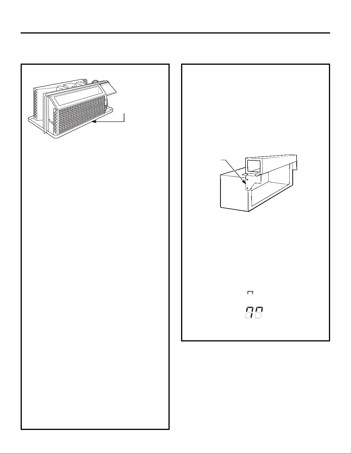
Instrucciones de instalación
¿DESEA CAMBIAR UNA UNIDAD YA INSTALADA?
Verifique la etiqueta
de “Elementos
esenciales”para
obtener información
importante.
Utilice el montante de pared correcto
Esta unidad está diseñada para instalarse en un
montante para pared de plástico de GE o en uno
de metal con aislamiento. Esto minimiza la
condensación que podría formarse en el lado
del montante que da a la habitación.
Si el montante de pared actual todavía no está aislada, se
puede reducir la posibilidad de condensación mediante la
instalación del equipo de aislamiento RAK901L, disponible
en donde haya adquirido su acondicionador.
NOTA: Hay varios orificios adicionales en los rebordes
laterales de la unidad para instalación en montantes de
pared diferentes a GE. Para evitar dañar el aislamiento
del reborde, el instalador deberá usar un punzón u otra
herramienta filosa para perforar el aislamiento en los
orificios correctos antes de instalar los tornillos del
accesorio.
Utilice la parrilla externa correcta
Se deben utilizar las parrillas externas descriptas en
la etiqueta de “Elementos esenciales” en la bandeja
de la base.
• Si no se reemplaza una parrilla existente, su capacidad
y eficiencia se verán reducidas y la unidad no podrá
funcionar correctamente o se romperá en forma
prematura. Un kit deflector, RAK40, puede utilizarse
con parrillas que no fueron diseñadas para las nuevos
acondicionadores Zoneline de GE. El RAK40 contiene
deflectoresde aire y juntas quese colocan sobre la
unidad, a fin de enviar la salida de aire caliente en una
dirección diferente a la toma de aire, y de ese modo
permitir que la unidad funcione correctamente. La parrilla
debetenerun árealibredeporlomenos 65%.
• Debe retirarse cualquier tipo de deflector vertical
ubicado en la parrilla trasera a fin de evitar la
recirculación de aire del condensador que podría
provocar un “encendido y apagado inmediato” de la
unidad y generar fallas prematuras en loscomponentes.
Cómo reemplazar una unidad instalada
con conductos
Una nueva instalación conconductos:
Si esta unidad debe instalarse con una nueva aplicación
con conductos mediante un kit adaptador, éste último
debe instalarse antes de que el acondicionador sea
colocado en el montante de la pared. Las instrucciones
de instalación están incluidas en el kit.
Kits de conductos disponibles:
RAK6052
RAK601/602
Placa de
montaje
La instalación de unaunidad conconductos ya
instalada:
El reemplazo de una unidad con conductos puede requerir
diferentes componentes. Solicite esta información a su
representante de ventas.
• Para reemplazar unidades de 230/208 voltios:
Ver página 13.
• Para reemplazar unidades de 265 voltios:
Ver páginas 14.
Cuando utilice un kit de conductos, usted siempre debe
encender (ON) el Modo 7 " ". Ver las instrucciones de
Modo en la página 7.
Modo para conductos
se muestra encendido (ON)
Conducto
Montante
Utilice el cable de energía correcto
Los códigos locales pueden exigir el uso de dispositivos
de detección de arcos o de fuga de corriente en
instalaciones de 230/208 voltios.
12
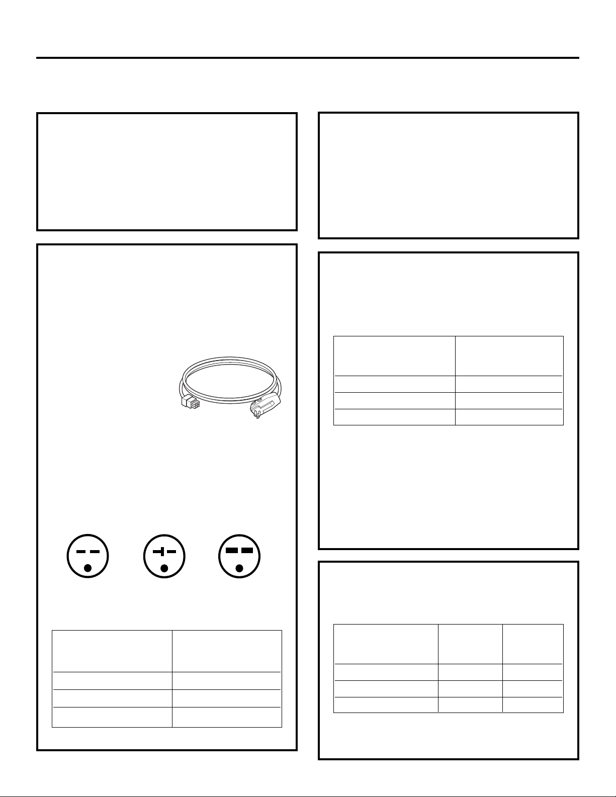
Instrucciones de instalación
OPCIONES DE CONEXIÓN ELÉCTRICA DE 230/208 VOLTIOS
CÓMO REALIZAR
LA CONEXIÓN
1 Retire el gabinete del ambiente.
2 Conecte al suministro de energía.
3 Revise los siguientes pasos para constatar el voltaje.
4 Vuelva a colocar el gabinete del ambiente.
Los cables de alimentación pueden incluir un
dispositivo para interrupción de arco o uno para
interrupción y detección de fuga de corriente. Se
incluye un botón de prueba y de reinicio en el
dispositivo. El dispositivo debe ponerse a prueba
periódicamente: primero se presiona el botón de
TEST (prueba) y luego RESET (reinicio). Si el botón
TEST no se dispara o si el botón RESET no queda
enganchado, deje de utilizar el acondicionador de
aire Zoneline y comuníquese con un técnico calificado.
CONEXIÓN DE CABLE DE
ENERGÍA
Debe utilizarse un kit de suministro de energía con
dispositivo LCDI para suministrarenergíaa la unidad
Zoneline. Se debe obtener el kit adecuado según el voltaje,
la forma de conexión eléctrica y el amperaje del circuito
de lazona.
Las conexiones de circuitos
de 208 o 230 voltios pueden
realizarse con un kit de
suministro de energía o
un kit de caja de conexiones.
Todos los cables, incluyendo
la instalación del receptáculo,
deben ajustarse a los códigos,
ordenanzas y regulaciones locales y del NEC.
Los códigos requerir el uso de un dispositivo de
detección de arcos o de fuga de corriente en el cable
de alimentación con excepción de una conexión
directa. Asegúrese de elegir el cable correcto para
su instalación.
La apariencia puede cambiar.
Kit de suministro de energía
CONEXIÓN DE
SUB-BASE ELÉCTRICA
Los modelos de 230/208 voltios pueden instalarse
utilizando una de las siguientes sub-bases eléctricas:
Clasificación de circuito
derivado y amperaje Kit adecuado
de la unidad de sub-base GE
15 RAK204D15P
20 RAK204D20P
30 RAK204D30P*
*Nose ha aprobadoel uso en modelos de 7000BTU.
Las sub-bases eléctricas otorgan un recinto para
conexiones directas o receptáculos cerrados. El kit
de sub-base incluye el cable de energía.
Las instrucciones incluidas en el kit de sub-base
seleccionado deben seguirse al pie de la letra. Es la
responsabilidad del instalador asegurar que la conexión de
los componentes se realice respetando estas instrucciones
y todos los códigos de electricidad.
Tándem
15 amp.
Configuración de receptáculo de 230/208 voltios.
Clasificación de circuito
derivado y amperaje Cable de energía GE
de la unidad con dispositivo LCDI
*No se ha aprobado el usoen modelos de 7000 BTU.
Perpendicular
20 amp.
15 RAK3153
20 RAK3203
30 RAK3303*
Tándem grande
30 amp.
13
CONEXIÓN DIRECTA
Solicite el siguiente kit para una conexión directa
de 230/208 voltios según se requiera:
Clasificación de circuito Accesorio Kit de
derivado y amperaje de
de la unidad
15 RAK4002A RAK4157
20 RAK4002A RAK4207
30 RAK4002A RAK4307*
*No se ha aprobado el usoen modelos de 7000 BTU.
Salte a la sección “REALIZAR LA CONEXIÓN ELÉCTRICA
A LA UNIDAD”.
suministro suministro
de energía de energía

Instrucciones de instalación
OPCIONES DE CONEXIÓN ELÉCTRICA DE 265 VOLTIOS
ADVERTENCIA:
La conexión de este producto de 265 voltios de CA a un
circuito derivadoDEBE realizarse mediante una conexión
directa de acuerdo a las indicaciones del NEC. El código no
permite enchufar esta unidad a una cajaexterna.
Estos modelos deben instalarse utilizando el kit de GE
de suministro de energía adecuado para el amperaje de
circuito derivado y el vatiaje deseado para el calefactor
de resistencia eléctrica. Utilice la TABLA DE CONEXIONES
ELÉCTRICAS en la página 17 para determinar cuál es el kit
necesario. Debe utilizarse uno de los siguientes métodos
de instalación (A o B):
A. PARA INSTALACIÓN DE SUB-BASE
Loskits de sub-base eléctrica se encuentran disponibles a fin
de proveerun recinto flexible para las conexiones directas.
Clasificación de circuito
derivado y amperaje Kitadecuado
de la unidad de sub-base GE
15 RAK204E15 RAK5172
20 RAK204E20 RAK5202
30 RAK204E30 RAK5302*
Kit de
suministro
de energía
B. PARA INSTALACIÓN DE CONEXIÓN
DIRECTA
Si no se utiliza una sub-base eléctrica, debe realizarse una
conexión directa con el cableado de circuito derivado dentro
de la caja de conexiones segúnlos siguientes pasos.
Solicite el siguiente kit para una conexión directa
de 265 voltios según se requiera:
Clasificación de circuito
derivado y amperaje
de la unidad
15 RAK5157
20 RAK5207
30 RAK5307*
*No se ha aprobado el usoen modelos de 7000 BTU.
Pase a la sección “REALIZAR LA CONEXIÓN ELÉCTRICA
A LA UNIDAD”.
NOTA: Solicite el kit RAK4002CW para una rápida
desconexión dentro de la caja de conexiones.
Kit de
suministro
de energía
*No se ha aprobado el usoen modelos de 7000 BTU.
Las instrucciones incluidas en el kit de sub-base
seleccionado deben seguirse al pie de la letra.
Es la responsabilidad del instalador asegurar que
la conexión de los componentes se realice respetando
estas instrucciones y todos los códigos de electricidad.
14
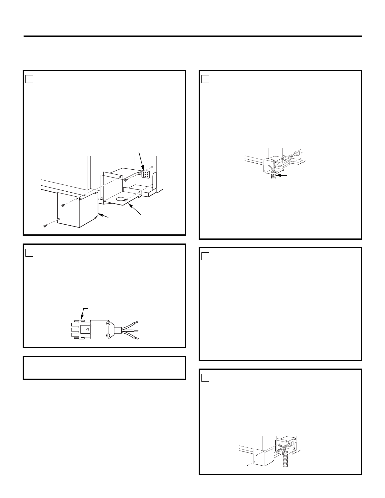
Instrucciones de instalación
REALIZAR LA CONEXIÓN ELÉCTRICA A LA UNIDAD
1
RETIRE LA CAJA DE CONEXIONES
Para retirar la tapa de la caja de conexiones, primero
1
quite los dos tornillos frontales.
2 Para retirar la caja de conexiones, quite los tornillos
posterioressuperiores e inferiores. Observe cómo
las pestañas en el lado izquierdo inferior de la caja
de conexiones sirven para mantener el lado en
su lugar. Esta información le servirá para volver
a instalar la caja.
Conector de la unidad
Caja de
conexiones
2
CONECTE EL CONJUNTO
Tapa de
la caja de
conexiones
DE CABLES
Enchufe el conector provisto en el Kit de
Conexión Directa completamente en el conector
de acoplamiento de la unidad. Asegúrese de que
las pestañas de fijación de los costados estén
encastradas.
Conector
3
CONECTE EL CONDUCTO
PARA CABLES
1 Utilice el orificio redondo ubicado en la parte
inferior de la caja de conexiones para conectar
el conducto de cables que proviene del circuito
derivado. Retire la tapa del orificio, ajuste el
conducto y acerque los cables hacia el interior
de la caja de conexiones. Deje 6″ libres de cable
al final del conducto para que puedan realizarse
las conexiones.
Conducto para cables
2 Si se van a utilizar fusibles y portafusiles, el orificio
de la parte superior de la caja está destinado para
instalar un portafusiles Buss. Asegúrese de que el
fusible y el portafusiles tengan la misma potencia
de servicio que el circuito derivado. Las terminales
del fusible pueden soldarse en el lugar o conectarse
medianteun conectora presión hembra(receptáculo)
de1/4″ listado enUL. Sigalos códigos locales.
4
VUELVA A INSTALAR LA CAJA DE
CONEXIONES
• Para volver a instalar la caja de conexiones, encaje
las pestañas izquierdas en la cara derecha inferior
en la unidad, alineando los orificios de los tornillos en
la parte superior e inferior, y atornille los dostornillos
hasta que el sistema quede asegurado. Asegúrese de
que todos los cables hayan quedado dentro de la caja
y que no estén enganchados entre la caja y la unidad.
El cable a tierra verde de la unidad DEBE estar
conectado al cable a tierra del circuito derivado.
Realice todas las conexiones de cables utilizando
técnicas o conectoresapropiados listados en UL (negro
con negro, blanco con blanco y verde con verde).
NOTA: Solicite el kit RAK4002CW para una rápida
desconexión dentro de la caja de conexiones.
15
5
VUELVA A INSTALAR LA TAPA DE LA
CAJA DE CONEXIONES
1 Con cuidado deposite todos los cables y conexiones
dentro de la caja de conexiones. Asegúrese de que no
hayan quedado conexiones sueltas o cables
expuestos sin aislamiento.
2 Coloque la tapa de la caja de conexiones en su lugar.
Reponga los dos tornillos y ajuste bien.

Instrucciones de instalación
TABLA DE CONEXIONES ELÉCTRICAS
Conexiones de cable de energía
Kits para
suministro
de energía de
230/208 voltios
con dispositivo Configuración
de detection de de enchufe Dispositivo de Vatiaje de calefactor
fuga de corriente de pared protección de circuito
RAK3153 Tándem Fusible de tiempo retardado/ 2,55/2,09 KW
disyuntor de 15 amp
RAK3203 Perpendicular Fusible de tiempo retardado/ 3,45/2,82 KW
disyuntor de 20 amp
RAK3303* Tándem grande Fusible de tiempo retardado/ 5,00/4,10 KW
disyuntor de 30 amp
Conexiones directa
Kits para
suministro
de energía de Dispositivo de Vatiaje de calefactor
230/208 voltios protección de circuito
RAK4157 Fusible de tiempo retardado/disyuntor de 15 amp 2,55 KW/2,09 KW
RAK4207 Fusible de tiempo retardado/disyuntor de 20 amp 3,45 KW/2,82 KW
RAK4307* Fusible de tiempo retardado/disyuntor de 30 amp 5,00 KW/4,10 KW
Kits para
suministro
de energía de Dispositivo de Vatiaje de calefactor
265 voltios protección de circuito
RAK5157 Fusible de tiempo retardado/disyuntor de 15 amp 2,55 KW
RAK5207 Fusible de tiempo retardado/disyuntor de 20 amp 3,45 KW
RAK5307* Fusible de tiempo retardado/disyuntor de 30 amp 5,00 KW
@ 230/208
@ 230/208
@ 265
voltios
voltios
voltios
*No se ha aprobado el uso en modelos de 7000 BTU.
16
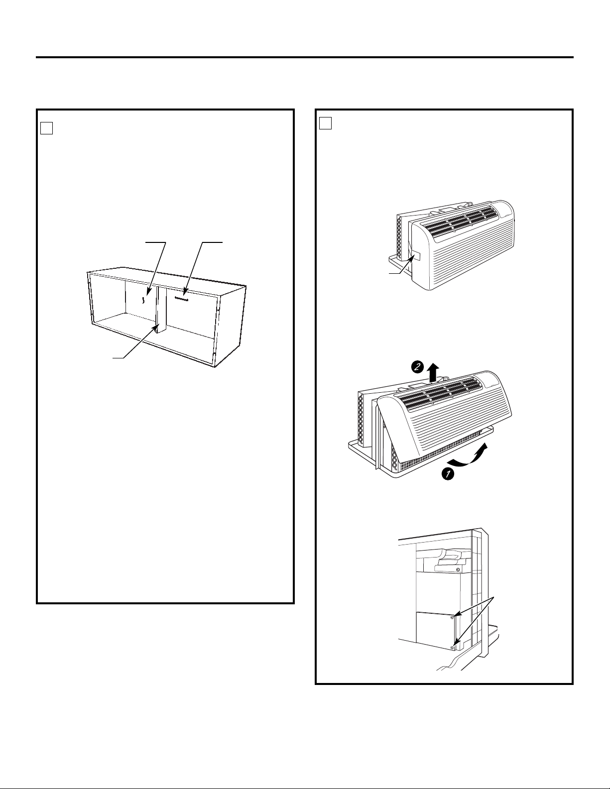
Instrucciones de instalación
CÓMO INSTALAR EL ZONELINE
1
INSTALACIÓN DELMONTANTEDE
PARED Y LA PARRILLA EXTERIOR
Los montantes de pared de la serie RAB71A o
RAB77A4 deben instalarse correctamente mediante
las instrucciones empaquetadas con el montante.
• Retire el refuerzo corrugado y el panel de protección
externo. Utilice la ranura del panel externo como un
lugar para asirse y empuje hacia fuera.
2
CÓMO PREPARAR LA UNIDAD
• Con mucho cuidado, quite la cinta de embalaje
y los bloques de espuma de embalaje del gabinete del
ambiente, el compresor y la puerta de ventilación. Hay
bloques múltiples y pedazos de cinta adhesiva de
envío que necesitan ser removidas.
Panel
protector
Refuerzo
• Instale la parrilla exterior desde el lado de la habitación
siguiendo las instrucciones incluidas en la parrilla.
Ranura
Montante de pared aislado
Esta unidad está diseñada para instalarse con un
montante plástico de GE o un montante de pared
de metal aislante. Estos elementos minimizan la
formación de condensación en la parte que da
a la habitación.
Los montantes de paredde la serie RAB71A tienen
aislamiento. El kit de aislamiento RAK901L se encuentra
disponible para la utilización con RAB77A4 o con
montantes de pared ya instalados que no poseen
aislamiento.
NOTA: Para la instalación con una sub-base o un
adaptador de conductos, ver las instrucciones incluidas
con dichos kits.
Cinta de embalaje
(Las localizaciones
podrían variar)
• Para retirar el gabinete del ambiente, jalede él por la
parte inferior para destrabarlo (1), luego elévelo para
liberar el riel que se encuentra en la parte superior de
la unidad (2).
• Si la puerta de ventilación va a operarse, quite los
tornillos de embalaje del lado delantero de la puerta
de ventilación, si los hubiera.
Quite los tornillos
de embalaje
(si se desea
la operación)
17

Instrucciones de instalación
CÓMO INSTALAR EL ZONELINE (cont.)
3
CÓMO INSTALAR LA UNIDAD
EN EL MONTANTE DE PARED
Deslice la unidad dentro del montante de pared y
asegúrela con cuatro tornillos a través de los orificios del
reborde.
NOTA: Hay varios orificios adicionales en los rebordes
laterales de la unidad para instalación en montantes de
pared diferentes a GE. Para evitar dañar el aislamiento
del reborde, el instalador deberá usar un punzón u otra
herramienta filosa para perforar el aislamiento en los
orificios correctos antes de instalar los tornillos del
accesorio.
4
CÓMO VOLVER A COLOCAR
EL GABINETE DEL AMBIENTE
Para reinstalar el gabinete del ambiente, enganche la
parte superior sobre los rieles de la unidad (1) y luego
empújelo desde la parte inferior (2).
18

Instrucciones de instalación
OPCIONAL: INSTALACIÓN DE UN KIT DE DRENAJE
Los modelos de la serie Dry Air 25 están diseñados para mejorar la dehumidificación en un 25%. Puesto que se absorberá
más humedad del aire, existe una mayor posibilidad de goteo de agua desde la unidad que con un acondicionador
omún. Para prevenir el goteo sobre las paredes externas del edificio, recomendamos el uso del kit de drenaje RAD10.
c
Drenaje externo
Ver las instrucciones de instalación
en el kit RAD10.
Opción: tubo de cobre
de 6″ de largo y 1/2″ de DE
Tubo de drenaje de 1/2″
Orificios de
drenaje cuadrados
de DE
Junta de esponja de neopreno
Placa de montaje de acero
Drenaje interno
Ver las instrucciones de instalación
en el kit RAD10.
Tornillo tipo “A” para montante de metal o
Tornillo tipo “B” para montante moldeado
(El drenaje se encuentra
debajodel gabinete)
Orificios
de drenaje
cuadrados
Junta de esponja de neopreno
Placa de montaje de acero
Tornillo tipo “A” para montante de metal o
Tornillo tipo “B” para montante moldeado
19

Antes de llamar para solicitar servicio…
Solucionar problemas
¡Ahorre dinero y tiempo! Revise las tablas en las siguientes páginas
primero y quizás no necesite llamar a solicitar el servicio.
Problema Causas posibles Qué hacer
El Zoneline no La unidad está desenchufada. • Asegúrese de que el enchufe de Zoneline esté
se enciende insertado completamente.
El cable de energía no se • Retire el gabinete del ambiente y asegúrese de que
encuentra bien enchufado. el conector amarillo al final del cable se encuentre
firmemente enchufado.
El fusible se quemó o • Verifique la caja de fusibles o del disyuntor,
el disyuntor saltó. y cambie los fusibles o reinicie el disyuntor.
La unidad está esperando • Esto es normal. El Zoneline se pondrá en marcha
que se reinicie el protector de nuevo después de haberse reiniciado.
de sobrecarga del compresor.
Corte de energía. • Si hay un corte de energía, configureel control de modo
en STOP (apagado). Cuando vuelva la energía, programe
el control de modo en la configuración deseada.
• Hay una demora protectora (de hasta 3 minutos) para
prevenir la interrupción de la sobrecarga del compresor.
Por esa razón, la unidad reiniciará la refrigeración o
calefacción a los 3 minutos de haber sido encendida
de nuevo.
El dispositivo de interrupción • Presione el botón RESET ubicado en el cable
de corriente se ha activado. de alimentación o la caja cercana al enchufe.
• Siel botón RESET no semantieneen su lugar, no utilice
más el Zoneline y comuníquese conun técnico calificado.
El Zoneline no enfría La circulación de aire interna • Asegúrese de que no haya cortinas, persianas o muebles
o calienta como se encuentra restringida. bloqueando el frente de Zoneline.
corresponde
La circulación de aire externa • Asegúrese de que la parrilla trasera no esté cerrada.
se encuentra restringida o hay Esto puede provocar que la unidad se apague debido
recirculación de aire. al protector de sobrecarga del compresor.
• La parrilla externa debe tener un área libre de por lo
menos 65%. Las parrillas que no son GE pueden ser
demasiado pequeñas para un desempeño adecuado.
Consulte a su vendedor.
El control de temperatura está • Gire el control a una configuración menor o mayor.
mal configurado. NOTA: El limitador de temperatura puede estar acortando
el rango de temperatura.
El filtro de aire está sucio. • Limpie el filtro de airepor lo menos cada 30 días.
Ver la sección Instrucciones de operación.
La habitación estaba muy fría • Cuando recién se enciende, Zoneline necesita un tiempo
o muy caliente. prudencial para enfriar a calentar una habitación.
Está ingresando aire exterior • Configure el control de ventilación en la posición
a la habitación. cerrada.
Sopote al consumidor Solucionar problemas Cuidado y limpieza Operación Seguridad
20
EAppliances.com
G
Problema Causas posibles Qué hacer
Olor a quemado Hay polvillo sobre la • Esto puede provocar olor a “quemado” al comienzo
en el comienzo superficie del elemento de la operación de calefacción. Este olor desaparece
de la operación de calefacción. con rapidez.
de calefacción
El aire no siempre Labomba de calor no está • Esto es normal. La bomba de calor emana aire
está fresco o caliente generando aire caliente. caliente pero no tanto como el aire quese genera cuando
durante la operación se utiliza una calefacción eléctrica de mayor costo.
Los controles auxiliares de • Esto provoca que la ventilación haga circular aire
ventilador inteligente pueden a temperatura ambiente aún cuando el compresor
estar activados en ventilación o calefactor esté apagado. El movimiento de aire
continua. continuo brinda un mejor control de temperatura
global en el modo cool (frío).
Ver Ventilador inteligente—Refrigeración/Calefacción
en la página 5.
El aire no se siente La bomba de calor sola • Utilice la opción de calefacción eléctrica. Esta apaga
lo suficientemente produce aire que se siente la bomba de calor y calefacciona sólo con calor
caliente durante más frío de lo deseado. eléctrico. NOTA: El uso de esta opción provocará un
la operación incremento en el consumo de energía.
de calefacción
Seguridad Operación Cuidado y limpieza Solucionar problemas Soporte al consumidor
La unidad Los controles auxiliares de • Ver la sección Controles auxiliares.
no emite aire ventilador inteligente pueden Ver Ventilador inteligente—Refrigeración/Calefacción
estar configurados para el en la página 5.
ciclo de encendido y apagado.
La calefacción El cable de energía no se • Retire el gabinete del ambiente y asegúrese de que
eléctrica no funciona encuentra bien enchufado. el conector amarillo al final del cable se encuentre
firmemente enchufado.
El visualizador de El compresor puede • Establezca el control de operación en STOP (detener)
temperatura muestra haber fallado. y luego encienda de nuevo la unidad. Si la luz
una luz intermitente intermitente aparece de nuevo en menos de 30 minutos,
llame para solicitar servicio.
21

Estos sonidos son normales.
Sonidos normales de operación
Se puede escuchar un sonido metálico provocado
por el ascenso de agua y su choque contra el
condensador en días lluviosos o cuando hay una
elevada humedad. Esta característica de diseño ayuda
a eliminar humedad y mejorar la eficiencia.
“CLIC”
Demora de
3 minutos
Se pueden escuchar diferentes “clics” cuando los
controles se apagan y encienden o cuando se ajustan
para cambiar la temperatura de la habitación.
En días lluviosos o de elevada humedad se acumula
agua en la bandeja de la base. Elaguapuede
derramarse y gotear desde el lado externo de
la unidad.
El ventilador internofunciona continuamente cuando
la unidadestáoperando en el modo de enfriamiento,
unless the Smart Fan Auxiliary Control is set to cycle.
Esto provocará que el ventiladorse encienda y apague
junto al compresor. También puede escucharse un
ventiladorque se enciende y apaga.
Notará que Zoneline demora unos minutos en volver a
encenderse si se trata de reanudar el funcionamiento
demasiado rápido después de apagarlo o si se ajusta
el termostato segundos después de que el compresor
se haya apagado. Esto se debe a un protector
incorporado del compresor que provoca una demora
de 3 minutos.
Durante el ciclo de descongelado, los ventiladores
SILENCIO
PROTECCIÓN
DEL COMPRESOR
internos y externos se detienen y el compresor
funciona en el modo de enfriamiento para quitar
la escarcha de las serpentinas externas. Después
del descongelamiento, la unidad se reinicia en
calefacción eléctrica para calentar la habitación
rápidamente al nivel de confort deseado.
Para proteger el compresor y para prevenir los
encendidos y apagados inmediatos, la unidad está
diseñada para funcionar por un mínimo de 3 minutos
después de que el compresor se enciende en
cualquier configuración de termostato.
Soporte al consumidor Solucionar problemas Cuidado y limpieza Operación Seguridad
22

Garantía de Zoneline.
Todos los servicios de garantía los proporcionan nuestros Centros
de Reparación de Fábrica o nuestros técnicos Customer Care
®
autorizados. Para concertar una cita de reparación en línea,
visítenos al GEAppliances.com, o llame al 800.GE.CARES
(800.432.2737). Cuando llame para solicitar servicio, por favor
tenga a mano el número de serie y el número de modelo.
Por el período de: GE reemplazará
Un año Cualquier parte del acondicionador de aire que falle debido a defectos en los materiales o en la
A partir de la fecha fabricación. Durante esta garantía limitada de un año, GE también proporcionará, sin costo alguno,
de la compra original toda la mano de obra y el servicio relacionado para reemplazar partes defectuosas.
Cinco años Cualquier parte delsistema de refrigeración sellada (compresor, condensador, evaporador y tuberías
A partir de la fecha de conexión) que fallen debido a defectos en los materiales o fabricación. Durante estos cuatro años
de la compra original adicionales de garantía limitada, GE también proporcionará, sin costo alguno, toda la mano de obra
y el servicio relacionado para reemplazar partes defectuosas.
Cinco años Desde el segundo hasta el quinto añodesde la fecha de compra original, GE reemplazará ciertaspartes
A partir de la fecha que fallen debido a un defecto de los materiales o de la mano de obra. Las partes cubiertas son
de la compra original motores de ventilación, interruptores, termostatos, calefactor, protectores del calefactor, sobrecarga
del compresor,solenoides, placas de circuito, controles auxiliares, termistores, controles de escarcha,
bomba ICR, condensadores, resistencias no lineales y sostén interno del ventilador. Durante estos
cuatro años adicionales de garantía limitada, el comprador se hará responsable de la mano de obra o
de los costos de servicio relacionado.
Lo que GE no cubrirá:
ngrape su recibo aquí.
E
Es necesario una prueba de su
compra original para obtener
servicio bajo la garantía.
Seguridad Operación Cuidado y limpieza Solucionar problemas Soporte al consumidor
■ Viajes de servicio a su ubicación paramostrarle cómo
funciona el equipo.
■ Instalación o entrega inapropiada, o mantenimiento
impropio.
■ Si usted tiene un problema durante la instalación, o
si su acondicionador de aire no tiene la capacidad de
enfriamientoque usted necesita, póngase en contacto con
nuestro distribuidor o instalador.Usted es responsable de
proporcionar las facilidades de conexión eléctrica necesarias.
■ En ubicaciones comerciales, la mano de obra necesaria para
retirar la unidad hacia un lugar para revisión por parte de
un técnico individual.
■ Fallas o daños provocados porla corrosión debido a la
instalación en medio que contenga químicos corrosivos.
■ Reemplazo de fusibles o reajustede los interruptores
de circuito.
■ Fallas del producto provocadas por modificaciones
al producto o debido a un uso irrazonable, o la falta
de un mantenimiento adecuado y necesario.
■ Fallas o daños provocados porla corrosión debido a la
instalación en una región costera, excepto en modelos
tratados con una protección anticorrosiva especial aplicada
en la fábrica, como lo establece el número de modelo.
■ Daño al producto causado por voltaje inapropiado hacia
el equipo, accidentes, incendios, inundaciones o actos
de la natureleza de fuerzamayor.
■ Daños incidentales o consecuenciales a propiedad personal
causados por defectos posibles con esteacondicionador
de aire.
■ Daños después de la entrega.
■ Producto no accesible para facilitar el servicio requerido.
EXCLUSIÓN DE GARANTÍAS IMPLÍCITAS—Su único y exclusivo derecho es la reparación del producto,
tal y como se indica en esta Garantía limitada. Cualquier garantía implícita, incluyendo las
garantías implícitas de comerciabilidad o adecuación para un fin determinado, están limitadas a
un año o el período de tiempo más breve permitido por la ley.
Esta garantía se extiende al comprador original y cualquier comprador posterior de productos comprados para uso dentro
de Estados Unidos y Canadá. Si el producto está situado en un área que no dispone de servicio por parte de un proveedor
de servicio autorizado de GE, podría tener que hacerse cargo de los costes de envío o bien podría solicitársele que lleve
el producto a una centro de servicio de GE autorizado para realizar la reparación. En Alaska, la garantía excluye el costo
de envío o las visitas de servicio a su ubicación.
Algunos estados no permiten la exclusión o las limitaciones de daños incidentales o consecuenciales. Esta garantía da
derechos legales específicos, y usted podría tener otros derechos que variarán de estado a estado. Para saber cuáles son
sus derechos legales, consulte a la oficina de asuntos del consumidor local o la oficina del Attorney General en su localidad.
Garante: General Electric Company. Louisville, KY 40225
23

Soporte al consumidor.
Página Web de GE Appliances GEAppliances.com
¿Tiene alguna pregunta sobre su electrodoméstico? ¡Pruebe la página Web de GE Appliances 24 horas al día,
ualquier día del año! Para mayor conveniencia y servicio más rápido, ya puede descargar los Manuales de los
c
Propietarios, pedir piezas o incluso hacer una cita en línea para que vengan a realizar una reparación.
Solicite una reparación GEAppliances.com
El servicio de expertos GE está a tan sólo un paso de su puerta. ¡Entre en línea y solicite su reparación cuando le
venga bien cualquier día del año! O llame al 800.GE.CARES (800.432.2737) durante horas normales de oficina.
Real Life Design Studio (Estudio de diseño para la vida real)
GE apoya el concepto de Diseño Universal—productos, servicios y ambientes que pueden usar gente de todas
las edades, tamaños y capacidades. Reconocemos la necesidad de diseñar para una gran gama de habilidades
y dificultades físicas y mentales. Para más detalles cobre las aplicaciones de GE Diseño Universal, incluyendo
ideas de diseño para la cocina para personas con discapacidades, mire nuestra página Web hoy mismo. Para
personas con dificultades auditivas, favorde llamar al 800.TDD.GEAC (800.833.4322).
GEAppliances.com
Piezas y accesorios GEAppliances.com
Aquellos individuos con la calificación necesaria para reparar sus propios electrodomésticos pueden
pedir que se les manden las piezas o accesorios directamente a sus hogares (aceptamos las tarjetas
VISA, MasterCard y Discover). Haga su pedido en línea hoy, 24 horas cada día o llamar por teléfono
al 800.626.2002 durante horas normales de oficina.
Las instrucciones descritas en este manual cubren los procedimientos a seguir por cualquier usuario.
Cualquier otra reparación debería, por regla general, referirse a personal calificado autorizado. Debe
ejercerse precaución ya que las reparaciones incorrectas pueden causar condiciones de funcionamiento
inseguras.
Póngase en contacto con nosotros GEAppliances.com
Si no está satisfecho con el servicio que recibe de GE, póngase en contacto con nosotros en nuestra página
Web indicando todos los detalles así como su número de teléfono o escríbanos a:
General Manager, Customer Relations
GE Appliances, Appliance Park
Louisville, KY 40225
Registre su electrodoméstico GEAppliances.com
¡Registre su nuevo electrodoméstico en línea—cuando usted prefiera! El registrar su producto a tiempo le
proporcionará, si surgiera la necesidad, una mejor comunicación y un servicio más rápido bajo los términos de
su garantía. También puede enviar su tarjeta de registro pre-impresa que se incluye en el material de embalaje.
24
 Loading...