


 Loading...
GE Fanuc Automation
Programmable Control Products
Series 90™
Micro PLC
User's Manual
GFK-1065F |
June 1998 |
GFL-002
Warnings, Cautions, and Notes as Used in this Publication
Warning
Warning notices are used in this publication to emphasize that hazardous voltages, currents, temperatures, or other conditions that could cause personal injury exist in this equipment or may be associated with its use.
In situations where inattention could cause either personal injury or damage to equipment, a Warning notice is used.
Caution
Caution notices are used where equipment might be damaged if care is not taken.
Note
Notes merely call attention to information that is especially significant to understanding and operating the equipment.
This document is based on information available at the time of its publication. While efforts have been made to be accurate, the information contained herein does not purport to cover all details or variations in hardware or software, nor to provide for every possible contingency in connection with installation, operation, or maintenance. Features may be described herein which are not present in all hardware and software systems. GE Fanuc Automation assumes no obligation of notice to holders of this document with respect to changes subsequently made.
GE Fanuc Automation makes no representation or warranty, expressed, implied, or statutory with respect to, and assumes no responsibility for the accuracy, completeness, sufficiency, or usefulness of the information contained herein. No warranties of merchantability or fitness for purpose shall apply.
The following are trademarks of GE Fanuc Automation North America, Inc.
Alarm Master |
Field Control |
Modelmaster |
Series One |
CIMPLICITY |
GEnet |
PowerMotion |
Series Six |
CIMPLICITY Control |
Genius |
ProLoop |
Series Three |
CIMPLICITY PowerTRAC |
Genius PowerTRAC |
PROMACRO |
VuMaster |
CIMPLICITY 90–ADS |
Helpmate |
Series Five |
Workmaster |
CIMSTAR |
Logicmaster |
Series 90 |
|
©Copyright 1994—1998 GE Fanuc Automation North America, Inc.
All Rights Reserved.

RFI Standards
The Series 90 Micro PLCs have been tested and found to meet or exceed the requirements of FCC Rule, Part 15, Subpart J. The Federal Communications Commission (FCC) requires the following note to be published according to FCC guidelines.
Note
This equipment generates, uses, and can radiate radio frequency energy and if not installed in
It has been tested and found to comply with the limits for a Class A digital device pursuant to Part 15 of the FCC Rules, which are designed to provide reasonable protection against harmful
residential area is likely to cause harmful interference, in which case the user will be required to correct the interference at his own expense.
The following note is required to be published by the Canadian Department of Communications.
Note
apparatus set out in the radio interference regulations of the Canadian Department of Communications.
GFK-1065F |
iii |
This page was intentionally left blank for pagination purposes . . .
replace with a BLANK SHEET
iv
Preface
The following markings are required to appear in the Series 90 Micro PLC User’s |
for Class I Div 2 |
1.
IS SUITABLE FOR USE IN CLASS I, DIVISION 2, GROUPS A,B,C,D
OR NON-HAZARDOUS LOCATIONS ONLY.
2.WARNING - EXPLOSION HAZARD - SUBSTITUTION OF COMPONENTS MAY IMPAIR SUITABILITY FOR CLASS I, DIVISION 2:
and
ADVERTISSEMENT - RISQUE D’EXPLOSION - LA SUBSTITUTION DE COMPOSANTS PEUT RENDRE CE MATERIEL INACCEPTABLE POUR LES EMPLACEMENTS DE CLASSE I, DIVISION 2.
3.WARNING - EXPLOSION HAZARD - DO NOT
DISCONNECT EQUIPMENT UNLESS POWER HAS
BEEN SWITCHED OFF OR THE AREA IS KNOWN
TO BE NON-HAZARDOUS.
ADVERTISSEMENT - RISQUE D’EXPLOSION -
AVANT DE DECONNECTER L‘EQUIPEMENT,
COUPER LE COURANT OU S‘ASSURER QUE
L‘EMPLACEMENT EST DESIGNE NON DAN-
GEREUX.
v
replace with a BLANK SHEET
vi

Preface
Content of This Manual
This manual provides information necessary to enable you to integrate a Series 90 Micro Programmable Logic Controller (PLC) into a wide variety of control applications. This manual contains descriptions of hardware components, installation procedures, system operation information, and maintenance information for the Series 90 Micro PLC.
Revisions to This Manual
This manual revision (GFK-1065E) incorporates the following changes:
∙A new 14-point Micro PLC, IC693UDD104, is now available. Technical information pertaining to this unit has been added where appropriate.
∙Additional corrections have been made as needed.
Content of This Manual
Chapter 1. Quick Start. Brief procedures for getting the Micro PLC up and running. Includes “Frequently Asked Questions” and “Programming Examples.”
Chapter 2. Introduction. An overview of the Micro PLC functional and physical characteristics. Describes compatibility with other Series 90 PLCs and lists model specifications.
Chapter 3. Installation. Procedures for installing the Micro PLC and preparing the system for use. Included in this chapter are instructions for unpacking, inspecting, and installing the Micro PLC. Instructions are also provided for connecting cables to programming devices.
Chapter 4. Field Wiring. Power and I/O specifications, and wiring information for the Micro PLC.
Chapter 5. Configuration. Configuration and programming using the Logicmaster 90 Micro software or the Hand-Held Programmer.
Chapter 6. High Speed Counters. Features, operation, and configuration of the High Speed
Counter function.
Chapter 7. Analog I/O. Features, operation, and configuration of the Analog I/O function, a feature of the 23-point Micro PLC.
Chapter 8. System Operation. System operation of the Micro PLC. Includes a discussion of the PLC system sweep sequences, the power-up and power-down sequences, clocks and timers, security through password assignment, and the I/O system.
GFK-1065F |
vii |

Preface
Chapter 9. Diagnostics. A guide to troubleshooting the Micro PLC system. Section 1 describes how to use the self-diagnostic LED blink codes. Section 2 describes how the Micro PLC handles system faults.
Appendix A. Instruction Timing. Tables showing the memory size and execution time required for each function.
Appendix B. Reference Types. Listing of user references and references for fault reporting. Also contains tables listing memory locations that are reserved for I/O functions.
Appendix C. PLC/Software Cross Reference. A comparative listing of the instructions and function blocks supported by the Series 90 Micro PLC and the Series 90-20 PLC.
Appendix D. Serial Port and Cables. Description of the serial port, converter, and cables used to connect Series 90 PLCs for Series 90 Protocol (SNP).
Appendix E. Converters. Detailed description of the RS-422/RS-485 to RS-232 Converter for the Series 90 PLCs. Describes the Miniconverter Kit for and the Isolated Repeater/Converter with Series 90 PLCs.
Appendix F. Cable Data Sheets. Data sheets describing each of the Series 90 PLC cable types that are commonly used with the Micro PLC.
Appendix G. Sample Application for PWM and Pulse Outputs. An example of the use of analog I/O through a signal conditioning unit.
Appendix H. Case Histories. Brief summaries of applications that use the Micro PLC.
viii |
Series 90™ Micro PLC User's Manual–June 1998 |
GFK-1065F |

Preface
Related Publications
Logicmaster™ 90 Series 90-30/20/Micro Programming Software User’s Manual (GFK-0466)
Series 90™ -30/20/Micro Programmable Controllers Reference Manual (GFK-0467)
Workmaster® II PLC Programming Unit Guide to Operation (GFK-0401)
Workmaster Programmable Control Information Center Guide to Operation (GEK-25373)
Hand-Held Programmer, Series 90™ -30/20/Micro Programmable Controllers User’s Manual
(GFK-0402)
Series 90™ -30 Programmable Controller Installation Manual (GFK-0356)
Series 90™ -70 Programmable Controller Installation Manual (GFK-0262)
Series 90™ PLC Serial Communications User’s Manual (GFK-0582)
Series 90™ Micro Field Processor User’s Manual (GFK-0711)
Important Product Information, Micro PLC (GFK-1094)
Important Product Information, Micro Expansion Unit (GFK-1474)
Data Sheet, 14-Point Micro PLCs (GFK-1087)
Data Sheet, 28-Point Micro PLCs (GFK-1222)
Data Sheet, 23-Point Micro PLC (GFK-1459)
Data Sheet, Micro Expansion Unit (GFK-1460)
At GE Fanuc Automation, we strive to produce quality technical documentation. After you have used this manual, please take a few moments to complete and return the Reader's Comment Card located on the next page.
Dave Bruton
Senior Technical Writer
GFK-1065F |
Preface |
ix |
Contents
Chapter 1 |
Quick Start........................................................................................................... |
1-1 |
|
What You Will Need ........................................................................................................ |
1-1 |
|
Getting Started .................................................................................................................. |
1-2 |
|
Frequently Asked Questions ............................................................................................. |
1-4 |
|
Programming Examples .................................................................................................... |
1-6 |
Chapter 2 |
Introduction ......................................................................................................... |
2-1 |
|
Compatibility .................................................................................................................... |
2-3 |
|
Functional Description...................................................................................................... |
2-4 |
|
CPU Board.................................................................................................................. |
2-4 |
|
High Speed Counters (IC693UDR011/002/005, IC693UAL006, IC693UDR010) ... |
2-6 |
|
Type A Counters ................................................................................................. |
2-6 |
|
Type B Counter................................................................................................... |
2-6 |
|
DC Output (IC693UDR005/010, UAL006)............................................................... |
2-6 |
|
PWM Output....................................................................................................... |
2-6 |
|
Pulse Output........................................................................................................ |
2-7 |
|
ASCII Output (IC693UDR005/010, UAL006) .......................................................... |
2-7 |
|
I/O Board .................................................................................................................... |
2-7 |
|
Input Circuits.............................................................................................................. |
2-7 |
|
DC Input Circuits (IC693UDR001/002/005/010, UAL006)............................... |
2-7 |
|
AC Input Circuits (IC693UAA003/007)............................................................. |
2-7 |
|
Potentiometer Inputs (All Models)...................................................................... |
2-7 |
|
Output Circuits ........................................................................................................... |
2-8 |
|
Relay Output Circuits (IC693UDR001/002/005/010, UEX011, UAL006) ........ |
2-8 |
|
AC Output Circuits (IC693UAA003/007) .......................................................... |
2-8 |
|
DC Output (IC693UDR005/010, IC693UAL006).............................................. |
2-8 |
|
Analog I/O (IC693UAL006)...................................................................................... |
2-8 |
|
Input/Output Connectors ............................................................................................ |
2-9 |
|
Serial Ports ................................................................................................................. |
2-9 |
|
Serial Communications Protocols ....................................................................... |
2-9 |
|
Port 1 (All Models) ........................................................................................... |
2-10 |
|
Port 2 (23 and 28-Point Models)....................................................................... |
2-11 |
|
Expansion Port (23 and 28-Point Models) ............................................................... |
2-11 |
|
Terminal Strips......................................................................................................... |
2-12 |
|
Status Indicators ....................................................................................................... |
2-13 |
|
Power Supply Board................................................................................................. |
2-13 |
|
Configuration and Programming..................................................................................... |
2-14 |
|
Fault Reporting ............................................................................................................... |
2-14 |
|
Specifications .................................................................................................................. |
2-15 |
Chapter 3 |
Installation ........................................................................................................... |
3-1 |
|
Minimum Hardware Requirements................................................................................... |
3-1 |
|
Unpacking ......................................................................................................................... |
3-1 |
|
Installation Requirements ................................................................................................. |
3-2 |
|
Installation......................................................................................................................... |
3-2 |
|
Mounting a Unit on a DIN Rail .................................................................................. |
3-4 |
GFK-1065F |
xi |

Contents
|
Removing a Unit From a DIN Rail............................................................................. |
3-4 |
|
Grounding Procedures ................................................................................................ |
3-5 |
|
Logicmaster Programming Device Grounding........................................................... |
3-5 |
|
I/O Installation and Wiring......................................................................................... |
3-5 |
|
Powerup Self-test .............................................................................................................. |
3-6 |
|
Normal Powerup Sequence ........................................................................................ |
3-6 |
|
Fast Powerup.............................................................................................................. |
3-7 |
|
Error Detection And Correction................................................................................. |
3-7 |
|
Connecting a Programming Device .................................................................................. |
3-8 |
|
Connecting the Hand-Held Programmer .................................................................... |
3-8 |
|
Connections for Using Logicmaster 90-30/20/Micro Software ............................... |
3-10 |
|
Workmaster II Computer with WSI ......................................................................... |
3-10 |
|
lBM-PC Compatible Computer................................................................................ |
3-10 |
|
Multidrop Serial Data Configuration to Series 90 PLCs.......................................... |
3-12 |
|
Replacing Fuses (AC In/AC Out Models Only) ............................................................. |
3-13 |
|
Expansion Unit Installation............................................................................................. |
3-16 |
|
Micro Expansion Unit .............................................................................................. |
3-16 |
|
Micro Expansion Unit Orientation ........................................................................... |
3-17 |
|
Electromagnetic Compatibility................................................................................. |
3-18 |
|
Physical Order of Different Types of Expansion Units ........................................... |
3-18 |
|
Agency Approvals, Standards, and General Specifications for Series 90 Micro PLC .. |
3-20 |
|
CE Mark Installation Requirements................................................................................ |
3-22 |
Chapter 4 |
Field Wiring......................................................................................................... |
4-1 |
|
Positive and Negative Logic Definitions .......................................................................... |
4-1 |
|
Interface Specifications..................................................................................................... |
4-3 |
|
Model Summaries....................................................................................................... |
4-3 |
|
14-Point DC In/Relay Out/AC Power (IC693UDR001/UEX011) ............................. |
4-3 |
|
14-Point DC In/Relay Out/DC Power (IC693UDR002), 14 Point DC In/DC Out/DC |
|
|
Power (IC693UDD104) ............................................................................................ |
4-4 |
|
14-Point AC In/AC Out/AC Power (IC693UAA003)................................................ |
4-4 |
|
28-Point DC In/DC & Relay Out/AC Power (IC693UDR005).................................. |
4-5 |
|
23-Point DC In/DC & Relay Out/Analog I/O/AC Power (IC693UAL006) ............... |
4-5 |
|
28-Point AC In/AC Out/AC Power (IC693UAA007)................................................ |
4-6 |
|
28-Point DC/DC & Relay Out/DC Power (IC693UDR010) ...................................... |
4-6 |
|
Positive/Negative Logic Inputs (IC693UDR001/002/005/010, UDD00104, UAL006, |
|
|
UEX011)..................................................................................................................... |
4-7 |
|
Potentiometer Analog Inputs (All Models) ................................................................ |
4-8 |
|
High Speed Counter Inputs (IC693UDR001/002/005/010, UAL006) ....................... |
4-9 |
|
Relay Outputs (IC693UDR001/002/005/010, UAL006, UEX011) ......................... |
4-10 |
|
Output Circuit Protection ......................................................................................... |
4-11 |
|
High Speed Counter Outputs (IC693UDR001/002/005, IC693UAL006) ............... |
4-12 |
|
DC Outputs (IC693UDR005/010 and IC693UAL006) ............................................ |
4-12 |
|
Transistor Outputs 24VDC (IC693UDD104) .......................................................... |
4-12 |
xii |
Series 90™ Micro PLC User's Manual–June 1998 |
GFK-1065F |

Contents
|
24 VDC Output Power Supply (IC693UDR001/002/005/010, IC693UDD104, |
|
|
IC693UAL006, IC693UEX011)............................................................................... |
4-14 |
|
Analog Inputs (IC693UAL006)................................................................................ |
4-15 |
|
Analog Output (IC693UAL006) .............................................................................. |
4-16 |
|
AC Inputs (IC693UAA003/007) .............................................................................. |
4-17 |
|
AC Outputs (IC693UAA003/007)............................................................................ |
4-18 |
|
Field Wiring Installation ................................................................................................. |
4-20 |
|
Wire Connection Information................................................................................... |
4-20 |
|
Power Supply and I/O Connections.......................................................................... |
4-20 |
|
General Wiring Procedures ...................................................................................... |
4-21 |
Chapter 5 |
Configuration ...................................................................................................... |
5-1 |
|
Micro PLC Parameters...................................................................................................... |
5-1 |
|
Configuration and Programming Using the HHP ............................................................. |
5-4 |
|
HHP Configuration Screens ....................................................................................... |
5-4 |
|
Storing the User Program Using the HHP.................................................................. |
5-7 |
|
Storing Configuration and Register Data Using the HHP.......................................... |
5-8 |
|
Other HHP Functions ................................................................................................. |
5-8 |
|
Clearing User Memory Using the HHP...................................................................... |
5-8 |
|
Booting up in Stop Mode Without Clearing Memory ................................................ |
5-9 |
|
Setting the Time of Day Clock (23 and 28-Point PLCs) ............................................ |
5-9 |
|
Configuration and Programming Using Logicmaster 90 Software................................. |
5-10 |
|
Configuring Serial Ports ................................................................................................. |
5-12 |
|
Logicmaster 90 Configuration of Serial Port 2 ........................................................ |
5-13 |
|
Configuring Serial Ports Using the COMM_REQ Function.................................... |
5-15 |
|
Command Block....................................................................................................... |
5-15 |
|
Example ................................................................................................................... |
5-18 |
|
Programmer Attach Feature (14-Point Micro PLCs) ............................................... |
5-20 |
|
Configuring ASCII Output.............................................................................................. |
5-21 |
|
Autodial Command Block ........................................................................................ |
5-21 |
|
Put String Command Block ...................................................................................... |
5-23 |
|
Status Word for Custom Protocol COMM_REQs ................................................... |
5-25 |
|
Configuring Expansion Units (23 and 28-Point Micro PLCs)........................................ |
5-26 |
|
Logicmaster Screens for Configuring Expansion Units........................................... |
5-27 |
|
Series 90 Micro 14-Point Expansion Unit................................................................ |
5-28 |
|
14-Point Generic Expansion Unit............................................................................. |
5-28 |
|
Generic Expansion Unit ........................................................................................... |
5-29 |
|
I/O Link Interface Expansion Unit ........................................................................... |
5-30 |
|
HHP Screens for Configuring Expansion Units....................................................... |
5-31 |
|
Configuring Generic Expansion Units ..................................................................... |
5-31 |
|
Configuring Standard Expansion Units .................................................................... |
5-32 |
|
Configuring I/O Link Interface Expansion Units ..................................................... |
5-33 |
|
Reference Error Checking ........................................................................................ |
5-34 |
Configuring Q1 for PWM or Pulse Output (IC693UDR005/010 and IC693UAL006).. 5-35
GFK-1065F |
Contents |
xiii |

Contents
|
PWM Output ............................................................................................................ |
5-36 |
|
Pulse Train Output.................................................................................................... |
5-38 |
|
Configuring of Outputs Q1 to Q5 (IC693UDD104) ................................................ |
5-39 |
|
PWM Output (IC693UDD104) ................................................................................ |
5-40 |
|
Sample Calculation for PWM Output ............................................................... |
5-42 |
|
Pulse Output (IC693UDD104) ................................................................................. |
5-43 |
Chapter 6 |
High Speed Counters .......................................................................................... |
6-1 |
|
High Speed Counter/CPU Interface .................................................................................. |
6-3 |
|
Registers ..................................................................................................................... |
6-3 |
|
Counts per Timebase Register.................................................................................... |
6-3 |
|
Preload Register ......................................................................................................... |
6-3 |
|
Strobe Register........................................................................................................... |
6-4 |
|
Data Automatically Sent by the HSC ......................................................................... |
6-4 |
|
Analog Input (%AI) Data ........................................................................................... |
6-4 |
|
High Speed Counter Status Codes.............................................................................. |
6-5 |
|
Status Bits (%I) .......................................................................................................... |
6-5 |
|
Data Automatically Sent to the HSC (%Q)................................................................ |
6-6 |
|
Output Failure Mode......................................................................................................... |
6-7 |
|
Type A Counter Operation................................................................................................ |
6-8 |
|
Type A Counter Overview ......................................................................................... |
6-8 |
|
Type A Operating Parameters .................................................................................... |
6-9 |
|
Counter Enable/Disable ............................................................................................. |
6-9 |
|
Counter Output Enable/Disable.................................................................................. |
6-9 |
|
Preload/Strobe............................................................................................................ |
6-9 |
|
Count Mode ............................................................................................................. |
6-10 |
|
Count Direction........................................................................................................ |
6-10 |
|
Strobe/Count Edge ................................................................................................... |
6-10 |
|
Counter Time Base................................................................................................... |
6-10 |
|
Count Limits............................................................................................................. |
6-11 |
|
Output Preset Points................................................................................................. |
6-11 |
|
Preload Value........................................................................................................... |
6-13 |
|
Type B Counter Operation.............................................................................................. |
6-14 |
|
A-Quad-B Counting.................................................................................................. |
6-14 |
|
Type B Counter Overview........................................................................................ |
6-15 |
|
Type B Operating Parameters .................................................................................. |
6-16 |
|
Counter Enable/Disable ........................................................................................... |
6-16 |
|
Counter Output Enable/Disable................................................................................ |
6-16 |
|
Preload/Strobe.......................................................................................................... |
6-16 |
|
Count Mode ............................................................................................................. |
6-16 |
|
Strobe Edge.............................................................................................................. |
6-17 |
|
Counter Time Base................................................................................................... |
6-17 |
|
Count Limits............................................................................................................. |
6-17 |
|
Output Preset Points................................................................................................. |
6-18 |
|
Preload Value........................................................................................................... |
6-19 |
|
Configuration .................................................................................................................. |
6-20 |
|
Logicmaster 90 Software.......................................................................................... |
6-24 |
xiv |
Series 90™ Micro PLC User's Manual–June 1998 |
GFK-1065F |

Contents
|
I/O Scanner and Counter Type Configuration.......................................................... |
6-24 |
|
Counter-specific Configuration ................................................................................ |
6-25 |
|
Type A Counter................................................................................................. |
6-25 |
|
Type B Counter................................................................................................. |
6-26 |
|
Hand-Held Programmer............................................................................................ |
6-27 |
|
Configuration Screens Common to A4 and B1-3A4 Configurations ....................... |
6-27 |
|
A4 Counter Specific Screens.................................................................................... |
6-28 |
|
Type B Counter Specific Screens............................................................................. |
6-31 |
|
COMM_REQ Function ............................................................................................ |
6-34 |
|
Command Block....................................................................................................... |
6-34 |
|
Example ................................................................................................................... |
6-38 |
|
Application Examples–RPM Indicator ........................................................................... |
6-40 |
|
Example 1 ................................................................................................................. |
6-40 |
|
Example 2 ................................................................................................................. |
6-40 |
|
Application Example — Input Capture .......................................................................... |
6-41 |
Chapter 7 |
Analog I/O............................................................................................................ |
7-1 |
|
Overview ........................................................................................................................... |
7-2 |
|
Configuration .................................................................................................................... |
7-5 |
|
Logicmaster 90 Screens.............................................................................................. |
7-6 |
|
Analog Input .............................................................................................................. |
7-6 |
|
Analog Output............................................................................................................ |
7-6 |
|
HHP Screens............................................................................................................... |
7-7 |
|
Calibration......................................................................................................................... |
7-9 |
|
Default Gains and Offsets .......................................................................................... |
7-9 |
|
Calibration Procedure............................................................................................... |
7-10 |
|
Calibration of Input Channels .................................................................................. |
7-10 |
|
Calibration of Output Channels................................................................................ |
7-11 |
|
Storing Calibration Constants .................................................................................. |
7-12 |
Chapter 8 |
System Operation ................................................................................................ |
8-1 |
|
PLC Sweep Summary ....................................................................................................... |
8-1 |
|
Sweep Time Contribution........................................................................................... |
8-3 |
|
Housekeeping............................................................................................................. |
8-3 |
|
Input Scan .................................................................................................................. |
8-3 |
|
Program Execution..................................................................................................... |
8-4 |
|
Output Scan................................................................................................................ |
8-4 |
|
Programmer Service................................................................................................... |
8-4 |
|
Deviations from the Standard Program Sweep........................................................... |
8-5 |
|
Constant Sweep Time Mode ...................................................................................... |
8-5 |
|
PLC Sweep When in STOP Mode ............................................................................. |
8-5 |
|
Software Structure ............................................................................................................ |
8-6 |
|
Program Structure....................................................................................................... |
8-6 |
|
Data Structure............................................................................................................. |
8-6 |
|
Powerup and Power-Down Sequence ............................................................................... |
8-8 |
|
Powerup Sequence...................................................................................................... |
8-8 |
GFK-1065F |
Contents |
xv |

Contents
|
Power-Down Conditions ............................................................................................ |
8-8 |
|
|
Power Cycle................................................................................................................ |
8-9 |
|
|
Clocks and Timers .......................................................................................................... |
8-11 |
|
|
Elapsed Time Clock ................................................................................................. |
8-11 |
|
|
Time of Day Clock (23 and 28-Point Micro PLCs) ................................................. |
8-11 |
|
|
Watchdog Timer ....................................................................................................... |
8-11 |
|
|
Constant Sweep Timer ............................................................................................. |
8-11 |
|
|
Timer Function Blocks ............................................................................................. |
8-12 |
|
|
Timed Contacts......................................................................................................... |
8-12 |
|
|
System Security |
............................................................................................................... |
8-13 |
|
Overview .................................................................................................................. |
|
8-13 |
|
Password Protection ................................................................................................. |
8-13 |
|
|
Privilege Levels........................................................................................................ |
8-13 |
|
|
Privilege Level Change Requests ............................................................................. |
8-14 |
|
|
OEM Protection ....................................................................................................... |
8-14 |
|
|
I/O System for the Series 90 Micro PLC ........................................................................ |
8-15 |
|
|
I/O Scan Sequence.................................................................................................... |
8-15 |
|
|
Default Conditions for Micro PLC Output Points ................................................... |
8-15 |
|
|
Software Filters ........................................................................................................ |
8-16 |
|
|
Discrete Input Filtering ............................................................................................ |
8-16 |
|
|
|
Discrete Input Filtering Control ........................................................................ |
8-16 |
|
|
Limitations of Discrete Input Filtering.............................................................. |
8-16 |
|
Analog Potentiometer Input Filtering....................................................................... |
8-17 |
|
|
|
Input Settings .................................................................................................... |
8-17 |
|
|
Limitations of Analog Potentiometer Input Filtering ........................................ |
8-17 |
|
Diagnostic Data |
............................................................................................................... |
8-18 |
|
Flash Memory ................................................................................................................. |
|
8-18 |
Chapter 9 |
Diagnostics ........................................................................................................... |
|
9-1 |
|
Powerup Diagnostics......................................................................................................... |
9-2 |
|
|
Faults and Fault Handling ................................................................................................. |
9-3 |
|
|
Fault Handling ............................................................................................................ |
9-3 |
|
|
Classes of Faults ......................................................................................................... |
9-3 |
|
|
System Response to Faults ......................................................................................... |
9-4 |
|
|
Fault Summary References......................................................................................... |
9-6 |
|
|
Fault Reference Definitions........................................................................................ |
9-6 |
|
|
Fault Results............................................................................................................... |
9-8 |
|
|
Accessing Additional Fault Information .................................................................... |
9-8 |
|
|
Special Operational Notes................................................................................................. |
9-9 |
|
|
Technical Help .................................................................................................................. |
|
9-9 |
|
Appendix A |
Instruction Timing................................................................... |
A-1 |
|
Appendix B |
Reference Types ........................................................................ |
B-1 |
xvi |
Series 90™ Micro PLC User's Manual–June 1998 |
GFK-1065F |

Contents
User References ............................................................................................................... |
B-1 |
References for Fault Reporting ........................................................................................ |
B-2 |
Fixed I/O Map Locations ................................................................................................. |
B-3 |
Appendix C PLC/Software Cross Reference .............................................. |
C-1 |
Appendix D Serial Port and Cables............................................................. |
D-1 |
RS-422 Interface .............................................................................................................. |
D-1 |
Cable and Connector Specifications ................................................................................ |
D-2 |
Port Configurations .......................................................................................................... |
D-3 |
Series 90 PLC Serial Port .......................................................................................... |
D-3 |
Workmaster Serial Port ............................................................................................. |
D-5 |
IBM-AT Serial Port ................................................................................................... |
D-6 |
RS-232/RS-485 Converter......................................................................................... |
D-6 |
Serial Cable Diagrams ..................................................................................................... |
D-7 |
Point-to-Point Connections ....................................................................................... |
D-7 |
RS-232 Point-to-Point Connections .......................................................................... |
D-7 |
RS-422 Point-to-Point Connection.......................................................................... |
D-11 |
Multidrop Connections............................................................................................ |
D-12 |
Programmer-to-Series 90 PLC Connections ........................................................... |
D-12 |
PLC-to-PLC Master/Slave Connections.................................................................. |
D-18 |
Appendix E Converters ................................................................................. |
E-1 |
RS-422/RS-485 to RS-232 Converter .............................................................................. |
E-2 |
Features...................................................................................................................... |
E-2 |
Functions ................................................................................................................... |
E-2 |
Location in System .................................................................................................... |
E-2 |
Installation ................................................................................................................. |
E-3 |
Cable Description ...................................................................................................... |
E-4 |
Pin Assignments ........................................................................................................ |
E-5 |
Logic Diagram ........................................................................................................... |
E-6 |
Jumper Configuration ................................................................................................ |
E-7 |
Specifications ............................................................................................................ |
E-8 |
Miniconverter Kit............................................................................................................. |
E-9 |
Description of Miniconverter .................................................................................... |
E-9 |
Pin Assignments ...................................................................................................... |
E-10 |
System Configurations ............................................................................................ |
E-11 |
Cable Diagrams (Point-To-Point) ........................................................................... |
E-11 |
Isolated Repeater/Converter........................................................................................... |
E-13 |
Logic Diagram of the Isolated Repeater/Converter................................................. |
E-15 |
Pin Assignments for the Isolated Repeater/Converter ............................................. |
E-16 |
System Configurations ............................................................................................ |
E-18 |
Simple Multidrop Configuration ............................................................................. |
E-18 |
GFK-1065F |
Contents |
xvii |

Contents
Complex Multidrop Configuration.......................................................................... |
E-19 |
Rules for Using Repeater/Converters in Complex Networks .................................. |
E-19 |
Cable Diagrams ....................................................................................................... |
E-20 |
Appendix F |
Cable Data Sheets ..................................................................... |
F-1 |
IC693CBL303: Hand-Hand Programmer Cable ............................................................... |
F-2 |
|
IC690CBL701: Workmaster (PC-XT) to RS-485/RS-232 Converter Cable .................... |
F-4 |
|
IC690CBL702: PC-AT to RS-485/RS-232 Converter Cable............................................ |
F-5 |
|
IC647CBL704: Workstation Interface to SNP Port Cable ............................................... |
F-6 |
|
IC690CBL705: Workmaster II (PS/2) to RS-485/RS-232 Converter Cable .................... |
F-7 |
|
2-Wire Cable Diagrams..................................................................................................... |
F-8 |
|
Appendix G Sample Application or PWM and Pulse Outputs ................. |
G-1 |
Series 90 Micro PLC Analog I/O Through CALEX Signal Conditioners....................... |
G-1 |
Application....................................................................................................................... |
G-1 |
Solution ............................................................................................................................ |
G-3 |
Example 1 .................................................................................................................. |
G-3 |
Example 2 .................................................................................................................. |
G-4 |
Benefits ............................................................................................................................ |
G-4 |
Sample Ladder Logic Diagram ........................................................................................ |
G-5 |
Appendix H |
Case Histories........................................................................... |
H-1 |
Automotive Industry ........................................................................................................ |
H-2 |
|
Fluid Pumping Control .............................................................................................. |
H-2 |
|
Bakery Industry ................................................................................................................ |
|
H-3 |
Pastry Line Conveyor Control................................................................................... |
H-3 |
|
Chemical Industry ............................................................................................................ |
H-4 |
|
Chemical Pumping Station ........................................................................................ |
H-4 |
|
Commercial Agriculture Industry .................................................................................... |
H-5 |
|
Grain Processing ....................................................................................................... |
H-5 |
|
Commercial Laundry Industry ......................................................................................... |
H-6 |
|
Garment Storage Rail Control................................................................................... |
H-6 |
|
Construction Equipment Industry .................................................................................... |
H-7 |
|
Pipe Measuring System ............................................................................................. |
H-7 |
|
Entertainment Industry..................................................................................................... |
H-8 |
|
Nightclub Entertainment ........................................................................................... |
H-8 |
|
General Purpose Machinery............................................................................................. |
H-9 |
|
Automated Picture Frame Stapler ............................................................................. |
H-9 |
|
Lumber Industry............................................................................................................. |
|
H-10 |
Pallet Rebuilding..................................................................................................... |
H-10 |
|
Material Handling Industry............................................................................................ |
H-11 |
|
Automated Guided Vehicles ................................................................................... |
H-11 |
|
Paper Industry ................................................................................................................ |
|
H-12 |
Gear Pumping Machinery ....................................................................................... |
H-12 |
|
xviii |
Series 90™ Micro PLC User's Manual–June 1998 |
GFK-1065F |

Contents
Petroleum Industry ......................................................................................................... |
H-12 |
Lease Acquisition Control Transfer ........................................................................ |
H-12 |
Packaging Industry......................................................................................................... |
H-13 |
Shrink Wrapping Machine ...................................................................................... |
H-13 |
Videocassette Packaging ......................................................................................... |
H-14 |
Plastics Industry ............................................................................................................. |
H-15 |
Injection Molding .................................................................................................... |
H-15 |
Plastic Parts Manufacturing..................................................................................... |
H-16 |
Public Emergency Services Industry ............................................................................. |
H-17 |
Storm Warning Systems .......................................................................................... |
H-17 |
Sports Equipment Industry............................................................................................. |
H-18 |
Boxing Partner ........................................................................................................ |
H-18 |
Tubing Manufacturing Industry ..................................................................................... |
H-19 |
Tube Bending.......................................................................................................... |
H-19 |
Water and Wastewater Industry..................................................................................... |
H-20 |
Flood Control Monitoring ....................................................................................... |
H-20 |
Sewage/Wastewater Lift Stations............................................................................ |
H-21 |
Wastewater Treatment............................................................................................. |
H-22 |
Water Flow Control................................................................................................. |
H-23 |
Wire Manufacturing Industry......................................................................................... |
H-24 |
Quality Control........................................................................................................ |
H-24 |
Woodworking Industry .................................................................................................. |
H-25 |
Conveyor Chain Lubricator..................................................................................... |
H-25 |
GFK-1065F |
Contents |
xix |

Chapter Quick Start
1
This chapter provides an overview of the steps required to get your Micro PLC set up and running. The Series 90 Micro PLC product line offers models with different capabilities and special features to meet the needs of a wide range of applications. For this reason, you will need to refer to other chapters in this manual for details pertaining to the specific Micro PLC that you have. For summaries of Micro PLC features and specifications for each model, refer to Chapter 2.
No. of I/O Points |
|
|
I/O Configuration |
Power Supply |
Catalog Numbers |
|
|
|
|
|
|
14 |
8 |
DC inputs, 6 relay outputs |
100 to 240 VAC |
IC693UDR001 |
|
|
|
|
|
|
|
14 |
8 |
DC inputs, 6 relay outputs |
12 to 24 VDC |
IC693UDR002 |
|
|
|
|
|
|
|
14 |
8 |
AC inputs, 6 AC outputs |
100 to 240 VAC |
IC693UAA003 |
|
|
|
|
|
|
|
14 |
8 |
DC inputs, 6 DC outputs |
12 to 24 VDC |
IC693UDD104 |
|
14 |
8 |
DC inputs, 6 relay outputs (expansion unit) |
100 to 240 VAC |
IC693UEX011 |
|
|
|
|
|
|
|
23 |
13 |
DC inputs, 1 DC output, 9 relay outputs, |
100 to 240 VAC |
IC693UAL006 |
|
|
2 analog in, 1 analog out |
|
|
||
|
|
|
|
|
|
28 |
16 |
DC inputs, 1 DC output, 11 relay outputs |
100 to 240 VAC |
IC693UDR005 |
|
|
|
|
|
|
|
28 |
16 |
AC inputs, 12 AC outputs |
100 to 240 VAC |
IC693UAA007 |
|
|
|
|
|
|
|
28 |
16 |
DC inputs, 1 DC output, 11 relay outputs |
24 VDC |
IC693UDR010 |
|
|
|
|
|
|
|
What You Will Need
∙One of the Micro PLCs listed above.
∙Logicmaster 90-30/20/Micro software (or Logicmaster 90 Micro software).
∙Programming device and appropriate cables: Workmaster® II or CIMSTAR I industrial computer, an IBM® AT, PS/2® or other MS-DOS compatible Personal Computer (with 386 or higher microprocessor and 2 MB memory), or a Hand-Held Programmer and cable.
∙RS-422 to RS-232 Interface. Logicmaster 90 software can use a Work Station Interface (WSI) board, an RS-422 port, or a standard RS-232 interface with an RS-422 to RS-232 converter. The WSI board is installed in the Workmaster II computer at the factory.
∙Tools for mounting the Micro PLC and connecting field wiring cables.
To run Logicmaster 90-30/20/Micro software, the programmer (computer) will need:
∙At least 4MB of free disk space.
∙At least 520KB (532,480 bytes) of available DOS application memory for the WSI version; at least 564KB (577,536 bytes) of available DOS application memory, or 520 KB and 42 KB of
available High Memory Area, Upper Memory Block, or Expanded Memory. For details, see
the Logicmaster™ 90-30/30/Micro Programming Software User’s Manual |
, GFK-0466. |
GFK-1065F |
1-1 |
1 |
Getting Started
The following procedure outlines the steps required to put your Micro PLC into operation.
Step 1. Unpack the Micro PLC
First, carefully inspect all shipping containers for damage. Unpack the shipping container and verify the contents. Record all serial numbers. For details, see “Unpacking” in Chapter 3.
Step 2. Install the Micro PLC
Mount the Micro PLC on a vertical surface: a wall or panel using screws or on a 35mm DIN rail. The Micro PLC requires a minimum clearance of 1.99 inches (50mm) on each side for cooling.
For details, see “Installation Requirements” and “Installation” in Chapter 3.
Step 3. Connect Ground and Power Wiring
∙For safe operation of your Micro PLC, the installation must meet the requirements of “Grounding Procedures” in Chapter 3.
∙For power connections, refer to the wiring diagram for the Micro PLC model that you have. (See “Field Wiring Installation” in Chapter 4.)
Step 4. Power-up Test
Warning
Ensure that the protective cover is installed over terminals on the terminal board when power is applied to the unit. The cover protects against accidental shock hazard which could cause severe or fatal injury to personnel.
Apply the required power to the system. The Micro PLC should perform a self-diagnostic test. The OK indicator will blink during power-up diagnostics. When self-diagnostics have been successfully completed, the OK indicator will remain lighted. For details, refer to “Powerup Self-test” in Chapter 3.
Step 5. Connect a Programmer to the PLC
Connect a programming device to the RS-422 serial port (Port 1) on the Micro PLC. (Port 2 on 28 and 23-point Micro PLCs does not support configuration and programming.) For cabling diagrams, refer to “Connecting a Programming Device” in Chapter 3.
If Logicmaster 90 software is not installed on your programmer, install it according to the procedures in the Logicmaster™ 90-30/20/Micro Programming Software User’s Manual , GFK-0466.
1-2 |
Series 90™ Micro PLC User's Manual – June 1998 |
GFK-1065F |

1 |
Step 6. Configure the Micro PLC
The Logicmaster 90 configuration function is used to select Micro PLC operating parameters to meet the requirements of your system.
A. Start up your computer in DOS mode.
B. At the DOS prompt, type CD LM90 and press the ENTER key.
C. Type LM90 and press ENTER.
D.When the main menu for the Logicmaster 90 software appears, press SHIFT + F1. A list of PLCs will appear.
E.From the list, select the type of Micro PLC that you have and press ENTER.
F.Press F2. The Software Configuration menu will appear.
For details on configuration, refer to Chapters 5, 6, and 7. When you have finished configuring the Micro PLC, press ESC to return to the main menu.
Step 7. Enter a Ladder Program
A. In the Logicmaster 90 main menu, press F2. The Programming Software menu will appear.
B. Press F1, Program Display Edit. An empty program folder will appear. For details on using the programming software, refer to the Logicmaster 90-30/20/Micro Programming Software User’s Manual , GFK-0466. A sample program for the Micro PLC is provided in the
Series 90™ Micro Programmable Logic Controller Self-Teach Manual , GFK-1104.
Warning
Turn off power to the Micro PLC before connecting field wiring.
Step 8. Connect Field Wiring
Refer to “Field Wiring Installation” in Chapter 4 for general wiring information and wiring diagrams for each Micro PLC model.
GFK-1065F |
Chapter 1 Quick Start |
1-3 |

1 |
Frequently Asked Questions
1.What causes a “No Communications” message when I toggle to MONITOR or ONLINE?
Following are a few possible causes:
∙Insufficient conventional memory (at least 545Kbytes) in your personal computer to load the Logicmaster 90 communications driver.
Make sure the config.sys file in your computer is properly configured. For details on configuring your config.sys file, refer to “Software Installation” in the Logicmaster™ 90 Series 90™- 30/20/Micro Programming Software User’s Manual, GFK-0466. For additional assistance, call your personal computer help line or GE Fanuc PLC Technical Support at 1-800-GEFANUC.
∙Configuration mismatch between Logicmaster 90 in your computer and the PLC configuration.
Make sure that the computer and the PLC are using the same baud rate and parity. From the main menu in Logicmaster 90, press F2 to enter the configuration software. To check the computer settings, press F7, Programmer Mode and Setup, and then F4, PLC Communications Serial Port Setup. To check the PLC settings, press F1, I/O Configuration. The PLC baud rate and parity will be displayed in the Software Configuration Screen.
∙Broken cable between your computer and PLC or broken or missing RS-232/RS-422 converter.
For information on installing the converter, refer to Appendix E in this manual.
2.How do you set up the High Speed Counters (HSCs)?
Using the Logicmaster 90 configuration software or a Hand-Held Programmer (HHP), enable each HSC that you want to use. If you want the HSC to drive an output, you must enable its output in the software configuration and set its Enable Output bit in your program or in the data tables. For example, if HSC 1 is configured with its output enabled and its Output Enable bit, %Q505 is set, it will control Q1. (HSC 1 will continually report to the CPU memory location %AI06.) A sample rung that sets the Output Enable bit for HSC 1 is shown below.
| |
|
|
|FST SCN |
|
|
|%S0001 |
+—————+ |
|
+——] [———————+MOVE_| |
||
| |
| BIT | |
|
| |
| |
| |
| |
| |
| |
| |
+IN |
Q+——————————————————————%Q0505 |
| |
| LEN | |
|
| |
|00003| |
|
| |
+—————+ |
|
For more information, refer to “High Speed Counter/CPU Interface” in Chapter 6 of this manual.
Simple (A-type) counters and A-Quad-B (B-type) HSCs count continuously by default, resetting themselves automatically when a high or low limit is reached. A-type HSCs can also be configured for one-shot counting, in which the HSC counts to one past the limit and then stops.
In one-shot mode, the HSC can be reset by the program using a Communications Request (COMM_REQ) function to write a zero to the Accumulator. The HSC can also be reset by the Preload input. If the counter’s Preload/Strobe parameter is set to PRELOAD (default), the configured preload value will be loaded to the Accumulator when the Preload/Strobe signal goes
1-4 |
Series 90™ Micro PLC User's Manual – June 1998 |
GFK-1065F |

1 |
active. For example, if PRELOAD is configured and the default Preload Value of 0 is used, an input on I2 will reset the Accumulator for HSC 1.
For wiring information, refer to the diagrams in “High Speed Counter Inputs” and the wiring diagrams provided in “General Wiring Procedures” in Chapter 4.
Warning
When the Micro PLC goes from RUN to STOP mode, the HSCs will continue to operate. Also, the HSCs will remain in run mode through a power cycle. Therefore, if an HSC is running when power is lost, it will run when power is restored.
3.How do I program the Micro PLC?
You can use a Hand Held Programmer (IC693PRG300) or Logicmaster 90 software (IC640HWP300, includes a 2-meter programming cable) loaded into a DOS-based personal computer. The personal computer must have at least a 386 processor and at least 2 megabytes of RAM.
For a new-user programming lesson, refer to Appendix A of the Software User’s Manual , GFK-0466. Chapter 4 of the Series 90™-30/20/Micro Programmable Controllers Reference Manual, GFK-0467 provides descriptions and examples of programming commands for the Micro PLC.
4. What should I do when I get a “Password disabled” or “insuff icient privilege” message?
There are two possible causes for these messages:
∙Password is set to DISABLE in the Software Configuration screen for the Micro PLC.
The default configuration for password is ENABLE. When changed to DISABLE and stored to the Micro PLC, the setting is permanent. If the configuration is changed back to ENABLE and stored, the “password disabled” error message will be generated and the store will not be allowed. You can either change the configuration back to DISABLE, or use an HHP to erase the program and configuration, thereby restoring the default configuration.
∙Insufficient privilege has been set in the Software Configuration and stored to the PLC.
The OEM password cannot be overwritten. To remove the OEM password, you must use the HHP to clear the PLC memory.
If a password has been set from the level 4 menu and then forgotten, you can override it. This procedure is documented in Chapter 5 in the Software User’s Manual , GFK-0466. (The original program disks are required.)
5.What does it mean when OK LED is blinking or the Run LED is not lighted?
Each time power is applied, the CPU performs a self check for several seconds. The OK LED blinks during the self-test and then changes to a steady on state.
If the Run LED does not light when you go to run mode, the cause could be invalid configuration or a fatal error in the CPU fault table.
GFK-1065F |
Chapter 1 Quick Start |
1-5 |

1 |
Programming Examples
Test Rung
In the following test rung, an input on I1 will turn on output Q1.
%I1 |
%Q1 |
|—————————| |—————————————————( |
)—| |
On-Delay Timer
In the following LD, the set coil, M0001, turns on the timer, which counts to 5 seconds (00050 x 0.10s) and then activates %M0002. %M0002 turns on the output, %Q0001, activates %M0003 to reset the timer, and resets M0001.
|[ |
START OF LD PROGRAM EXAMPLE |
] |
| |
|
|
|[ |
VARIABLE DECLARATIONS |
] |
| |
|
|
|[ |
BLOCK DECLARATIONS |
] |
| |
|
|
|[ |
START OF PROGRAM LOGIC |
] |
| |
|
|
|FST_SCN |
%M0001 |
|
+——] [——————————————————————————————————-(S)——|
| |
|
|
|
| |
M0001 |
+—————-+ |
%M0002 |
+——] [———————+ONDTR_+————————————————————( )——|
| |
|
|0.10s |
| |
| |
|
| |
| |
|%M0003 |
| |
| |
|
+——] [———————+R |
| |
||
| |
|
| |
| |
| |
CONST —+PV |
| |
|
| |
00050 |
+——————+ |
|
| |
|
%R0001 |
|
| |
|
|
|
|%M0002 |
|
%Q0001 |
|
+——] [——————————————————————————————————( )———|
| |
|
|%M0002 |
%M0003 |
+——] [——————————————————————————————————( )———|
+%M0002 %M0001 +——] [——————————————————————————————————(R)——|
| |
|
|
[ |
END OF PROGRAM LOGIC |
] |
1-6 |
Series 90™ Micro PLC User's Manual – June 1998 |
GFK-1065F |

Chapter Introduction
2
Series 90 Micro PLCs offer an array of useful features, including:
∙Compatibility with Logicmaster 90-30/20/Micro programming software
∙Support for the 90-30 Hand-Held Programmer (HHP)
∙An alarm processor function
∙Password protection to limit access to PLC contents
∙A built-in High Speed Counter (HSC) function that can be configured as four type A counters or as one type B counter and one type A counter (DC in/relay out Micro PLCs only)
∙Two potentiometers that provide selectable analog inputs to %AI16 and %AI17 (with configurable filtering)
∙Configurable software filtering of discrete inputs
∙Series 90 (SNP) and SNP Extended (SNPX), and RTU slave communication protocols
∙A pulse catch input function, selectable on up to four inputs, that detects pulses at least 100 microseconds in width
∙Pulse train and Pulse Width Modulation (PWM) outputs (Micro PLCs with DC output only)
∙Compatibility with 14-point expansion unit (23 and 28-point Micro PLCs)
∙Pager Enunciation function that can be configured to send a specified byte string from Serial Port 2 (23 and 28-point Micro PLCs)
∙Two analog inputs and one analog output (23-point Micro PLC)
GFK-1065F |
2-1 |

2 |
The Micro PLC hardware consists of a single module that includes CPU, I/O, and power supply functions (Figure 2-1). The compact, lightweight unit is designed for 35mm DIN rail or panel mounting.
a45452
|
I1 |
I2 |
I3 |
I4 |
COM1 I5 |
I6 |
I7 |
I8 |
COM2 |
|
2 4 VDC OUT |
|
|
|
|
|
INPUT |
|
|
|
|
|
|
|
|
|
|
|
|
|
|
|
|
|
|
PW R |
|
|
|
|
|
|
|
|
|
|
OK |
|
|
S e rie s |
9 0 |
M i cr o |
||
|
|
|
RUN |
|
||||||
|
|
|
|
|
|
|
|
|
||
|
|
|
INP UT |
|
|
|
|
|
|
|
|
|
|
1 |
2 |
3 |
4 |
5 |
6 |
7 |
8 |
|
|
|
OUT PUT |
|
|
|
|
|
|
|
|
|
|
|
|
PROGRAM MAB LE CONTROLLER |
|||||
100-2 40VAC~ |
|
|
|
|
OUTP UT |
|
|
|
||
L |
H |
|
Q1 |
COM1 |
Q2 |
COM2 |
Q3 |
Q4 |
Q5 |
Q6 COM3 |
Typical 14-Point Micro PLC
a4 5 4 99
|
I1 |
I2 |
I3 |
I4 |
COM1 |
I5 |
I6 |
I7 |
I8 |
COM2 |
I9 |
I1 0 |
I11 |
I12 |
COM3 |
COM3 |
I1 3 |
I1 4 |
I15 |
I1 6 |
COM4 |
COM4 |
24 VD C OUT |
|
|
|
|
|
|
|
|
|
|
INPUT |
|
|
|
|
|
|
|
|
|
|
|
|
|
|
|
|
|
|
|
|
|
|
|
|
|
|
|
|
|
|
|
|
|
|
|
|
|
PW R |
|
|
|
|
|
|
|
|
|
|
|
|
|
|
|
|
|
|
|
|
|
|
OK |
|
|
|
|
|
|
|
|
|
|
|
|
|
|
S e r ie s 9 0 M i cr o |
|
|||
|
|
|
RUN |
|
|
|
|
|
|
|
|
|
|
|
|
|
|
|||||
|
|
|
|
|
|
|
|
|
|
|
|
|
|
|
|
|
|
|
|
|
||
|
|
|
|
|
|
|
|
|
|
|
|
|
|
|
INPUT |
|
|
|
|
|
|
|
|
|
|
INPUT |
|
|
|
|
|
|
|
|
|
|
9 |
10 |
11 |
12 |
13 |
14 |
15 |
16 |
|
|
|
|
1 |
2 |
3 |
4 |
5 |
6 |
7 |
8 |
|
|
|
|
|
|
|
|
|
|
|
|
|
|
|
OUTPUT |
|
|
|
|
|
|
|
|
|
|
7 |
8 |
9 |
10 |
11 |
12 |
|
|
|
|
|
|
|
|
|
|
|
|
|
|
|
|
|
|
OUTPUT |
|
|
|
|
|
|
|
|
|
|
|
|
|
|
|
|
|
|
|
|
|
|
|
|
PROGR AM MAB LE C ON TROLLER |
|||||
1 00-240VAC~ |
|
|
|
|
|
|
|
|
|
OUTPUT |
|
|
|
|
|
|
|
|
|
|
|
|
L |
H |
|
Q1 |
C OM1 |
VC |
Q2 |
Q3 |
Q4 |
Q5 |
COM2 |
Q6 |
COM3 |
Q7 |
COM4 |
Q8 COM5 |
Q9 |
COM6 |
Q10 |
Q11 |
Q12 COM7 C OM7 |
||
Typical 28-Point Micro PLC
Figure 2-1. Series 90 Micro Programmable Logic Controllers
2-2 |
Series 90™ Micro PLC User's Manual – June 1998 |
GFK-1065F |

2 |
Compatibility
∙Logicmaster 90-30/20/Micro software(IC641SWP301, 304, 306, 307), release 8.01 or later
∙Series 90-30 firmware release 5.0 and later
∙Series 90-30 Hand-Held Programmer (IC693PRG300)
∙Series 90 Protocol (SNP and SNPX) and RTU Slave protocol
∙Series 90-20 PLCs (Micro PLCs with relay output – IC693UDR005/010 and UAL006 – only)
Table 2-1. Configuration/Programming Software Versions for Partial Compatibility
|
Store to |
Store to |
Load from |
Load from |
Logicmaster 90 |
Micro Rel. 2 |
Micro Rel. 3 |
Micro Rel. 2 |
Micro Rel. 3 |
Software Version |
or Earlier |
or Later |
or Earlier |
or Later |
|
|
|
|
|
8.00 or later |
No |
Yes |
Yes |
Yes |
|
|
|
|
|
5.01 or later |
Yes |
Yes |
Yes |
No |
|
|
|
|
|
6.01 or later |
Yes |
Yes |
Yes |
No |
|
|
|
|
|
Table 2-2. Micro to Micro Compatibility
Component |
Rel. 3 reads from Memcard |
Rel. 2 reads from Memcard |
|
Written by a Rel. 2 Micro |
Written by a Rel. 3 Micro |
|
|
|
Program |
Yes |
Yes |
|
|
|
Registers |
Yes |
No |
|
|
|
Configuration |
Yes |
No |
|
|
|
Instructions and Function Blocks
The Series 90 Micro PLC supports most 90-30 instruction functions and function blocks. Detailed descriptions and examples of the use of these instructions can be found in the
Logicmaster 90-30/20/Micro Programming Software User’s Manual (GFK-0466), Series 9030/20 Programmable Controllers Reference Manual (GFK-0467), and Hand-Held Programmer, Series 90-30/20/Micro Programmable Controllers User’s Manual (GFK-0402).
See Appendix A for a list of instructions supported by the Series 90 Micro PLC.
GFK-1065F |
Chapter 2 Introduction |
2-3 |

2 |
Functional Description
The Micro PLC contains a CPU circuit board, an I/O board, and a Power Supply board. Figure 2-2 provides an overview of Micro PLC inputs and outputs and of the functions performed by each circuit board.
CPU Board
The CPU contains and executes the user program and communicates with the programmer (HHP or computer running Logicmaster 90-30/90-20/Micro software). The primary capabilities of the Micro PLC CPU hardware are listed in Table 2-3
Table 2-3. CPU Capabilities
14-Point Micro PLCs |
23 and 28-Point Micro PLCs |
|
|
H8/3003 microprocessor running at 9.84Mhz
Powerup reset circuit
Interrupt for power fail warning (2.0 ms)
Internal Coils - 1024
Four configurable 5Khz HSCs
512K x 8 sectored flash memory for operating |
256K x 16 sectored flash memory for operating |
system and nonvolatile user program storage (3K |
system and nonvolatile user program storage (6K |
words of user flash memory) |
words of user flash memory) |
|
|
32 Kbyte RAM backed by super cap (provides data |
64 Kbyte RAM backed by lithium battery |
retention for 3–4 days with the power off at 25°C) |
Real time clock backed up by lithium battery |
|
|
Maximum User Program - 3K words |
Maximum User Program – 6K words |
|
|
Registers - 256 words |
Registers – 2K words |
|
|
Typical Scan Rate: 1.8 ms/K of logic (Boolean |
Typical Scan Rate: 1.0 ms/K of logic (Boolean |
contacts) |
contacts) |
|
|
An RS-422 serial port that supports SNP, SNPX and |
Two RS-422 serial ports: Port 1 supports SNP/SNPX |
RTU Slave protocols |
slave protocols; Port 2 supports SNP/SNPX Slave |
|
and Master protocols and RTU Slave protocol. (Port |
|
2 does not support the HHP.) |
|
|
|
Ability to support up to four expansion units |
|
|
2-4 |
Series 90™ Micro PLC User's Manual – June 1998 |
GFK-1065F |
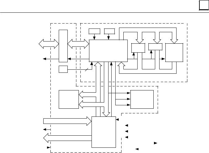
2 |
a 4 5 6 83
|
C lo c k |
R e s e t |
|
|
|
S N P |
|
|
|
|
|
P o rt |
|
|
F la s h |
R A M |
P a r a lle l |
|
|
|
|||
|
|
M ic r o p ro ce s so r |
M e m o r y |
E xp a n s io n |
|
H a n d -h e ld |
|
|
|
|
P o rt |
|
|
|
|
|
|
P ro g ra m m e r |
|
|
|
c o n tro l |
|
P o ts . |
2 |
|
|
|
|
|
|
|
|
|
|
|
|
|
CPU Board |
|
|
|
In p u t s |
P S O K |
P W R |
|
|
IN P U T |
O K |
|
|
||
LEDs |
|
R U N |
LEDs |
|
|
|
R U N |
|
|||
O U T P U T |
O u tp u ts |
O K |
|
|
|
|
|
|
|||
|
|
IN P U T |
|
|
|
|
P S O K |
|
|
|
|
|
|
|
|
|
|
|
|
|
|
|
|
|
|
|
|
|
|
|
|
|
|
|
|
|
|
|
|
|
|
|
|
|
|
|
|
|
|
|
|
|
|||
|
|
|
|
|
|
5 V D C |
|
|
|
|
|
|
|
|
|
|
|
|
|
|
|
|
|
|
|
||
|
|
|
|
|
|
|
|
|
|
|
|
|
|
|
|
|
|
|
|
|
|
|
|
|
|||
|
|
|
|
|
|
|
|
|
|
|
|
|
|
|
|
|
|
|
|
|
|
|
|
|
|
||
2 4 V D C |
|
I/O |
C irc uits |
|
|
2 4 V D C fo r O utp u ts |
|
|
|
||||||||||||||||||
|
|
|
|
|
|
|
|
|
|
|
|
|
|
|
|
|
|
|
|
|
|
||||||
|
|
|
|
|
|
|
|
|
|
|
|
|
|
|
|
|
|
|
|
|
|
||||||
|
|
|
|
2 4 V D C fo r Inp uts |
|
|
|
|
|
|
|
|
|
|
|
|
|
|
|
|
|
|
|
||||
|
|
O U T P U T |
|
|
|
|
|
|
|||||||||||||||||||
|
|
|
|
|
|
|
|
||||||||||||||||||||
|
|
|
|
|
|
|
|
|
|
|
|
|
|
|
|
|
|
|
|
|
|
|
|
||||
|
|
|
|
|
In p u t P o w e r |
|
|
|
|
|
|
|
|
|
|
|
|
|
|
|
|
|
|
|
|
||
|
|
|
|
|
|
|
|
|
|
|
|
|
|
|
|
|
|
|
|
|
|
|
|
|
|||
|
|
|
|
|
|
|
|
|
|
|
|
|
|
|
|
|
|
|
|
|
|
|
|
|
|||
In p u t P o w e r |
|
I/O Board |
|
|
|
|
5 . 1 4 V D C |
|
Pow er Supply Board |
|
|||||||||||||||||
|
|
|
|
|
|
|
|||||||||||||||||||||
|
|
|
|
|
|
|
|||||||||||||||||||||
|
|
|
|
|
|
|
|
|
|
|
|
|
|
|
|
|
|
|
|
|
|
|
|
|
|
|
|
Figure 2-2. Micro PLC Functional Block Diagram
GFK-1065F |
Chapter 2 Introduction |
2-5 |
Loading...