


 Loading...
GE
Transportation
1150 HP AC Drilling Motor,
Model 5GEB22 |
Information |
|||
Document No. GEK-91696, Rev. D |
|
|
||
|
|
|
||
|
|
and |
Confidential |
|
|
Proprietary |
|
|
|
GE |
|
|
|
|
|
|
|
|
|

GEK-91696D
1150 HP AC Drilling Motor, Model 5GEB22
© {2009} General Electric Company. All rights reserved. The information contained in this publication is the property of General Electric Company and is disclosed in confidence. This publication is intended for use by GE customers solely for purposes of operating and performing routine maintenance of purchased or licensed GE products, and it shall not be reproduced, redistributed, retransmitted, translated, abridged, adapted, condensed, revised or otherwise modified, in any form, in whole or in part, or used for any other purpose, or disclosed to third parties, without the express written consent of GE.
GE and Customer agree that the information contained herein does not purport to cover all details or variations in GE products or to provide for every possible contingency with installation, operation or maintenance. Should further information be desired or should particular problems arise that are not covered sufficiently for the user’s purposes, the matter should be referred to General Electric Company. Any applicable Federal, State or local regulations or company safety or operating rules must take precedence over any information or instructions given in the Technical Documentation. GE has no obligation to keep the material up to date after the original publication.
GENERAL ELECTRIC COMPANY EXPLICITLY DISCLAIMS ALL WARRANTIES OF ACCURACY, MERCHANTABILITY OR FITNESS FOR
ANY PURPOSE IN CONNECTION WITH THIS PUBLICATION AND USE THEREOF. |
Information |
|
|
If you are not an authorized recipient of this publication, you are hereby notified that any perusal, use, distribution, copy- |
|
ing or disclosure is strictly prohibited. If you have received this publication in error, please immediately return to GE at the
|
|
Confidential |
following address: GE Transportation, Technical Publications Department, Bui ding 14, 2901 East Lake Rd., Erie, PA 16531. |
||
|
Proprietary |
and |
GE |
|
|
|
|
|
2

|
|
|
|
|
GEK-91696D |
|
|
|
|
|
1150 HP AC Drilling Motor, Model 5GEB22 |
|
|
|
|
|
|
CONTENTS |
|
|
|
|
|
|
|
|
Page |
1. |
GENERAL INFORMATION.......................................................................................................................................................................................... |
|
|
|
4 |
|
1.1. |
INTRODUCTION ........................................................................................................................................................................................................... |
|
|
|
|
4 |
1.2. |
SAFETY INFORMATION.............................................................................................................................................................................................. |
|
|
|
4 |
|
1.3. |
ATEX CERTIFICATION.................................................................................................................................................................................................. |
|
|
|
4 |
|
1.4. INSTALLATION AND OPERATIONAL INSTRUCTIONS |
..................................................................................................................................... |
|
5 |
|||
1.5. MODEL DIFFERENCES ............................................................................................................................................................................................... |
|
|
|
13 |
||
2. |
CONTROLS AND INDICATORS................................................................................................................................................................................ |
|
|
|
13 |
|
3. |
FUNCTIONAL DESCRIPTION ................................................................................................................................................................................... |
|
|
|
13 |
|
4. |
SCHEDULED MAINTENANCE.................................................................................................................................................................................. |
|
|
|
13 |
|
4.1. MONTHLY SCHEDULED MAINTENANCE PROCEDURE................................................................................................................................. |
|
14 |
||||
4.2. CLEANING THE MOTOR ............................................................................................................................................................................................ |
|
|
|
16 |
||
|
|
|
|
|
Information |
|
5. REMOVAL AND REPLACEMENT PROCEDURES ............................................................................................................................................... |
|
|
16 |
|||
5.1. MOTOR PREPARATION FOR SHIPMENT.............................................................................................................................................................. |
|
|
|
16 |
||
5.2. DISASSEMBLY PROCEDURES.................................................................................................................................................................................. |
|
|
|
19 |
||
5.3. INSPECTION AND REPAIR PROCEDURES .......................................................................................................................................................... |
|
|
|
25 |
||
5.4. STEAM CLEANING....................................................................................................................................................................................................... |
|
|
|
|
28 |
|
5.5. |
STATIC ELECTRICAL TESTING.................................................................................................................................................................................. |
|
|
|
29 |
|
|
|
|
|
Confidential |
|
|
5.6. ROTOR SUBASSEMBLY PROCEDURES ................................................................................................................................................................ |
|
|
|
30 |
||
5.7. ROTOR INSTALLATION INTO THE STATOR FRAME ......................................................................................................................................... |
|
|
35 |
|||
5.8. MOTOR BEARING CHECKS AFTER ASSEMBLY................................................................................................................................................. |
|
|
37 |
|||
5.9. FINAL ASSEMBLY OF ROTOR DRIVE END (DE) COMPONENTS ................................................................................................................ |
|
39 |
||||
5.10. FINAL ASSEMBLY OF ROTOR CONNECTION END (CE) COMPONENTS.................................................................................................. |
|
39 |
||||
5.11. ELECTRICAL RUNNING TESTS................................................................................................................................................................................ |
|
|
|
39 |
||
|
|
|
and |
|
|
|
5.12. HUB INSTALLATION |
.................................................................................................................................................................................................... |
|
|
|
40 |
|
6. |
SUMMARY DATA........................................................................................................................................................................................................... |
|
|
|
|
44 |
|
|
Proprietary |
|
|
|
|
6.1. DRILL MOTOR DATA |
.................................................................................................................................................................................................... |
|
|
|
44 |
|
6.2. DRILL MOTOR COMPONENT IDENTIFICATION................................................................................................................................................ |
|
|
46 |
|||
6.3. INSPECTION DATA....................................................................................................................................................................................................... |
|
|
|
|
47 |
|
6.4. SPECIAL TOOLS AND MATERIALS ......................................................................................................................................................................... |
|
|
|
47 |
||
|
GE |
|
|
|
|
|
3

GEK-91696D
1150 HP AC Drilling Motor, Model 5GEB22
1.GENERAL INFORMATION
1.1.INTRODUCTION
This publication provides basic instructions for inspection, maintenance, and overhaul procedures the drilling motor model 5GEB22. Figure 1 represents the 5GEB22 motor with cooling blower and connection box. Figure 2 depicts the 5GEB22 grounding block and rotor lock for shipment. Also included in this publication are special tools and materials required to perform the procedures.
For general drilling motor information, refer to Table 9 in section 6.1.2. Drill Motor General Data in this publication. For drilling motor application data, refer to Table 8 in section 6.1.1. Drill Motor Application Data in this publication. This publication has significant changes since the last release. Due to major changes, there are no revision bars.
|
Confidential |
Information |
and |
|
|
|
|
1.2.SAFETY INFORMATIONProprietary
Safety precautions, which must be observed when working on this equipment, appear throughout this publica-
tion. WARNINGS indicate the potential for personal injury, and CAUTIONS indicate the potential for equipment damage. GE
1.3.ATEX CERTIFICATION
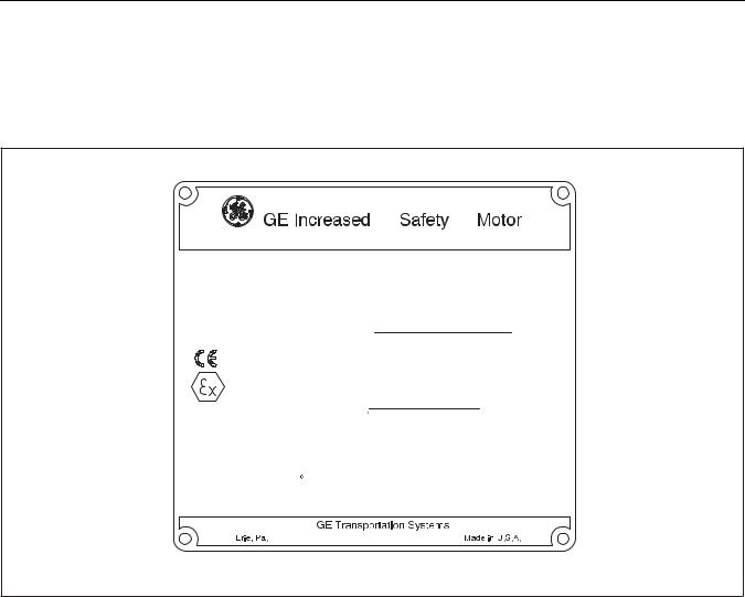
ATEX certification applies only to those motors with the increased safety nameplate shown in Figure 3 .
NOTE: In order to maintain ATEX approval, only GE Transportation original parts shall be used as replacement parts.
Due to format changes, revision bars are not used.
4

GEK-91696D
1150 HP AC Drilling Motor, Model 5GEB22
|
|
Confidential |
Information |
|
and |
|
|
Proprietary |
|
|
|
|
|
|
1.4. |
INSTALLATIONGEFigureAND 2OPERATIONAL. 5GEB22 DrillingINSTRUCTIONSMotor Without Cooling Blower or Connection Box. |
WARNING: Installation shall be in accordance with the instruction as defined in EN 60079–14:2008 “Electrical apparatus for explosive gas atmospheres, Part14. Electrical installation in hazardous areas (other than mines)". Guard for couplings, belts, or chains should be installed as needed to protect against accidental contact with moving parts. Machines accessible to the public should be further guarded by screens, guard rails, etc., to prevent the public from coming in contact with the equipment. Failure to observe these precautions may result in injury or death.
1.This machine is suitable for operation in typical oil well drilling industry rig environments including offshore platforms and mobile drilling units. Use the motor in the correct ATEX category only as indicated in Figure 3 . For other types of applications and environments, please contact your GE representative to determine suitability.
5
GEK-91696D
1150 HP AC Drilling Motor, Model 5GEB22
DRILLING MOTOR MODEL NO. – 5GEB22
SERIAL NO.
COOLING–3000 SCFM AIR SUPPLIED
BY BLOWER UNIT
CLOSED COOLING SYSTEM, IP56, TO MAINTAIN MAX.
INTERNAL AIR TEMPERATURE OF 45 C
|
RATINGS |
|
S9 |
CONTINUOUS |
|
|
AMBIENT AIR MAX |
45 C |
45 C / 55 C |
||
|
PHASE |
|
|
|
3 |
|
AC VOLTS (L-L) |
|
|
587 |
|
|
AMPS AC |
|
1380 |
1120 / 1048 |
|
|
RATER RPM |
|
|
800 |
|
|
SHAFT HP |
|
1400 |
1150 / 1075 |
|
|
MAX. FREQUENCY HERTZ |
|
|
Information |
|
|
|
153 |
|||
|
MAX OPERATING RPM |
|
3000 |
||
|
CONSTANT HP 800–1800 RPM (600 VOLT L–LINE SUPPLY) |
||||
|
WITH 600 VOLTS MAINTAINED ABOVE 820 RPM |
||||
|
CONSTANT HP 800–2400 RPM (690 VOLT L–LINE SUPPLY) |
||||
|
WITH 690 VOLTS MAINTAINED ABOVE 940 RPM |
||||
|
INSULATING CLASS |
|
H |
|
|
|
CONNECTION |
|
Confidential |
|
|
|
|
|
WYE |
||
|
INGRESS PROTECTION |
|
IP44 / 6424 LBS (2914 Kg) |
||
|
Proprietary |
and |
|
IP56 / 7124 LBS (3238 Kg) |
|
GE |
|
|
|
|
|
Figure 3. Safe Electrical Parameters for the 5GEB22 Motor. |
|||||
E-50984
2.It is the end user’s responsibility to ensure that the motor with steel components including shaft, stator frame, stator core, and rotor core, along with the blower and variable speed drive are installed in the correct designated area and will not be subjected to existing (or foreseeable) aggressive destructive substances.
3.Periodic lubrication is not required on model 5GEB22 drilling motor between scheduled overhaul intervals because the bearings are grease packed and permanently sealed. Motor bearings MUST be replaced after 25,000 hours of operation, which is 90% of calculated bearing life. All maintenance must be carried out in accordance with:
a.EN 60079–17:2003— Electrical apparatus for explosive gas atmospheres, Part 17. Inspection and maintenance of electrical installations in hazardous areas (other than mines).
6
GEK-91696D
1150 HP AC Drilling Motor, Model 5GEB22
b.IEC 60079–19:2006 — Electrical apparatus for explosive gas atmospheres, Part 19. Repair and overhaul for apparatus used in explosive atmospheres (other than mines or explosive industry).
4.Safe electrical parameters are defined in Figure 3 and Figure 4 defines the safe environmental parameters for the drilling motor model 5GEB22. The drilling motor may be operated in the presence of typical vibration levels encountered on land and offshore rigs.
CERTIFIED Ex e II T3 (TAMB –40 C to +55
 C)
C)
IEC 60034–1
SIRA 09ATEX3077X |
|
|
|
|
Information |
||
|
|
|
|
|
|||
Year of Construction |
|
||||||
1180 |
|
|
|
|
|
|
|
II 2 G c T3 |
|
|
|
|
|
|
|
Motor Model Number: 5GEB22 |
|
||||||
Maximum Current: |
|
|
1800 AMPS (RMS) |
||||
|
|
|
|
|
|||
|
Confidential |
|
|||||
Ratio Max./Nom. (IA |
/ IN) Curren : 1.36 |
|
|||||
Safe Stall Time: 37 Seconds |
|
||||||
Temperature Protection D vic s Must Be |
|||||||
Set At 190 C (maximum) |
|
||||||
DO NOT OPEN WHEN ENERGIZED |
|||||||
and |
|
|
|
|
|
|
|
1.4.1.Drilling MotorProprietaryModel 5GEB22 Operational Requirements
The drilling motor requires:
1.The cableGEfitted to the equipment must be capable of withstanding maximum temperatures of 230°F (110°C) at the cable entry point. No PVC type insulation is permitted.
2.The equipment must be supplied continuously with at least 3000 Standard Cubic Feet per Minute (SCFM) (84930 SLPM) of cooling air. The cooling arrangements must be suitable for the area in which it is installed. When fitted to the equipment, the cooling arrangements must ensure that the equipment satisfies a degree of protection of at least IP44.
3.RTDs supplied with the motor are to be connected to intrinsically safe circuits to meet compliance of the Ex certification for operation in a hazardous environment. The protective device must be suitably certified as
compliant with the European Directive 94/9/EC as a Safety Related Device. These circuits are to be manually reset only and will trip (stop) the motor at 190 °C (374 °F). E-50985
7

GEK-91696D
1150 HP AC Drilling Motor, Model 5GEB22
1.4.2.5GEB22 Motor Equipped with Closed Loop Cooling System
When the motor is equipped with a closed loop cooling system, the cooling arrangement must ensure that the equipment satisfies a degree of protection of at least IP56. The motor must be used in accordance with the duties defined in this certificate, with the water cooler supplied with coolant in accordance with Table 2 .
TABLE 2. 5GEB22 CLOSED LOOP COOLING OPTIONS
|
Duty |
Minimum Water Flow Rate |
Max. Coolant Temp. (at cooler inlet) |
||
|
|
|
|
|
|
S1 |
(continuous) |
100 US gal/min (378.5 liters/min) |
33.0 |
°C (91.4 °F) |
|
|
|
|
|
||
S1 |
(continuous) |
50 US gal/min (189.2 liters/min) |
25.0 ºC (77 ºF) |
||
|
|
|
|
|
|
S9 |
(Duty A) |
100 US gal/min (378.5 liters/min) |
33.0 |
°C (91.4 °F) |
|
|
|
|
|
||
S9 |
(Duty A) |
50 US gal/min (189.2 liters/min) |
25.0 ºC (77 ºF) |
||
|
|
|
|
|
|
S9 |
(Duty B) |
100 US gal/min (378.5 liters/min) |
37.7 |
°C (99.86 °F) |
|
|
|
|
|
|
|
S9 |
(Duty B) |
88 US gal/min (333.1 liters/min) |
36.0º C (96.8 |
ºF) |
|
|
|
|
|
|
|
S9 |
(Duty B) |
50 US gal/min (189.2 liters/min) |
28.0 |
ºC (82.4 |
ºF) |
|
|
|
|
|
|
|
|
|
|
TABLE 3. 5GEB22 DUTY CYCLES |
Information |
||
|
|
|
|
|
|
|
|
Duty Reference |
|
|
Specification |
|
|
|
|
|
|
|
|
|
|||
A |
|
|
|
120 seconds on at 800 rpm, 1400 HP, 9200 lb/ft torque, followed by 90 seconds on at 80 |
|||
|
|
|
|
rpm, no load. (S9 duty) |
|
|
|
|
|
|
|
|
|||
B |
|
|
|
144 seconds on at 669 rpm, 1150 HP, 9025 lb/ft torque, followed by 116 seconds on at 80 |
|||
|
|
|
|
rpm, no load. (S9 duty) |
Confidential |
|
|
C |
|
|
|
32 seconds on at 800 rpm, 1400 HP, 9200 ft/lb torque, followed by 30 seconds on at 800 |
|||
|
|
|
|
|
and |
|
|
|
|
|
|
rpm, no load. (S9 duty) |
|
|
|
1.4.3. |
Drive Systems Used with the 5GEB22 |
|
|
|
|||
|
The 5GEB22 motor shall be used with one of the drives indicated in Table 4 or as listed in the ATEX certification. |
||||||
|
The drive outputs shall be limited to 1800 amps maximum. |
|
|||||
|
|
GE |
Proprietary |
|
|
|
|
8

|
|
|
|
|
|
|
GEK-91696D |
|
|
|
|
|
|
|
1150 HP AC Drilling Motor, Model 5GEB22 |
||
|
|
|
|
|
|
|
||
|
|
|
TABLE 4. DRIVE SYSTEM LIST. |
|
|
|
||
|
|
|
|
|
||||
MANUFACTURE |
|
|
MODEL |
|
||||
|
|
|
|
|
|
|
||
GE |
|
|
AC2000AW Variable Speed Drive |
|
|
|
||
|
|
|
|
|
|
|
||
Cegelec Bauteil |
|
|
GD3000E AC Drive System |
|
|
|
||
|
|
|
|
|
||||
Unico Inc |
|
|
Type 2400 Series (Part #109341) with or without a smoothing inductor |
|
||||
|
|
|
|
|
|
|
||
|
|
|
Ross Hill Model 6000 |
|
|
|
||
National Oilwell Varco |
|
|
|
|
|
|
||
Ross Hill Model ABB ACS800 manufactured by NOV |
|
|||||||
|
|
|
|
|||||
|
|
|
|
|
|
|
||
|
|
|
ABB ACS600 manufactured by ABB |
|
|
|
||
ABB |
|
|
|
|
|
|
|
|
|
|
ABB ACS800 manufactured by ABB |
|
|
|
|||
|
|
|
|
|
|
|||
|
|
|
|
|
|
|
|
|
|
|
|
|
|
|
Information |
|
|
|
|
|
Compact AC Drive P1030 with or without |
smoothing filter |
|
|||
|
|
|
Compact AC Drive P1180 with or without |
smoothing filter |
|
|||
Offshore & Marine ASA |
Compact AC Drive P1300 with or without a smoothing filter |
|
||||||
|
|
|
|
|||||
|
|
|
|
|
||||
|
|
|
Compact AC Drive P1500 with or without a smoothing filter |
|
||||
|
|
|
|
|
|
|
|
|
M&I |
|
|
Type AC1350 |
Confidential |
|
|
|
|
|
|
|
|
|
|
|
||
|
|
|
Type OIDM G5M-5C00 |
|
|
|
||
Omron |
|
|
|
|
|
|
|
|
|
|
Type OIDM G5M-5900 |
|
|
|
|||
|
|
|
|
|
|
|||
|
|
|
|
|
|
|
|
|
|
|
|
|
and |
|
|
|
|
Stadt Automasjon |
|
Type 875TCX 6G2N0-AFE (limited to 586 Amps) |
|
|||||
|
|
Proprietary |
|
|
|
|
|
|
Stadt/ABB |
|
|
Converter Type 2000-6-AC-2-00 |
|
|
|
||
Alstom |
|
|
MV3000 Converter |
|
|
|
||
|
|
|
6SE7241-IFQ20-3AB0-Z PWM Inverter |
|
|
|||
|
|
|
|
|
|
|
||
Siemens |
GE |
|
6SE704Sinamics1-S120**** (seeBluedriveFigure 5 below) |
|
|
|
||
|
|
|
|
|
|
|
|
|
9
GEK-91696D
1150 HP AC Drilling Motor, Model 5GEB22
SIEMENS DRIVE IDENTIFICATION 6SE7041 - * * * *
RATED CURRENT INDICATOR: 0 = 1000A (M CHASSIS)
2 = 1200A (L OR M CHASSIS)
5 = 1500A (M CHASSIS)
|
DC LINK VOLTAGE INDICATOR: |
|
|
|
|
|
|
|||||
|
V = 930V (690V LINE-LINE) |
|
|
|
|
|
|
|||||
|
|
|
|
|
|
|
|
|||||
|
U = 780V (600V LINE-LINE) |
|
|
|
|
|
|
|||||
|
|
|
|
|
|
|
|
Information |
||||
|
|
|
|
|
|
|
|
|||||
|
|
|
CHASSIS INDICATOR: |
|
||||||||
|
|
|
|
|
|
|
|
|
||||
|
|
|
M |
|
|
|
|
|
|
|
|
|
|
|
|
|
|
|
|
|
|
|
|
|
|
|
|
|
L |
|
|
|
|
|
|
|
|
|
|
|
|
|
|
|
|
|
|
|
|
|
|
|
|
|
|
|
|
|
|
|
|
|
|
|
|
|
|
|
|
DIGIT 2 OR 6 |
|
|
|
|
|
||
|
|
|
|
|
|
|
|
|
|
|||
|
|
|
|
|
|
|
|
|
|
|
|
|
|
|
|
|
Confidential |
|
|
|
E-50871 |
||||
|
|
|
|
|
|
|
|
|
|
|
||
|
|
|
|
|
|
|
|
|
|
|
||
|
Figure 5. Siemens Drive Nomenclature. |
|
|
|
|
|
||||||
1.4.4. Grounding Instructions |
|
and |
|
|
|
|
|
|
|
|
|
|
failure in the machine. |
|
|
|
|
|
|
|
|
|
|
||
Grounding motor frames is required to s feguard personnel from electric shock in the event of an insulation |
||||||||||||
|
|
|
|
|
|
|
|
|
|
|
|
|
Proprietary |
|
|
|
|
|
|
|
|
|
|
|
|
WARNING: Failure to properly g ound electrical equipment may expose personnel to a potentially hazardous |
|
|||||||||||
condition in which serious or fatal injury from electrical shock is possible. |
|
|
|
|
|
|||||||
Grounding conductors must be provided between the machine frame and the supporting structure to avoid |
||||||||||||
hazardousmay be standingpotentialGEwhilevoltagetouchingdifferencethe machinebetween the machine frame and the adjacent surface on which a person |
||||||||||||
NOTE: This type of ground connection is referred to in electrical standards as “equipment ground" or “enclosure ground" which is not to be confused with “system" or “circuit" grounding. Drilling drive systems normally do not have an intentional circuit ground connections, except through high impedance detectors.
Grounding conductors must be provided on drilling units on which the construction on the unit and/or installation of the machines does not inherently ensure positive grounding of the equipment. Examples are those portable (modular) platform rigs and land rigs which do not already have ground cables to all machinery structures. Offshore rigs with equipment fastened to the decks by bolting or welding should not require additional grounding. Reference ABS Rules for Building and Classing Steel Vessels, section 4−8−4/23.3 and IEEE Standard 45−2002, Recommended Practice for Electrical Installations on Shipboard, section 21.4.
10
GEK-91696D
1150 HP AC Drilling Motor, Model 5GEB22
1.4.5. Grounding Procedures
The 5GEB22 has a ground block attached to the frame as shown in Figure 2 . The mounting stud is 3/8–16 thread. To attach a ground cable to the ground block:
1. Obtain a 3/8–16 nut and a lockwasher. Also required is a cable lug to fit the ground cable and terminal hole clearance for the 0.375 diameter stud.
2. Prepare a ground conductor (use appropriate size cable per National Electrical Code) long enough to run from the motor frame to an existing ground conductor system or to a suitable equipment ground point as defined by the National Electrical Code Article 250 or other applicable regulation. Check that the system ground detector is also connected to the Common ground point for the rig and make connection if necessary.
3. Install terminal lugs on cable. Remove paint, rust and oil from all surfaces to which the cables are to be attached and bolt the lugs securely to these surfaces. Torque the nut to 25 lb-ft (34 Nm).
4. After installation, protect the ground stud, nut, and cable lug connection from corrosion by applying a rust inhibitor on the exposed components.
1.4.6. Motor Coupling and Alignment |
Information |
|
CAUTION: Be sure to align, or check alignment carefullyConfidentialon either motors or MG sets. Misalignment can cause excessive vibration and damaging forces on shaft and bearings.
Time taken to assure good alignment will be retur ed reduced downtime.
|
|
|
and |
|
On coupled drives, when a motor and driven unit together have four or more bearings, flexible couplings should |
||||
be used to facilitate alignment. Three−bearing construction requires a rigid coupling. |
||||
|
|
|
||
Proprietary |
|
|
||
CAUTION: Careful alignment of m |
chines, when using either solid (rigid) or flexible couplings, is essential to |
|
||
prevent excessive vibration, hot b |
arings, or shaft failures. |
|
||
Couplings must be |
perly sized to be capable of driving maximum machine torque. Interference fits should be |
|||
1.4.6.2. usedV-BeltbetweenDrivesGE motor shaft and coupling.
On V−belt drives, the driving and driven shafts should be located so that they are parallel and the sheaves aligned. If properly aligned, there is minimum wear on the belts and no excessive thrust on the machine bearings. The sheave should be mounted as close as possible to the motor bearings. The following recommendations should be followed concerning the minimum sheave pitch diameter which can be used for the particular motor. The belt manufacturer should be consulted for the maximum speed ratio and belt for the particular application.
The following formula and data can be used to select the MINIMUM allowable sheave diameter from the standpoint of bearing life and shaft stress. A larger sheave will further reduce the shaft stress and bearing loading. This data is based upon the belts being tightened to a maximum total pull of 1.5 times the required transmission load used in the sheave diameter calculation. Belts should never be tightened more than necessary to transmit this torque.
D = HP/RPM X 189000/W
11

GEK-91696D
1150 HP AC Drilling Motor, Model 5GEB22
Where D = Minimum sheave pitch diameter in inches for V-belt application.
HP/RPM = Maximum ratio of horsepower, including overloads, to the speed which that power occurs.
W = Maximum allowable radial load.
Belt−driven machines may be equipped with sliding rails. Proper and constant belt tension is easily maintained and the replacement of belts is simplified. This reduces the operating cost and increases the efficiency. Sliding rails are to be used for floor mounting only.
Belt idlers reduce the life of the belts and should not be used if any other method is available. The belts should never be forced over the sheaves. When the drive is started and operating at full speed and full load, the take−up should be adjusted until only a slight bow appears in the slack side. If slippage occurs after the belt tension has been correctly adjusted, the belts and pulleys have not been chosen properly for the job.
|
|
after a day or two of operation. |
|
|
|
|
Information |
|
|||
|
CAUTION: Over−tightening to avoid this slippage may result in early failures of belts, shafts, a d bearings. |
|
|||||||||
|
|
|
|
|
|
|
|||||
|
|
Belt tension should be checked and adjusted following the belt manufacturer’s recommendations. |
|||||||||
|
|
There is normally a drop in tension during the first 24 to 48 hours of operati . During this "run in" period, the |
|||||||||
|
|
belts seat themselves in the sheave grooves and initial stretch is removed. Belt tension should be rechecked |
|||||||||
|
|
|
|
|
|
|
|
Confidential |
|
|
|
|
|
Matched belts run smoother, look better, and last longer. Long |
r belt life results if the belts and sheaves are kept |
||||||||
|
|
clean and the belts are prevented from rubbing against the b |
lt guards or other obstructions. |
||||||||
|
1.4.6.3. |
|
Grouting |
|
|
|
|
|
|
|
|
|
|
On concrete foundations, a minimum of one inch (25 mm) should be allowed for grouting. |
|||||||||
|
|
|
|
|
|
and |
|
|
|
|
|
|
|
A rich, non−shrink grout should be used. High− grade grout mixtures are available commercially. If the grout |
|||||||||
|
|
|
|
Proprietary |
|
|
|
|
|
|
|
|
|
is to be prepared at the site, |
cement−sand ratio of 1:2 is recommended. Just enough water should be used |
||||||||
|
|
to give a stiff mixture. The cl |
an, but rough surface of the foundation should be wet and the grout rammed or |
||||||||
|
|
puddled under the base. |
|
|
|
|
|
|
|
||
|
1.4.6.4. |
|
Flexible Coupling Al gnm n |
rocedure |
|
|
|
|
|
||
LevelshouldallbemountingcheckedGE baseasfollows:supports before setting the base in position. Before grouting the base, the alignment
1.Remove all coupling bolts and slide the shells back so the hub faces are exposed.
2.Check the coupling hub spacing is in accordance with the outline dimensions with the units in the mechanical center of their end play.
3.Start with the coupling next to the largest unit (usually the motor) or near the middle of multiple units. Check the radial alignment by using a straightedge across the two hubs at vertical and horizontal. Or, clamp a dial indicator to one hub and use the outside diameter of the other member to give indication of the misalignment. Be sure the dial indicator supports do not bend or sag, since this will give inaccurate readings. The maximum variation should not exceed 0.002 inches (0.05 mm).
4.Insert a feeler gage or use the dial indicator at hub faces. Measure the gap between hub faces at 0, 90, 180 and 270 degrees and record. Rotate both shafts together 90 degrees and repeat the gap readings. Continue rotation in 90 degree increments until five sets of readings are taken. The fifth set of readings is a check on
12

GEK-91696D
1150 HP AC Drilling Motor, Model 5GEB22
the first set of readings to assure that data is reliable. The readings should not vary by more than 0.002 inches (0.05 mm) between the four readings taken at each coupling position.
5.Correct the horizontal alignment by shifting frames on the base and the vertical alignment by shimming between the machines and the base.
6.Repeat Steps 2, 3 and 4 on each coupling, working away from the motor or center unit.
7.Recheck the couplings on long sets after completing the above checks, because shimming when checking subsequent units may affect those already checked. After the set has been aligned within the specified limits, the coupling shells may be bolted together.
1.5.MODEL DIFFERENCES
TABLE 5. 5GEB22 MODEL DIFFERENCE INFORMATION
|
|
|
|
|
|
|
5GEB22A1 |
|
Original design 5GEB22. |
Information |
|||
|
|
|
|
|||
5GEB22A2 |
|
Same as 5GEB22A1 except new rotor shaft |
erial. |
|||
|
|
|
|
|||
5GEB22A3 |
|
Same as 5GEB22A2 except new CE bea ing. |
|
|||
|
|
|
||||
5GEB22A4 |
|
Same as 5GEB22A2 except stator terminal alignment. |
||||
|
|
|
||||
5GEB22A5 |
|
Same as 5GEB22A3 except stator terminal alignment. |
||||
|
|
|
|
|
|
|
|
|
|
|
Confidential |
|
|
5GEB22C1 |
|
Same as 5GEB22A2 except shaft lengthened and CE insulated bearing. |
||||
5GEB22D1 |
|
Same as 5GEB22A3 xcept rotor shaft diameter increase. |
||||
5GEB22D2 |
|
Same as 5GEB22D1 except without ABS shaft certification. |
||||
5GEB22D3 |
|
Same as 5GEB22D1 except stator terminal alignment. |
||||
|
|
|
|
|
|
|
|
|
|
and |
|
|
|
5GEB22D4 |
|
Same as 5GEB22D2 except stator terminal alignment. |
||||
|
|
Proprietary |
|
|
|
|
2. |
CONTROLS AND INDICATORS |
|
|
|
|
|
|
Not Applicable to drill motor model 5GEB22. Refer to drive system instruction publications for controls and indi- |
|||||
|
cators. |
|
|
|
|
|
3. |
FUNCTIONAL DESCRIPTION |
|
|
|
|
|
|
Theigneds ModelforGEuse5GEB22in thedrillingoil andmotorgas industryis a forceto power–ventilated,offshorethreeand–phaseland basedalternatingdrilling–currentrigs. Theinductionnormal functionmotordeof- |
|||||
the horizontally mounted 5GEB22A motor is to provide power for the mud pumps and drawworks. The 5GEB22D motor has an oversized shaft and is designed for belted horizontal applications such as mud pumps.
Motor speed is controlled by varying the frequency of the alternating current in the motor stator windings. The direction of rotation of the motor rotor is changed by reversing the phase rotation in the motor stator.
The motor is force ventilated by a blower assembly, meeting IP44. It can also be provided with a closed loop cooling system meeting IP56.
4.SCHEDULED MAINTENANCE
Periodic maintenance should be performed to ensure successful motor operation. The following procedures detail the procedures for Scheduled Maintenance. The motor bearings do not require lubrication between overhaul intervals due to packed grease and permanently sealed bearings.
13

GEK-91696D
1150 HP AC Drilling Motor, Model 5GEB22
NOTE: In order to maintain ATEX approval, only GE Transportation original parts shall be used as replacement parts.
4.1.MONTHLY SCHEDULED MAINTENANCE PROCEDURE
4.1.1.Covers, Seals, and Latches
WARNING: Hazardous voltages are present in this equipment. Follow shutdown procedures to ensure power is not applied to the machine before performing any maintenance procedures. Failure to do so may result in injury or death.
1.Remove all power from the machine before attempting maintenance procedures.
2.Clean the outside of the machine and remove the inspection covers.
WARNING: When using compressed air for cleaning purposes, flying debris and particles may present a hazard to personnel in the immediate area. Personnel should be provided with, and trained in he use of, protective equipment as specified by applicable federal or state safety regulations. Failure to do so m y result in injury or death.
3. |
Use clean, dry compressed air and blow the dirt and dust from the terior of the machine. |
|||
|
|
|
|
Information |
4. |
Check exterior covers to ensure the felt seals are intact. Replace seals if missing, broken, deformed or hard- |
|||
|
ened. |
|
|
|
5. |
Install the covers into position on the machine. Torque the cover bolts to 58 ±2 lb.–ft. (79 ±2,7 Nm). |
|||
4.1.2. Power Cable Inspection |
|
Confidential |
|
|
|
|
|
|
|
During inspection of the power cables |
associated hardware, replace any components that are damaged. |
|||
Inspect the power cables for: |
and |
|
|
|
|
|
|
|
|
1. |
Inspect the cable terminals for discoloration from heat, arc damage, cracks or fractures. Replace terminals |
|||
|
and/or cable if damage s found. |
|
|
|
2. |
Ensure terminal c nnections are tight and arcing is not present. |
|
||
3. |
Proprietary |
|
|
|
foundInspect. GEcable insulation for cracked, worn, cut, bubbled or burnt insulation. Replace the cable if damage is |
||||
4. |
Check cable connection bushings and mounting hardware (such as cable cleats). Replace damaged or miss- |
|||
|
ing hardware. |
|
|
|
5. |
Check the ground cable connection to the motor frame. Ensure the connection is tight on the ground stud. |
|||
4.1.3. Megohmmeter Test
The insulation condition of the motor and cables can be determined by a megohmmeter test. When the high voltage of the megohmmeter test instrument is applied to the power components of the motor circuit, a high ohm reading indicates good insulation quality. Low ohm readings indicate insulation breakdown, moisture/debris contamination, or carbon tracking. To test the power circuit insulation with a megohmmeter:
1. Ensure all the components in the power circuit are not affected by a megohmmeter test. Check the drive system for megohmmeter test procedures or disconnect power cables from the drive system. If cables are
14

GEK-91696D
1150 HP AC Drilling Motor, Model 5GEB22
disconnected for the megohmmeter, make sure the cables are insulated from touching any surrounding surfaces.
2.Connect a lead from the megohmmeter instrument to the motor TA lead.
3.Connect the second lead of the megohmmeter to a cleaned ground connection.
4.Apply a 500 volt megohmmeter test to the power circuit.
5.If the reading is above 2 megohms, the power circuit insulation is satisfactory and proceed to Step 7.
6.If the reading is below 2 megohms, the power circuit insulation is degraded or bad. Perform the following procedures to attempt to raise the ohm reading:
a.Check the power cables for cracks, scuffed or open insulation. Repair or replace the cables if damage is found.
b.Water or dirt/debris contamination may be adversely Informationaffecting the ohm reading. Disconnect the power cables from the motor and retest just the stator leads. If the re ding is still below 2 megohms, the motor will have to be removed for cleaning or repair. Refer to 4.2. CLEANING THE MOTOR in this publication for cleaning instructions.
7.Connect one lead of the megohmmeter to the motor lead TA.
8.Connect the second lead of the megohmmeter to one of the RTD leads (red, white, or white).
9.Apply a 500V megohmmeter test to the circuit.
10.If the reading is greater than 2 megohms, pr ceed to Step 11. If the reading is less than 2 megohms, check the RTD cable for cracked, scuffed,andor open insulation. Repair or replace the cable if damage is found. If no cable damage is found, then the RTD is defective and should not be used.
11.Move the firstProprietarylead of the megohmmeter from the motor TA lead to a cleaned motor frame ground while leaving the second l ad of the megohmmeter connected to one of the RTD leads (red, white, or white).
12.Apply a 500V megohmmeter test to the circuit.
13.If the reading is greater than 2 megohms, proceed to Step 14. If the reading is less than 2 megohms, check thecableRTDGEdamagecable foris found,cracked,thenscuffed,the RTDor isopendefectiveinsulationand. shouldRepair notorreplacebe usedthe. cable if damage is found. If no
14.Repeat Steps 7 through 13 until all the RTD cables have been checked against the stator motor leads and the motor frame.
15.Remove the megohmmeter leads and return all components to operating condition.
4.1.4.Motor Mounting Hardware
Check the motor mounting bolts, nuts, and associated hardware. Ensure the hardware is not missing or loose. Replace missing hardware and tighten loose bolts.Confidential
15

GEK-91696D
1150 HP AC Drilling Motor, Model 5GEB22
4.2.CLEANING THE MOTOR
Cleaning the motor is essential to long–term motor life. When the drilling motor is removed from its machinery, accumulated dirt and oil buildup can be removed. The external motor surfaces can be cleaned by steam cleaning. The internal motor components should not be sprayed with a steam cleaner. To clean the motor:
1.Clean the motor only when the drilling motor is removed from its machinery and power is removed from the motor.
WARNING: Personnel performing cleaning procedures must wear protective clothing, gloves and eye protection. Follow local practices and procedures for cleaning. Failure to do so may result in injury or death.
CAUTION: Alkali and chlorinated hydrocarbon cleaning solutions are not recommended for cleaning drill motors due to the adverse affects on motor insulation. Use of these solutions may cause motor failure or reduced motor life.
CAUTION: Do not spray the internal components of the motor with a steam cleaner. Mois ure contamination may cause motor failure or reduced motor life.
2. |
Cover the motor air inlet and outlet with heavy plastic and tape. Ensure the interior motor components are |
||
|
protected from spray during cleaning |
|
Information |
|
|
|
|
3. |
Steam clean the external surfaces of the motor. Do not direct the spray at motor openings or the plastic |
||
|
covers. Recommended cleaning solutions are: CHEMICAL METHODS, INC., 809 or GE BETZ KLEEN SBC120. |
||
4. |
When steam cleaning is complete, let excess fluid drain from the motor. |
||
5. |
Remove the plastic covers or protective covers and tape from the motor. |
||
|
|
Confidential |
|
WARNING: When using compressed air for cleandning purposes, flying debris and particles may present a hazard to personnel in the immediate area. Pe sonnel should be provided with, and trained in the use of, protective
equipment as specified by applicable federal or state regulators. Failure to do so may result in injury or death.
|
6. Using compressed air, blow out the interior of the motor to remove all dirt, dust and moisture. If necessary, |
|
apply heat to d the motor thoroughly. |
5. |
Proprietary |
REMOVALGEAND REPLACEMENT PROCEDURES |
The following procedures outline the overhaul process. All procedures may not be required even though all are described. Inspection of the components will determine the procedures necessary to return the motor to operation.
Do not order replacement parts from this publication. Refer to the PARTS CATALOG for the motor for the correct replacement part number.
5.1.MOTOR PREPARATION FOR SHIPMENT
The drill motor must be prepared for shipment to prevent damage to components during shipping. The following sections detail rotor locking procedures and packaging for shipment.
16
GEK-91696D
1150 HP AC Drilling Motor, Model 5GEB22
5.1.1.Rotor Locking for Shipment
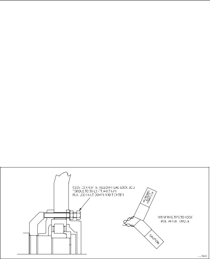
The rotor must be locked in position prior to shipment to prevent damage to bearings and other components of the motor. Figure 2 depicts the 5GEB22 rotor locking arrangement. To lock the rotor for shipment:
1.Remove two diametrically opposite bearing cap bolts and washers (Item 31, Figure 15 ). Place the removed bearing cap bolts and washers into a bag that will be attached to the locking bolt.
2.Thread 0.625–11 x 4.54 in. lock bolts (with jam nuts threaded onto the bolts) into the bearing cap holes as shown in Figure 6 . The lock bolt heads are painted yellow to distinguish the bolts as rotor locking bolts.
3.Torque the rotor locking bolts to 30 lb.–ft. (40,7 Nm). To secure the locking bolts into place, run the jam nuts down to the bearing cap and tighten.
4.Secure the bag containing the two removed bearing cap bolts and washers to the rotor locking bolts as
shown in Figure 2 . |
Information |
5. After motor shipment, the rotor locking bolts must be removed prior to the mo going into service. To
remove the rotor locking bolts: |
|
|
||
a. |
Back the jam nuts away from the bearing cap. |
|||
|
|
|
|
Confidential |
b. |
Remove the bearing cap bolts from the attached b g on the rotor locking bolts. |
|||
c. |
Thread the bearing cap bolts and washers into the bearing cap holes. |
|||
d. |
Torque the bearing cap bolts to 115 ±15 lb.–ft. (156 ±20,3 Nm). |
|||
|
|
|
and |
|
e. Place the removed rotor locking bolts and jam nuts into the bag and store for future motor ship- |
||||
|
ment. |
|
|
|
GE |
Proprietary |
|
|
|
|
|
|
||
Figure 6. Rotor Lock Bolts.
17

GEK-91696D
1150 HP AC Drilling Motor, Model 5GEB22
5.1.2.Motor Packaging for Shipment
After locking the rotor for shipment, the motor should be securely packaged to avoid damage during shipment. To package the motor for shipment:
1.Prepare wood stock of sufficient length to skid the motor as shown in Figure 7 . The yellow pine wood stock must be able to support the approximate 5700 lbs. (2585 kg) weight of the motor (not including the blower and connection box).
2.Drill 1.62 in. (41,2 mm) clearance holes in the wood stock to fit the holes in the motor mounting feet (four holes).
WARNING: The drill motor weighs approximately 5689 lbs. (2580 kg). Use appropriate lifting devices when lifting the motor. Failure to do so may result in injury or death.
3. |
To avoid damage to the motor during handling: |
Information |
|||
|
a. Do not lift the motor by the rotor shaft. |
|
|||
|
b. Do not allow the motor to impact another object when lifted. |
||||
|
|
|
|
Confidential |
|
|
c. Do not wrap the rotor with straps or banding for shipment. Any securing straps or banding should |
||||
|
be wrapped around the motor frame. |
|
|||
4. |
Lift the motor onto the wood frame and align the motor foot holes with the wood frame holes. |
||||
5. |
Install four 1.5–6 in. bolts and washers through the motor mounting feet and wood stock frame. Tighten the |
||||
|
bolt into position. |
and |
|
|
|
|
|
|
|
|
|
6. |
Slush the machined surfaces with rust inhibitor before enclosing the motor for shipment. |
||||
5.1.3. Motor Storage |
Proprietary |
|
|
|
|
The motor should be prepa d for storage to prevent damage.
1.When preparing the motor for storage:
a.Constructinment thisa platformpublicationto.secure the motor as described in section 5.1.2. Motor Packaging for Ship-
b.Slush the exposed machined surfaces with a rust inhibitor.
c.Install wire leads to the anti−condensation heater that allow the heater leads to be connected to an external power source.
d.Install cover and side panel to crate the motor.
e.Apply power to the anti−condensation heater while motor is stored.
18

GEK-91696D
1150 HP AC Drilling Motor, Model 5GEB22
ALLOW CONTAINER
CLEARANCE FROM
MOTOR ON BOTH ENDS
|
Confidential |
Information |
|
|
|
|
|
|
1.5-6 BOLTS, NUTS, AND |
|
|
|
WASHERS, 4 PLACES |
|
|
|
APPROXIMATE WEIGHT OF MOTOR 5689 LBS (2580 KG) |
E-50540 |
|
|
|
|
|
|
|
|
|
2. When removing the motor f omandstorage: |
|
|
|
|
Figure 7. Shipme t Preparation for the 5GEB22 Motor. |
|
|
|
Proprietary |
|
|
a. |
Disconnect pow from the anti−condensation heater. |
|
|
b. |
Rem ve the crating material from the motor. |
|
|
GEc. Remove the rust inhibitor from the machined surfaces. |
|
||
d. |
Visually inspect the motor for excessive rust or other defects. |
|
|
e.Megger the stator leads as described in section 4.1.3. Megohmmeter Test in this publication.
f.If the motor has been in extended storage, the grease in the bearing should be replaced. Follow the overhaul instructions in the following sections to disassemble the motor for bearing access.
5.2.DISASSEMBLY PROCEDURES
5.2.1.Hub Removal
When removing a hub, use a suitable puller, similar to Part 41B535703G1, Figure 32 . This is a simple, efficient hydraulic puller employing the float method of removal. A complete unit consists of a pump kit, a backing plate, an adapter, a felt ring and a bolt.
19

GEK-91696D
1150 HP AC Drilling Motor, Model 5GEB22
NOTE: Do not heat the hub before pulling it, and do not use steel wedges between the hub and bearing cap.
1.Remove the set−screw plug from the tapped hole in the end of the shaft.
2.Screw the backing plate, with felt ring in place, to the end of the shaft as tight as possible by hand. Back off the backing plate to line up the slot with the tapped hole in the end of the shaft. This is to provide sufficient clearance for the hub to pop off.
3.Screw the pressure−fitting adapter into the hole in the shaft until it seats at the bottom.
4.Attach the pump by screwing the connector on one end of the pressure tube into the adapter, and the other end into the pump.
5.Close the hand relief valve and work the pump handle to force oil into the groove in the armature shaft under the hub. When sufficient pressure has been built up, the hub will pop off the shaft and be stopped by the felt washer and backing plate. Information
5.2.2. Rotor Removal
To remove the rotor from the motor assembly:
CAUTION: Special precautions should be taken to av |
damage to the rotor, bearings, or bearing fits when |
|
||||
lifting the rotor in the vertical position or turning the rotor to a horizontal position. |
|
|||||
|
|
|
|
Confidential |
|
|
NOTE: Numbers in parenthesis () refer to item numbers in Figure 15 located in section 6.2. DRILL MOTOR |
||||||
|
|
|
and |
|
|
|
COMPONENT IDENTIFICATION of this publication, unless otherwise noted. |
||||||
1. |
Place the motor in |
ho zontal position. |
|
|
|
|
2. |
Remove the eight b |
lts and flat washers (31) securing the connection−end bearing housing to the connec- |
||||
|
tion−end frame head. Remove the connection−end bearing cap |
|||||
3. |
Proprietary |
|
|
|
|
|
Screwrinne captwoGE(35)longinguideoppositestudsholes(.625of–11theXsix10)justthroughemptiedthe. frameThese headstuds andwill helpinto thetoguideconnectionthe rotor−endoutbearingof the |
||||||
|
motor frame. |
|
|
|
|
|
4. |
Place the motor on a heavy−duty stand with the drive−end up. Level the motor so that the rotor can be lifted |
|||||
|
vertically with a hoist without damaging the bearing or bus rings. |
|||||
5. |
Remove the eight bolts (10) and flat washers holding the drive−end frame head to the motor frame. |
|||||
6. |
Screw a 1 in.−8 steel lifting eyebolt into the threaded hole in the drive−end of the rotor shaft (5). |
|||||
7. |
Align the hoist cable with the center line of the rotor and attach the hoist hook to the lifting eye. |
|||||
NOTE: The connection−end bearing and housing and the drive−end frame head, bearing and housing are removed with the rotor as an assembly.
20
GEK-91696D
1150 HP AC Drilling Motor, Model 5GEB22
CAUTION: Use extreme care when turning the rotor to the horizontal position to avoid damage to the core and the bearing and frame head fits. Use two hoists when positioning the rotor horizontally.
8.Carefully lift the rotor assembly out of the motor stator and place the rotor in a horizontal position on a wooden cradle supporting the core assembly.
9.With the rotor in the horizontal position, remove the two long guide studs (.625–11 X 10) from the connection−end bearing housing.
10.Remove and service the rotor bearings according to instruction in section 5.2.3. Connection End (CE) Bearing Assembly Removal of this publication.
5.2.3.Connection End (CE) Bearing Assembly Removal
There are two Connection End (CE) bearing assemblies used for the 5GEB22 models. Models of the 5GEB22 man-
|
|
ufactured prior to October, 2001 use the original design CE bearing assembly as shown in Figure 8 . 5GEB22 |
|||
|
|
|
|
Information |
|
|
|
models manufactured after September, 2001 ( Figure 9 ) use an enhanced performance CE bearing assembly. |
|||
|
|
Refer to section 6.2. DRILL MOTOR COMPONENT IDENTIFICATION in this public |
details of differences in |
||
|
|
the CE bearing designs. The following sections describe the CE bearing removal |
both designs of CE bearings. |
||
|
|
Select the removal procedure appropriate for the bearing design on the d ill otor. |
|||
5.2.3.1. |
|
|
Connection End Bearing Assembly Removal Procedure for 5GEB22 Models M |
u c u ed Prior to October, |
|
|
|
COMPONENT IDENTIFICATION of this publication,Confidentialunless otherwise noted. |
|
||
|
2001 |
|
|
||
The following procedure details the removal procedure for 5GEB22 drill motor models manufactured prior to October, 2001. To remove the CE bearing assembly:
NOTE: Numbers in parenthesis () refer to item numbers in Figure 15 located in section 6.2. DRILL MOTOR
1.Remove the two set screws (40) fromandthe rotor bearing nut (33). Attach the spanner wrench (GE Tool 9945228) to the rotor bearing nut. Using dead blow hammer, tap the wrench handle in a counter clockwise (CCW)
direction to loosen the nut. Remove the spanner wrench, and remove the bearing nut from the rotor.
2.Assemble the bea ing puller (GE Tool 41D736059G3), and use the hydraulic jack to pull the connection–end bearing housing (35) and bearing (34) from the rotor shaft.
3.PositionGE ToolGE41D736059G4),thebearing housingand use– withthethehydraulicbearingjackdownto push–on atheflatbearingsurfacefrom.Reassemblethe bearingthehousingbearing. puller (toProprietary
21
Loading...