


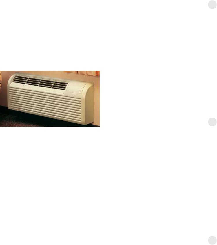
GE Zoneline® packaged terminal air conditioners
2010 contract sales architects and engineers data manual
Quick Reference
Full Specs on pages 52 and 53
ALL UNITS REQUIRE POWER CONNECTION KIT
Power Connection Kit determines resistance heat output 7000 Btuh units are not offered with 4.7 KW resistance heater
4100 Series Cooling with Electric Heat
MODEL |
COOLING |
EER |
|
NUMBER |
(Btuh) |
||
|
|||
AZ41E07DA* |
7300/7100 |
12.8/12.8 |
|
AZ41E09DA* |
9450/9250 |
12.3/12.3 |
|
AZ41E12DA* |
11800/11600 |
11.8/11.8 |
|
AZ41E15DA* |
14700/14500 |
10.6/10.6 |
|
AZ41E07EA* |
7300 |
12.8 |
|
AZ41E09EA* |
9450 |
12.3 |
|
AZ41E12EA* |
11800 |
11.8 |
|
AZ41E15EA* |
14700 |
10.6 |
Dry Air 25
4100 Series Cooling with Electric Heat
MODEL |
COOLING |
EER |
|
NUMBER |
(Btuh) |
||
|
|||
AZ41E07DAP |
6800/6600 |
12.2/12.2 |
|
AZ41E09DAP |
9000/8800 |
11.8/11.8 |
|
AZ41E12DAP |
11200/11000 |
11.3/11.3 |
|
AZ41E07EAP |
6800 |
12.2 |
|
AZ41E09EAP |
9000 |
11.8 |
|
AZ41E12EAP |
11200 |
11.3 |
6100 Series Heat Pump with Backup Electric Heat
MODEL |
COOLING |
EER |
Reverse Cycle |
COP |
|
NUMBER |
(Btuh) |
BTUH |
|||
|
|
||||
|
|
|
|
|
|
AZ61H07DA* |
7200/7000 |
13.2/13.2 |
6400/6200 |
4.0/4.0 |
|
AZ61H09DA* |
9400/9200 |
12.7/12.7 |
8300/8100 |
3.8/3.8 |
|
AZ61H12DA* |
11800/11600 |
12.1/12.1 |
10600/10400 |
3.7/3.7 |
|
AZ61H15DA* |
14800/14600 |
11.2/11.2 |
14000/13900 |
3.3/3.3 |
|
AZ61H07EA* |
7200 |
13.2 |
6400 |
4.0 |
|
AZ61H09EA* |
9400 |
12.7 |
8300 |
3.8 |
|
AZ61H12EA* |
11800 |
12.1 |
10600 |
3.7 |
|
AZ61H15EA* |
14800 |
11.2 |
14000 |
3.3 |
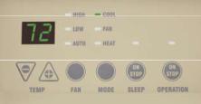
4100 and 6100 Series Control Panel
*Dual-rated 230/208-volt units are shown with ratings separated by “/”. Units with single rating are 265-volt units.
2

Power Connection Kits
230/208-Volt Line Cord Connection Units
Line Cord |
Electric |
Electric |
Electric |
Min. Circuit |
|
Heat |
Heater |
Heat |
Protection |
||
Kit |
|||||
BTUH |
Watts |
Amps |
(Amps) |
||
|
|||||
|
|
|
|
|
|
RAK3153A |
8150/7900 |
2400/2320 |
11.0/11.6 |
15 |
|
RAK3203A |
11200/10900 |
3300/3200 |
15.1/16.0 |
20 |
|
RAK3303A |
16000/15450 |
4700/4530 |
21.2/22.4 |
30 |
Electric Heat Amps include electric heater and fan motor current draw.
Each Line Cord Kit has an integral Leakage Current Detection and Interruption (LCDI) or Arc Fault Current Interrupter (AFCI) device as required by National Electrical Code (NEC) and Underwriters Laboratories (UL) for units manufactured after August 1, 2004.
geappliances.com
230/208-Volt Sub-Base and Direct Connected Units
|
Direct |
Electric |
Electric |
Electric |
Min. Circuit |
Sub-Base |
Connection |
Heat |
Heater |
Heat |
Protection |
|
Kit |
BTUH |
Watts |
Amps |
(Amps) |
|
|
|
|
|
|
RAK204D15P |
RAK4157 |
8150/7900 |
2400/2320 |
11.0/11.6 |
15 |
RAK204D20P |
RAK4207 |
11200/10900 |
3300/3200 |
15.1/16.0 |
20 |
RAK204D30P |
RAK4307 |
16000/15450 |
4700/4530 |
21.2/22.4 |
30 |
Electric Heat Amps include electric heater and fan motor current draw.
Units connected through sub-base do not require an LCDI or AFCI device since they are not considered to be line-cord connected. Each 230/208-volt sub-base kit consists of sub-base with appropriate receptacle for minimum circuit amperage, chaseway to route power connector from sub-base to chassis, wiring to connect sub-base to building wiring and a short line cord with 9-pin connector to connect to chassis and plug into receptacle in sub-base.
Short sub-base line cord may not be used without sub-base. Junction box for 230/208-volt chassis must be purchased separately.
RAK4002A for 2900, 3900, 4100, and 6100 series units, RAK4002B for 5800 series units.
265-Volt Sub-Base and Direct Connected Units
Sub-Base |
Power |
Direct |
Electric Heat |
Electric Heater |
Electric Heat |
Min. Circuit Protection |
|
Connection Kit |
Connection Kit |
BTUH |
Watts |
Amps |
(Amps) |
||
|
|||||||
RAK204E15 |
RAK5172 |
RAK5157 |
8150 |
2400 |
9.6 |
15 |
|
RAK204E20 |
RAK5202 |
RAK5207 |
11550 |
3400 |
13.3 |
20 |
|
RAK204E30 |
RAK5302 |
RAK5307 |
16350 |
4800 |
18.6 |
30 |
Electric Heat Amps include electric heater and fan motor current draw.
265-volt units are to be permanently connected in compliance with National Electrical Code and local codes and have a factory-installed junction box on the chassis. Each 265-volt sub-base kit consists of sub-base with appropriate receptacle for minimum circuit amperage, chaseway to route power connector from sub-base to chassis and wiring to connect sub-base to building wiring.
265-Volt Power Connection Kit must be ordered separately.
Important
Essential Elements Ordering Overview
230/208-volt line cord connected units — order line cord kit 230/208-volt sub-base connected units — order sub-base 265-volt units — order sub-base and power connection kit
Zoneline® Chassis Nomenclature
The Zoneline chassis is identified by a model number defining the type of unit, cooling capacity, electrical information and optional features included on the unit. When specifying or ordering the Zoneline chassis, the use of this nomenclature will assure receiving the correct unit.
|
A |
Z |
6 |
1 |
|
H |
1 |
2 |
D |
A |
D |
||||||
|
|
|
|
|
|
|
|
|
|
|
|
|
|
|
|||
|
Zoneline |
|
Chassis series |
|
|
Nominal cooling capacity |
Universal |
|
|||||||||
|
packaged |
|
41=deluxe line cool/ |
|
07=7,000 BTUH cooling |
|
power connection |
|
|||||||||
|
terminal |
|
electric heat |
|
|
|
09=9,000 BTUH cooling |
|
|
|
|
||||||
|
|
|
|
|
|
|
|
|
|||||||||
|
chassis |
|
61=deluxe line heat pump |
|
12=12,000 BTUH cooling |
|
Special Features |
|
|||||||||
|
|
|
|
|
|
|
|
|
15=15,000 BTUH cooling |
|
|
||||||
|
|
|
|
Unit type |
|
|
|
|
|
|
|
|
|
B=base unit |
|
||
|
|
|
|
|
|
|
|
|
|
|
|
|
C=corrosion treated |
||||
|
|
|
|
E=cooling with electric |
|
|
Voltage/Phase/ |
|
|||||||||
|
|
|
|
|
|
|
D=internal |
|
|||||||||
|
|
|
|
resistance heat |
|
|
Frequency |
|
|
|
|
||||||
|
|
|
|
|
|
|
|
|
|
condensate |
|
||||||
|
|
|
|
H=heat pump with electric |
|
|
D=230/208-Volt, |
|
|
|
|||||||
|
|
|
|
|
|
|
|
removal (ICR) |
|
||||||||
|
|
|
|
resistance heat |
|
|
single-phase, 60 Hz |
|
|
|
|||||||
|
|
|
|
|
|
|
|
system (heat |
|
||||||||
EXAMPLE |
|
|
|
|
|
|
|
|
|
|
|
|
|||||
|
|
|
|
|
|
|
|
|
|
|
|
|
|
|
|
|
|
|
|
|
|
|
|
|
|
|
|
|
|
|
|
|
|
|
|
|
|
|
|
E=265-Volt, single-phase, |
|
pump models |
|||||
|
|
|
|
||||||||
|
|
|
|
60 Hz |
|
||||||
|
|
|
|
|
only) (not for |
||||||
|
|
|
|
|
|
|
|
||||
|
|
|
|
|
|
|
|
coastal areas) |
|||
|
|
|
|
|
|
|
|
P=Dry Air 25 (4100 |
|||
|
|
|
|
|
|
|
|
Series only) |
|||
|
|
|
|
|
|
|
|
|
|
|
|
3
The Zoneline® 4100 and 6100 Series have incorporated changes suggested by customers, along with enhancements by GE’s Technology Team and changes necessary to meet new UL and NEC requirements.
“L” shaped condenser coil.
Cross flow blower across the product line for quieter operation.
The “Partial Open Vent Air” feature was a specific request by a customer.
“Heat Sentinel” is an enhancement developed by GE’s Technology Team to help lodging professionals welcome their guests with a moderate-temperature room and to help lower cooling costs.
Devices have been added on cord-connected units to protect against injury from unsafe power cords.
See the “Features and Benefits” section for in-depth explanation of these changes and the industry-leading features of GE Zoneline retained from the previous series.
The Deluxe 4100 Series Zoneline models include The “Dry Air 25” models which remove 25% more moisture than other Zoneline models.
Deluxe Dry Air 25 Models
Cooling With Resistance Heat
•Removes 25% more moisture than standard Zoneline models.
•Cools and dries air in less time than standard Zoneline models
•Dry Air is a separate sealed refrigerant system
—No mechanical parts — No special maintenance required
•Helps maintain lower relative humidity in rooms
•Maintains comfort at slightly higher room temperatures
—Reduces operating costs — Provides comfort without overcooling
•Corrosion treatment is standard
•Excellent choice for humid climates
•Available in 7000, 9000 and 12000 BTU sizes
The Dry Air 25 system, a heat pipe, is a hermetically sealed heat transfer surface installed in a “saddlebag” configuration around the indoor (evaporator) coil of the Zoneline unit. This coil arrangement will transfer heat from the front coil of the saddlebag to the rear coil without power consumption.
This assembly uses R-410A as the refrigerant and is not connected to the regular Zoneline refrigerant circuit.
As warm, humid air is pulled through the pre-cool (front) section of the heat pipe, the heat removed from the air is absorbed by the refrigerant, causing the refrigerant to change to a gas and flow to the re-heat (rear) section of the heat pipe. The air leaving the pre-cool section of the heat pipe is cooler and at a higher relative humidity level than the room air. The pre-cooled air is further cooled as it passes through the evaporator; consequently allowing the evaporator coil to remove more moisture.
When the cold air from the evaporator comes in contact with the re-heat section of the heat pipe, the heat that was removed by the pre-cool section is added back to the air and the refrigerant in the heat pipe condenses and flows back to the pre-cool (front) section. The air discharged into the room by this process is much drier, creating a more comfortable room condition.
The Dry Air 25 models center around GE’s exclusive use of the patented Dinh® Dehumidifier Heat Pipe from Heat Pipe Technology, Inc. This innovative NASA spin-off technology enables Dry Air 25 to remove 25% more moisture from the air than other leading manufacturers’ packaged terminal air conditioners. This helps maintain room comfort at a higher room temperature, reducing operating costs.
The Dry Air 25 keeps a room cool and dry, and this is the most important benefit when it comes to the occupant of the room—hotel guests, apartment residents, students. In a hot, humid climate, getting away from the humidity is just as important as getting away from the heat, and the Dry Air 25 is the perfect solution. The dehumidification of the Dry Air 25 has been verified by the same ARI test conditions that standard units are rated under.
4

Table of Contents
Front Cover |
1 |
Mini Specs 4100 and 6100 Series |
2 |
Mini Specs Power Connection Kits and Nomenclature |
3 |
The 4100/6100 and Dry 25 |
4 |
Table of Contents |
5 |
Introduction |
6 |
The Zoneline System |
7 |
Features and Benefits |
|
Features Table |
8 |
Features and Benefits |
9–11 |
Auxiliary Control Settings |
12–13 |
Central Desk Control |
14 |
Remote Thermostat Control |
15–17 |
Heat Pumps and Energy Savings |
18–19 |
Installation and Dimensions |
|
Application Comments |
20 |
Case Dimensions |
21 |
Wall Case/Sub-Base Installation |
22–33 |
Condensate Disposal Systems |
34–36 |
Ducted Installations |
37–39 |
Exterior Grilles |
40–41 |
Product Data |
|
Electrical Connection |
42 |
Essential Elements Ordering Overview |
43 |
Maximum Connected Load |
44 |
Latent System Capacity |
44 |
Normal Yearly Operating Data |
45 |
Schematics |
46–49 |
Product Specifications |
|
Suggested Bid Form Specifications |
50–51 |
Zoneline Chassis Nomenclature/Receptacles/Sub-Bases |
52 |
Installation Specifications |
53 |
Complete Accessory List |
54 |
General Installation Suggestions |
55–56 |
Warranty |
56 |
Notes |
57-58 |
Alphabetical Index |
59 |
Back Cover |
60 |
geappliances.com
Important Notice
Equipment used as a primary source for heating or cooling is an integral part of the building in which it is installed. Proper application is essential for satisfactory performance over a wide range of operating conditions. It is strongly recommended that a professional engineer determine proper application.
If the unit is a replacement unit, its specifications and performance may differ from those of the unit it is replacing. For that reason, we again
strongly recommend that a professional engineer determine proper application.
5

Introduction
This manual is designed to provide product, performance and application information to our customers and their architects and engineers for use in selection and design of a zonal comfort control system utilizing GE Zoneline® Packaged Terminal Air Conditioners (PTAC) and Packaged Terminal Heat Pumps (PTHP). GE Zoneline PTACs and PTHPs are self-contained units designed for through-the-wall installations in hotels, motels, apartments, hospitals,
nursing homes, add-on rooms and many other installations.
Zoneline units provide individual room or zone control in both cooling and heating operation. There is a model for practically every application, ranging in cooling capacity from 7,200 to 14,800 BTUH and heating capacity from 6,400 to 14,000 BTUH in heat pump operation. See pages 42 and 54 for resistance heaters available.
Zoneline offers a two-tier lineup: The Deluxe Line consists of the 4100 Series with electric resistance heat, the 4100 Series Dry Air 25 Models with enhanced dehumidification for hot and humid climates and the 6100 Series heat pump. The 6100 Series heat pump features reverse cycle defrost and simultaneous supplemental resistance heat, when needed, to maintain room comfort. Both offer tactile touch controls with digital display and optional corrosion protection.
Deluxe Line Standard Features:
•Two-fan-motor system with Indoor Cross-Flow
Blower for quieter operation
•Digital Controls
— LED Temperature Display
— Easy Temperature Selection
— Tactile Touch Pad
•Universal Heaters
•Heat Sentinel
•“L” Coil Design Condenser
•3-Position Vent Door
•Freeze Sentinel™
•Indoor Coil Frost Control
•Central Desk Control Interface
•Remote Thermostat Control Interface
•Random Restart
•Electronic Temperature Limiting
•“Smart Fan” Fan Cycle/Continuous Control
•Transfer Fan Interface
•Reverse Cycle Defrost and Simultaneous
Supplemental Resistance Heat on Heat Pumps
•Quick Heat Recovery
Deluxe Line Optional Features:
•Corrosion Protection
•Internal Condensate Removal (on 6100 Series
Heat Pump without Corrosion Protection)
NOTE: Dry Air 25 models include all the standard features of the 4100 Series plus standard corrosion protection.
Advantages of the GE Zoneline System:
•Flexible Application
— May be installed from flush to finished floor to 3" from the ceiling
— 7,200 to 14,800 BTUH units in same physical size
— Deluxe 4100 and 6100 Series may be ducted to condition more than one room
— Compatible with Class 2 remote thermostat control
— Compatible with 2-wire CDC or many Energy Management Systems
•Economical Installation
— No ductwork necessary
— No mechanical equipment rooms or pipes required for heating/cooling units
— Replacement units fit existing 42"-wide by 16"-high wall cases
•Quiet Operation
— Indoor cross-flow blower
•Energy-Saving Operation
— Units in unoccupied areas may be turned off
— Designed for efficient cooling operation — EERs from 10.6 to 13.2
— Efficient heat pump units — COPs from 3.3 to 4.0
—Extended heat pump operation without sacrificing room comfort
•Ease of Maintenance
— Permanently lubricated fan motors
— Upfront lift-out interchangeable filters
— Slide-out chassis for easy access for cleaning or if service is required
•Reverse Cycle Heat Pump Operation
The 6100 Series heat pumps utilize the unique GE PTAC heat pump operation to ensure a comfortable room. The logic used by the units is the same logic used by central system heat pumps to provide greater savings.
6
geappliances.com
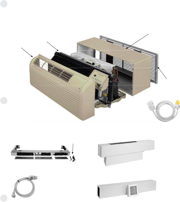
The Zoneline System
The typical Zoneline installation consists of the wall case (or sleeve), chassis, power cord and exterior grille. Some installations may use a sub-base for support of the unit or for ease of electrical connections. Each of the components should be the standard products offered by GE or, in the case of the exterior grille, approved by GE Applications Engineering. Use of components not specifically designed or approved for use with the Zoneline unit can result in unsatisfactory operation
and can be the cause of failure not covered by the warranty.
Components of the Zoneline System Typical Installation (Deluxe Series shown)
Chassis
Room Cabinet
Optional Accessories of the Zoneline System
Chaseway
RAK204D20P Sub-Base (shown)
Power Supply Cord (included with 208V/230V sub-bases)
See pages 22 and 32 for information on electrical sub-bases and chaseway. See pages 37-39 for information on ducted installations.
Wall Case
RAB71A (Steel-Insulated) RAB77A4 (SMC — Molded) Wall Case Options
(See page 22)
RAG67 (shown) Grille Options (See page 40)
Power Connection Kit (required on all units)
Line Cord Kit shown
See pages 42-43
Power Supply Cord
RAK6052 Duct Adapter
RAK601/602
Duct Extension, Register and Trim Flange
7

Zoneline® Features
|
Resistance heat |
Heat pump |
||
|
AZ |
AZ |
AZ |
|
|
41 Series |
41 Dry Air 25 |
61 Series |
|
Cooling EER Range (230 Volts/265 Volts) |
10.6 - 12.8 |
11.3 - 12.2 |
11.2 - 13.2 |
|
|
|
|
|
|
Heating COP Range (230 Volts/265 Volts) |
N/A |
N/A |
3.3 - 4.0 |
|
Refrigerant type |
R-410A |
R-410A |
R-410A |
|
|
|
|
|
|
Cross-flow (tangential) blower |
Standard |
Standard |
Standard |
|
|
|
|
|
|
Enhanced Dehumidification |
Optional |
Standard |
— |
|
|
|
|
|
|
Heat pump with resistance heat back-up |
— |
— |
Standard |
|
|
|
|
|
|
Heat pump with supplemental resistance heat |
— |
— |
Standard |
|
Staged Heating |
— |
— |
3-Stage*** |
|
|
|
|
|
|
Universal heaters - UPC** |
Standard |
Standard |
Standard |
|
|
|
|
|
|
Tactile touch pad controls with LED |
Standard |
Standard |
Standard |
|
|
|
|
|
|
Touch control set-up features |
Standard |
Standard |
Standard |
|
|
|
|
|
|
Highly featured microcomputer controls |
Standard |
Standard |
Standard |
|
Electric resistance heat lock-out (above 46°F) |
— |
— |
Standard |
|
|
|
|
|
|
Automatic emergency heat |
Standard |
Standard |
Standard |
|
|
|
|
|
|
Heat pump defrost system |
— |
— |
Reverse cycle |
|
|
|
|
|
|
High-Temperature Operation Protection |
— |
— |
Standard |
|
|
|
|
|
|
Quick heat recovery |
— |
— |
Standard |
|
|
|
|
|
|
Temperature Boost |
— |
— |
Selectable |
|
Separate Indoor & Outdoor |
AC |
AC |
DC |
|
Motors — Permanently Lubricated |
||||
|
|
|
||
|
|
|
|
|
2-Speed Outdoor Fan |
Standard |
Standard |
Standard |
|
|
|
|
|
|
Indoor fan speed settings |
Hi/Low |
Hi/Low |
Hi/Low |
|
Fan Only setting—2-speed |
Hi/Low |
Hi/Low |
Hi/Low |
|
Cool & heat only settings |
Hi/Low/Auto |
Hi/Low/Auto |
Hi/Low/Auto |
|
|
|
|
|
|
“SmartFan” Fan Cycle Control |
Standard |
Standard |
Standard |
|
|
|
|
|
|
Auto power recovery |
Standard |
Standard |
Standard |
|
|
|
|
|
|
Automatic Compressor Restart Delay |
Standard |
Standard |
Standard |
|
|
|
|
|
|
Freeze Sentinel™ (41F) |
Standard |
Standard |
Standard |
|
Heat Sentinel (85F) |
Standard |
Standard |
Standard |
|
|
|
|
|
|
Automatic indoor frost control |
Standard |
Standard |
Standard |
|
|
|
|
|
|
Temperature limiting |
Electronic 7-step |
Electronic 7-step |
Electronic 7-step |
|
|
|
|
|
|
Solid-state thermostat |
Standard |
Standard |
Standard |
|
|
|
|
|
|
Remote thermostat compatibility |
Standard |
Standard |
Standard |
|
Central desk control compatibility |
Standard |
Standard |
Standard |
|
|
|
|
|
|
2-position discharge grille 50º/40º |
Standard |
Standard |
Standard |
|
|
|
|
|
|
Upfront filter (interchangeable) |
Standard |
Standard |
Standard |
|
|
|
|
|
|
3-position manual air vent control |
Standard |
Standard |
Standard |
|
|
|
|
|
|
Sleep function |
Standard |
Standard |
Standard |
|
|
|
|
|
|
Transfer Fan Connections |
Standard |
Standard |
Standard |
|
Ducted Installation Capability |
Optional |
Optional |
Optional |
|
|
|
|
|
|
Corrosion-treated chassis |
Optional |
Standard |
Optional |
|
|
|
|
|
|
Internal condensate removal (ICR)* |
— |
— |
Optional |
|
|
|
|
|
|
*Not for use in corrosive environments |
|
|
|
|
**UPC — Universal Power Cord Connection (see pages 42 and 54).
*** Two stage heating if using remote thermostat
265-volt units must be connected in a manner to meet National Electrical Code and all local codes.
8

Features and Benefits
Standard Physical Dimensions
GE has maintained the same dimensions since 1961 — 42" wide x 16" high x 13-3/4" deep
Replacement of older units is made easy.
Weather-Protected Electrical Components
Vital electrical components are protected from the weather by locating them on the indoor side of the weather barrier.
Weather-Resistant “Superseal”
Properly installed unit in undistorted case keeps air leakage to a minimum.
7 CFM air infiltration with 25 MPH wind on ICR units — even less on units without ICR.
Industry specification is 19 CFM of air infiltration.
Heater Sizes to Meet Room Requirements
All units are equipped with a universal heater — the resistance heat output is determined by power connection kit.
230/208-volt — Line-Cord Connected Units — 2.4/2.32 KW with RAK3153A — 15-amp circuit; 3.3/3.20 KW with RAK3203A — 20-amp circuit; 4.7/4.53 KW with RAK3303A — 30-amp circuit.
230/208-volt - Sub-Base Connected Units — 2.4/2.32 KW with RAK204D15P — 15-amp circuit; 3.3/3.20 KW with RAK204D20P — 20-amp circuit; 4.7/4.53 KW with RAK204D30P
— 30-amp circuit.
265-volt — 2.4 KW with RAK5172 — 15-amp circuit; 3.4 KW with RAK5202 — 20-amp circuit; 4.8 KW with RAK5302 — 30-amp circuit.
Unit Controls
4100 and 6100 Series — touch pad controls with digital readout of temperature set point.
Highly Featured Microprocessor Controls
Microprocessor controls are programmed to interface with the temperature sensors to maximize comfort conditions for the room occupant and provide outstanding features.
Thermistors are used to sense small changes in temperature to give excellent room control and allow the microprocessor to monitor and react to changing conditions.
Electric Resistance Heat Lock-Out
To maximize the savings of the heat pump operation, the Zoneline heat pumps do not utilize the resistance heater when the outdoor temperature is above 46°F during normal operation. The resistance heat is used in the Quick Heat
Recovery feature.
geappliances.com
Automatic Emergency Heat
Automatically uses electric resistance heat if the heat pump output is not sufficient to maintain selected room temperature.
Reverse Cycle Heat Pump Defrost System
Standard on all Zoneline 6100 Series heat pumps.
Enables heat pump to operate at lower temperatures when other systems switch to more expensive electric resistance heat.
See pages 18 and 19 for discussion of heat pump operation and defrost systems.
High-Temperature Heat Pump Operation Protection
Automatically protects the compressor if heat pump is operated with high outdoor temperatures.
Power to the outdoor fan is turned off if the indoor coil gets too hot during heat pump operation to prevent damage to the compressor.
Quick Heat Recovery – Heat Pump Units
When the unit operation is changed from STOP or COOL to HEAT, the electric resistance heaters are used to warm the room to the thermostat set point. This provides faster room temperature increase for greater guest comfort.
Fan Motors – Permanently Lubricated
All units have two fan motors for quiet operation and maximum operating efficiency.
Motors are permanently lubricated to reduce maintenance and totally enclosed to keep dirt and water out of the motor windings.
Outdoor Fan
The unit automatically selects the most efficient speed for the outdoor fan. The operating sound level is lower when the outdoor fan can operate in low speed yet there are situations where it must operate in high speed. The unit changes the fan speed automatically.
Indoor Fan Speed Selections – HIGH/LOW
Unit may be operated in HIGH HEAT or LOW HEAT or HIGH COOL or LOW COOL.
9
Features and Benefits
Fan-Only Setting – HIGH/LOW
The unit provides the option of selecting either HIGH or LOW speed for Fan-Only operation.
Fan-Cycle Switch – “SmartFan”
Unique “SmartFan” allows unit to operate fan continuously
in cooling operation and fan cycle in heating to provide better guest comfort. Eliminates complaint of cold air draft during heating operation.
Eliminates need of changing fan-cycle switch seasonally.
“SmartFan” settings are controlled via the auxiliary control setting push button.
Compressor Random Restart
In the event of a power failure, all compressors attempting to restart immediately when power is restored can result
in a power surge that can cause another power interruption.
The microprocessors in the Zoneline® units have a random restart logic system that prevents all units from starting at the same time.
Rotary Compressor
Smoother operation for quiet, dependable service. GE has used rotary compressors since 1961.
Compressor Restart Delay
Zoneline units are designed to provide a minimum of three minutes of compressor off time to allow refrigerant pressures to equalize before restarting to prevent compressor damage.
Zoneline units are also designed to provide a minimum of three minutes of compressor run time to prevent room occupant disturbance due to short-cycling of the air conditioner.
Freeze Sentinel™
Detects low room temperature and turns on heater to help protect against damage caused by freezing room temperature.
Heater turns on at 41°F and warms indoor thermistor temperature to 46°F and shuts off.
Freeze Sentinel may be turned off by dip switch on auxiliary control.
Heat Sentinel
The property owner may choose to activate the Heat Sentinel feature on the Zoneline unit. If the Heat Sentinel is activated and room temperature reaches 85°F while the
unit is in the “STOP” setting, the unit will automatically start in air conditioning operation and will shut off when the room temperature reaches 80°F. This will help dehumidify the air and lower high temperatures so the guest will not be entering an extremely hot room.
Indoor Coil Frost Control
Prevents indoor coil from freezing and causing complaints due to lack of cooling. Frost can form on the indoor coil when the unit is operated in cooling when outdoor temperatures are low. The unit automatically shuts
the compressor off until the indoor coil temperature warms to the point where frosting will no longer occur.
Transfer Fan Interface
24 VAC terminals are provided to operate a relay to control a fan mounted in a wall to move conditioned air into another space. The electrical power for the operation of the transfer fan itself is not provided by the Zoneline unit. Transfer fans and their controlling relays are field supplied.
Electronic Temperature Limiting
Seven independent programmable heating temperature limits and seven independent programmable cooling temperature limits.
|
Heating Temperature Limits |
|
Highest |
||||
|
|
Heat |
|||||
|
|
|
|
|
|
|
|
|
|
|
|
|
|
|
|
65 |
70 |
72 |
74 |
76 |
78 |
80 |
85 |
|
|
|
|
|
|
|
|
Lowest |
|
Cooling Temperature Limits |
|
||||
Cool |
|
|
|||||
|
|
|
|
|
|
|
|
|
|
|
|
|
|
|
|
60 |
64 |
66 |
68 |
70 |
72 |
74 |
76 |
|
|
|
|
|
|
|
|
Limits are set via the auxiliary control setting push button.
Remote Control Capability with Wall-Mounted Thermostat
See pages 15–17.
Central Desk Control Capability
See page 14.
Energy Management System Interface with Load-Shedding Option
All units have a switch via the auxiliary control setting to allow the indoor fan to continue operating if the unit is connected to an energy management system that shuts off compressor or heater operation. By allowing the indoor fan to run when the heater or compressor is shut off by the energy management system, the guest is less likely to realize the operation of the unit has been altered. This helps reduce peak energy demand loads without disturbing the room occupant.
Reversible Indoor Air Louvers
Allows air to be directed into room at 40º or 50º angle to provide better air distribution.
Angle is changed by removing room front and screws holding louver in place, and rotating louver section.
10
Features and Benefits
Up-Front Air Filters
Two interchangeable up-front filters, easy
to remove and reinstall, may be cleaned without opening or removing the room front.
Clean filters by brushing, vacuuming or backflushing under faucet or shower head.
Concealed Manual Vent Control
Open ventilation doors on GE Zoneline® Packaged Terminal Air Conditioners and Heat Pumps allow
outside air to enter the room through a screen-covered opening in the weather barrier that separates the indoor and outdoor sections of the unit.
A concealed lever is located along the left side of the unit under the front cover is used to open and close the vent door.
The 3-position manual vent door control may be closed, partially open or fully open. Positive vent door closure prevents accidental opening and unwanted air infiltration.
Vent CFM High Speed
Unit |
Full Open |
Partial Open |
7000 |
50 |
40 |
9000 |
70 |
45 |
12000 |
75 |
45 |
15000 |
75 |
45 |
CFM ratings at 230 and 265 volts.
For each CFM of air to enter the room, an equal amount of air must be removed through exhaust fans in the bathroom or roof tops. Greater amounts of air will be introduced (from chart shown above) depending on the size of the exhaust fan.
Outside ambient air entering the room through this screened vent opening is not conditioned. This unconditioned air becomes mixed with the conditioned air that is circulated by the indoor fan. This air mixture generates an additional heat load/heat loss that causes the unit to run longer and may translate into higher operating costs.
Zoneline vent openings are not intended to be the source of make-up air for building ventilation systems due to the additional heating or cooling loads generated.
geappliances.com
Corrosion Protection (Optional)
4100 and 6100 Series units may be ordered with special protection to better withstand damage from salt air and salt water in seacoast areas.
Corrosion protection is standard on the Dry Air 25 models.
Heat pump units with ICR are not available with corrosion protection and should not be installed in seacoast or corrosive environments.
Units installed in corrosive areas should use the RAB77 wall sleeve and be examined/cleaned more frequently than normal installations.
Internal Condensate Removal (ICR)
See page 34 for a discussion of the Internal Condensate Removal system available on 6100 Series heat pumps.
Enhanced Dehumidification
Moisture removal is an important function of an air conditioner. People are more comfortable at higher temperatures when the humidity level is relatively low. Air conditioners operate with less energy consumption when the room temperatures are set higher.
The GE Zoneline 4100 Series with the Dry Air 25 heat pipe application removes 25% more moisture than the base 4100 Series unit.
The GE Zoneline Dry Air 25 chassis is the only PTAC available with the application of the patented Dinh® Dehumidifier Heat Pipe under license from Heat Pipe Technology, Inc.
Customers who are using the Dry Air 25 report a freshersmelling room as a result of the lower humidity levels, as well as lower operating costs.
Locking Door Kit
RAK8023 — A door with a lock that replaces the standard control cover door to prevent unauthorized changing of control setting is offered as an accessory.
11

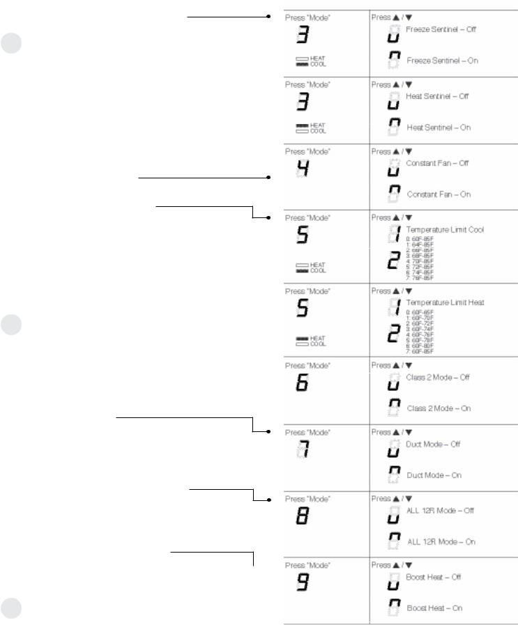
Auxiliary Control—Aux Set Button
The auxiliary control push button is located behind the room cabinet, below the control panel. The auxiliary controls come preset to the modes most desired by customers. However, the owner is responsible for ensuring the auxiliary controls are set to the desired function. There are 9 different modes that can be set using the auxiliary set button.
To change modes:
•Press AUX SET (“AU” appears on the display).
•Press the MODE button on the control pad until the first digit in the display shows the number corresponding to the mode you are choosing and the correct HEAT/COOL LED is lit.
•Press the up or down arrow to change the mode setting selection (second digit in the display).
•Press the MODE button to move to the next feature or the AUX SET button to exit the set up process.
Auxiliary Set Button
Access
Cover
Auxiliary Control Settings
Mode 1—Smart Fan—Cooling/Heating  The default setting for Mode 1 is as follows:
Cooling: Continuous (ON) Heating: Cycle (OFF)
Mode 2—Load Shedding (Central Desk Control)  The default setting for Mode 2 is OFF.
This feature is active only if the unit is connected to a CDC and the CDC has control. When this mode is on, only the indoor fan can be turned ON or OFF with the unit controls. When this mode is off, all operation is disabled except Heat/Freeze Sentinel (Mode 3).
12
Auxiliary Control Settings (cont)
Mode 3—Freeze Sentinel/Heat Sentinel The default settings for Mode 3 are:
Heat Sentinel is off Freeze Sentinel is on.
When Freeze Sentinel is activated, it automatically provides heat without user interface. This helps to prevent plumbing damage by turning the heater and indoor fan ON at 41ºF and OFF at 46ºF.
When Heat Sentinel is activated, it automatically provides cooling without user interface. This helps to prevent an excessively hot room by turning the air conditioner ON at 85ºF and OFF at 80ºF.
NOTE: These functions are active whenever the unit is plugged in, even if the unit is in the STOP position.
Mode 4—Constant ON Fan
The default setting for Mode 4 is OFF.
Mode 5—Temperature Limiting
The default setting for Mode 5 is as follows: Cool: 0 (60ºF to 85ºF)
Heat: 7 (60ºF to 85ºF)
Temperature limits—Cool |
Temperature limits—Heat |
||
0 |
= 60°F to 85°F |
0 |
= 60°F to 65°F |
1 |
= 64°F to 85°F |
1 |
= 60°F to 70°F |
2 |
= 66°F to 85°F |
2 |
= 60°F to 72°F |
3 |
= 68°F to 85°F |
3 |
= 60°F to 74°F |
4 |
= 70°F to 85°F |
4 |
= 60°F to 76°F |
5 |
= 72°F to 85°F |
5 |
= 60°F to 78°F |
6 |
= 74°F to 85°F |
6 |
= 60°F to 80°F |
7 |
= 76°F to 85°F |
7 |
= 60°F to 85°F |
Mode 6—Remote Thermostat – Class 2  The default setting for Mode 6 is OFF.
Setting this mode to ON will allow the unit to operate with a Class 2 Remote Control Wall Thermostat.
Mode 7—Duct Mode
The default setting for Mode 7 is OFF.
This setting is used when the unit is installed using a duct adapter kit. If the unit is ducted, the Duct Mode needs to be set to ON. This increases the fan speed to ensure proper circulation.
Mode 8—All-Electric Heat (AZ6100 only) The default setting for Mode 8 is OFF.
This electric heat option functions only on the 6100 model. When this option is ON, heat pump operation is locked out, causing the unit to provide only electric resistance heat.
Mode 9—Heat Boost (AZ6100 only)
The default setting for Mode 9 is OFF.  When Heat Boost is ON and outer temperatures are between 25ºF and 46ºF, heat pump only operation is locked out. This setting is used to provide supplementary heat to the heat pump operation by electric resistance heat in conditions where the heat pump-only operation is not sufficient to maintain a consistent, comfortable room temperature. NOTE:
Temperature Boost option should not be used with remote thermostat operation. This will cause the unit to switch to resistance heat when the outdoor temperature is 46ºF.
geappliances.com
13
Central Desk Control
Some installations may want to govern the ability of the unit to operate from a control device remote to the unit or even remote to the room in which the unit is located. The general term given to systems such as this is Central Desk Control. The most common installation of this type of system is a switch mounted at the registration desk and, upon guest check-in, a button is pushed or a switch is moved to allow the air conditioner to operate. Likewise, when the guest checks out the device is put into the “OFF” position so the unit will not operate while the room is vacant.
It is not necessary that the controlling device be located at a central desk to employ a device that will control the unit operation. For instance, in some resort areas devices are connected to sliding glass doors and opening the door causes a contact to close, turning the air conditioner off. This prevents energy being wasted by operating the air conditioner when warm, humid air is entering the room. Some systems operate by motion sensors or heat-sensing detectors mounted in the room. These types of systems determine occupant presence in the room and allow the unit to operate; if no one is in the room the device signals the air conditioner to turn off.
Zoneline® models offer load-shedding capabilities on units connected to Central Desk Control systems. For more information on the models’ load-shedding feature, see page 10.
There is a wide variety of devices available, each with its own benefits and constraints. While GE does not offer
components that are external to the unit for a Central Desk Control (CDC) system, GE Zoneline units are compatible with most CDC and energy management systems. Zoneline units provide a 24 VAC circuit that powers the Central Desk Control system and no external power is needed.
All Zoneline 4100 and 6100 Series units are compatible with simple on/off 2-wire Central Desk Control systems. Consult with the provider of the energy management system to be sure it is compatible with GE Zoneline units. Zoneline units have standard connectors factory-installed to provide a CDC interface that permits the unit to be connected to most of the energy management systems. The devices connected
to the Zoneline units require no power supply or transformers external to the unit.
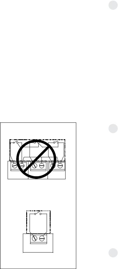
Important CDC Comments (all series applicable)
1.When the switching device closes the circuit of the CDC conductors, the unit operation stops.
2.Do not use a common bus (at the unit or at the switch panel) in the wiring. Both wires comprising the circuit must connect to the unit connectors and to the controlling switch. Running one wire from one unit to another unit is common busing and may damage internal components or cause erratic operation of the system.
3.A 24-volt transformer is contained within the Zoneline unit. No external voltage may be applied to the unit through the CDC terminals. (Voltage on the CDC conductors is
24 volts AC.)
4.Recommended wire size must be followed as a minimum requirement.
Wire Size #AWG |
Maximum Allowable Length |
|
#22 |
600 |
Ft. |
#20 |
900 |
Ft. |
#18 |
1500 |
Ft. |
#16 |
2000 |
Ft. |
Freeze Sentinel™ and Heat Sentinel remains operational when the unit is connected to a CDC system. Even if the unit is turned “OFF” at the central location, if the sensor at the unit detects the low or high limit temperature, the unit will automatically turn on until it reaches the preset shutdown temperature (46°F heating, 80°F cooling).
Connecting the Zoneline unit to a CDC system does not eliminate the ability to connect the unit to a remote thermostat. Once the circuit is “opened,” and control of the unit removed from the CDC system, the selected controls—either the unit— mounted control or the remote thermostat—govern the operation of the unit.
Please see page 55 for installation recommendations for the Central Desk Control wiring.
CDC Terminal Location and Typical Wiring
See page 15 for location of CDC terminals on unit.
Example of Common Busing |
||
|
NOT PERMITTED |
|
Unit #1 |
Unit #2 |
Unit #3 |
INCORRECT Common Busing |
||
|
Normally Open |
|
|
Switch - |
|
Unit Operational |
||
|
CDC Terminals |
|
|
on Zoneline unit |
|
|
Typical Wiring |
|
(All Wiring Shown Is Field Supplied) |
||
14
geappliances.com
Remote Thermostat Control
In some installations, control of the operation of the unit at a location remote from the unit itself may be desired. A unit mounted high in the wall or over a door, for instance, where
the unit-mounted controls are inaccessible, can be connected to a wall-mounted thermostat. Other installations may use remote thermostat control for design or performance enhancement. The unit is connected to the thermostat by low-voltage wiring which permits the operation of the unit to be selected and the temperature sensed at the thermostat.
Important Notes: Remote thermostat wiring should not be run through wall case. Thermostat wiring should exit the wall below the unit and enter the unit between room cabinet and chassis. Wire molding may be used to hide thermostat wiring. If a sub-base is used, the thermostat wiring may be concealed by the sub-base. Thermostat wiring should not be run parallel to line voltage wires since induced current may cause erratic operation.
All Zoneline 4100 and 6100 Series units are adaptable to Class 2 remote low-voltage thermostat. The only additional fieldsupplied components are the remote thermostat and wiring necessary to connect it.
The controls on the unit are not functional when the remote control function is used.
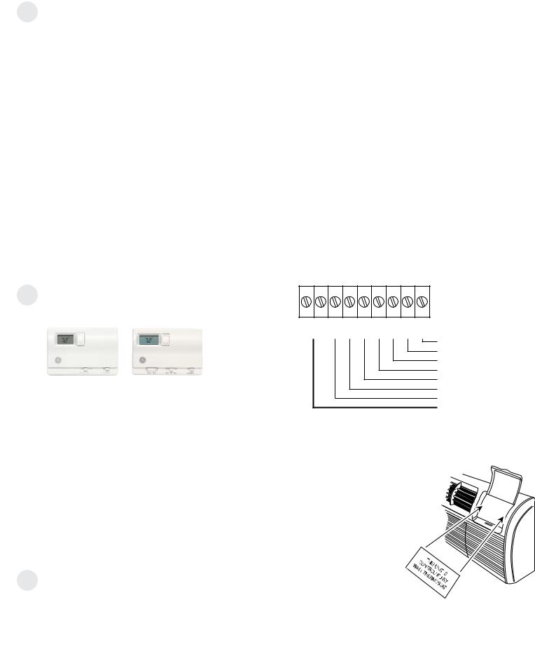
Resistance Heat Models
The Zoneline 4100 resistance heat units may be connected to a single-stage thermostat designed for use with cooling with electric heat systems. GE offers two thermostats compatible with the 4100 Series unit.
RAK164D1 — |
RAK164P1 — |
a solid-state |
a solid-state digital |
digital thermostat |
programmable |
requiring five |
thermostat |
connection wires. |
requiring five |
|
connection wires. |
The remote thermostat-Class 2 option (Mode 6 in the auxiliary control setting) must be turned ON to enable remote thermostat control. Refer to installation instructions packaged with the chassis.
Please see page 55 for installation recommendations for the remote thermostat wiring.
Compatibility of other thermostats considered for use with GE Zoneline units is the responsibility of the customer. The control voltage on the remote control conductors is 24 volts AC. The AC voltage may not be compatible with some solid-state thermostats.
The fan speed for the 4100 Series in remote thermostat operation is selected by the connection of the fan wire from the thermostat to either the HIGH or LOW terminal on the unit. See the sketch of the unit terminals below for the location of the HIGH and LOW fan-speed terminals. Operating the unit in low fan speed reduces the operating sound level of the unit.
Freeze Sentinel™ and Heat Sentinal remain operational if the unit is connected to a remote thermostat. The unit may be connected to a Central Desk Control (CDC) system and controlled with a remote thermostat when the CDC system has the unit in operation. See page 14 for additional information on the CDC system.
Unit temperature limiting settings are not functional when unit is connected to a remote thermostat.
Field Wiring Terminal
R — 24V AC
GL — Low-Speed Fan
GH — High-Speed Fan
B— Not Used on 4100
Y— Compressor
W— Heater
C— Common
RAK806 Universal Control Cover Label
CDC |
R GL GH B Y W C |
Common
White — Heater
Yellow — Compressor
Black — Not Used On 4100
Green — High-Speed Fan
Green — Low-Speed Fan
Red — 24VAC
CDC Terminal
When a Zoneline unit is using a remote thermostat control, the RAK806 Universal
Control Cover Label is recommended. The
RAK806 is only available in a
package of 10 labels. The label is placed
over the control panel to direct the user to
the wall thermostat for operation of the Zoneline unit.
15
Remote Thermostat Control
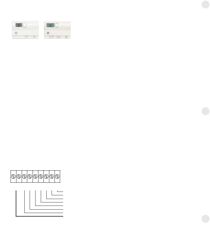
Heat Pump Models
The Zoneline® 6100 Series heat pump units may be connected to a single-stage cooling/two-stage heating thermostat designed for use with heat pump systems. GE offers two thermostats compatible with the
6100 series units:
RAK148D1 — |
RAK148P1 — |
solid-state digital |
solid-state digital |
thermostat |
programmable |
requiring six |
thermostat |
connection wires. |
requiring six |
|
connection wires. |
Please see page 55 for installation recommendations for the remote thermostat wiring. Compatibility of other thermostats considered for use with the GE Zoneline unit is the responsibility of the customer.
The control voltage on the remote control conductors is 24 VAC.
The remote thermostat-Class 2 option (Mode 6 in the auxiliary control setting) must be turned ON to enable remote thermostat control. Refer to installation instructions packaged with the chassis.
The fan speed for the 6100 Series in remote thermostat operation is selected by the connection of the fan wire from the thermostat to either the HIGH or LOW terminal on the unit. See the sketch of the unit terminals for the location of the HIGH and LOW fan speed terminals. Operating the unit in low fan speed reduces the operating sound level of the unit.
Field Wiring Terminal
R |
— 24V AC |
GL |
— Low-Speed Fan |
GH |
— High-Speed Fan |
B |
— Reversing Valve |
Y |
— Compressor |
W |
— Heater |
C |
— Common |
|
|
Feature |
Heat Pump |
Electric Heat |
Indoor Frost Control |
Yes |
Yes |
Freeze Sentinel™ |
Yes |
Yes |
Heat Sentinel |
Yes |
Yes |
Auto Fan Speed |
No |
No |
Electronic |
|
|
Temperature Limiting |
No |
No |
Switch to Resistance |
|
|
Heat Based on Indoor |
Determined by |
|
Temperature |
Remote Thermostat |
N/A |
Switch to Resistance |
|
|
Heat Based on |
|
|
Outdoor Temperature |
Yes |
N/A |
Reverse Cycle Defrost |
Yes |
N/A |
Simultaneous |
|
|
Resistance Heat |
|
|
with Heat Pump |
No |
N/A |
Resistance Heat |
|
|
Lockout |
Yes |
N/A |
“Smart Fan” |
Fan ON/AUTO Set On |
Fan ON/AUTO Set On |
Fan Cycle |
Remote Thermostat |
Remote Thermostat |
Central Desk Control |
Yes |
Yes |
When connected to a remote thermostat, the indoor-air- temperature sensing is shifted from the unit to the remote thermostat. For this reason, the units will operate slightly differently when connected to a remote thermostat. The above chart shows the unit operation when connected to a remote thermostat.
Boost heat option should not be used with remote thermostat operation since this will cause the unit to switch to resistance heat when outdoor temperatures are below 46ºF.
CDC |
R GL GH B Y W C |
Common
White — Heater
Yellow — Compressor
Black — Reversing Valve
Green — High-Speed Fan
Green — Low-Speed Fan
Red — 24VAC
CDC Terminal
16

geappliances.com
Remote Thermostat Control Selection Chart For Zoneline Packaged Terminal Units
Zoneline Series |
Thermostat Model |
Type |
Function |
Low-Voltage Conductors |
|
|
|
|
|
4100 |
RAK164D1 |
Digital |
Cooling and Heating |
5 |
|
|
|
|
|
|
RAK164P1 |
Digital Programmable |
5 |
|
|
|
|||
|
|
|
|
|
6100 |
RAK148D1 |
Digital |
Single-Stage Cooling – |
6 |
|
RAK148P1 |
Digital Programmable |
2-Stage Heating |
6 |
|
|
|
|
|
Thermostat wire size – up to 60 feet AWG20 – up to 66 feet AWG18
For remote thermostat operation follow the steps below:
1.Turn on the unit and ensure it is working properly BEFORE proceeding.
2.Unplug the unit or disconnect power and remove the room cover.
3.Connect the thermostat wiring per the appropriate diagram/colors for your model.
4.Plug the unit back in or reconnect power.
5.Press the Aux Set button once. The letters AU will appear in the display.
6.Press the mode button until the number “6” appears in the left hand digit.
7.Press the up arrow once so the top half of the right hand digit is lit.
8.Press the Aux Set button to exit the setup function.
9.Replace the room cover.
See pages 12 and 13 for full instructions on using the
Auxiliary Controls Feature.
17

Heat Pumps and Energy Savings
•GE Zoneline® heat pumps are designed to provide cost-efficient heat pump operation while monitoring room conditions to maintain comfort.
The units employ a logic system monitoring both outdoor and indoor temperatures to determine the heat source, thus increasing energy savings by operating longer in the heat pump mode.
Heat pumps save energy and cost less to operate than units with electric resistance heaters as the only heat source. Just as the EER of an air conditioner is an indication of the efficiency of the unit, COP (Coefficient of Performance) is the indication of the efficiency of the heat pump. This relative efficiency of a heat pump compares the unit to electric resistance heat. If a unit has a COP of 3.0, it means the
unit will produce three times as much heat at rating conditions for the same electrical input wattage used for electric resistance heat.
The compressor is used in heat pump operation just as in air conditioning operation. In heat pump operation, the hot refrigerant gas is directed to the indoor coil rather than to the outdoor coil. Room air that circulates over the
indoor coil gains heat from the coil rather than losing heat to the coil as during cooling operation.
As the outdoor temperature falls, the heat pump is able to extract less heat from the outdoor air to raise the temperature of the indoor air. For this reason, all packaged terminal heat pumps also have electric resistance heaters as backup to heat pump operation. At some point, the heat pump is unable to provide sufficient heat to adequately warm the room. Many Packaged Terminal Heat Pumps cease heat pump operation and change to more expensive resistance heat at some pre-determined outdoor temperature to compensate for
the inability of the heat pump to maintain room temperature. This point, called the “switchover point,” is usually at an outdoor temperature where savings from heat pump operation may still be realized if the unit is designed to maintain room comfort at the lower outdoor temperatures.
Balance Point
An important consideration in the selection of a heat pump unit is the “balance point” of the installation. Virtually every room is unique—with different insulation, different sizes and types of windows, different types of construction, different directional exposures. All these variables, as well
as geographical location, must be considered in order to determine the balance point, the point at which the heat pump is unable to produce enough heat to compensate for the heat loss of the room or area being heated. For these reasons a consulting engineer should be engaged to calculate the heat loss and specify the heat pump unit required.
GE offers the 6100 series of Zoneline heat pump units—with highly featured microprocessor controls—react to the indoor temperature as well as the outdoor temperature in determining the heat source to provide comfortable room
conditions and energy savings. This determination of the heat source based on the indoor temperature helps provide a more comfortable room.
18
 Loading...