

Page 1

Your Gateway Computer
componentguide
Removable Storage
Installing
Configuring
Page 2

Page 3

Contents
1 Preparing to Install Your Drive. . . . . . . . . . . . . . . . . . . . . . . . . . . . . . . . . . . 1
Preparing your work area . . . . . . . . . . . . . . . . . . . . . . . . . . . . . . . . . . . . . . . . . . . . . 2
Preventing static electricity discharge . . . . . . . . . . . . . . . . . . . . . . . . . . . . . . . . 3
2 Removing an Existing Drive . . . . . . . . . . . . . . . . . . . . . . . . . . . . . . . . . . . . . 5
Removing drive software . . . . . . . . . . . . . . . . . . . . . . . . . . . . . . . . . . . . . . . . . . . . . . 6
Removing the drive . . . . . . . . . . . . . . . . . . . . . . . . . . . . . . . . . . . . . . . . . . . . . . . . . . 8
3 Installing a New Drive . . . . . . . . . . . . . . . . . . . . . . . . . . . . . . . . . . . . . . . . . . . 13
Identifying connectors . . . . . . . . . . . . . . . . . . . . . . . . . . . . . . . . . . . . . . . . . . . . . . . 14
Configuring the new IDE drive . . . . . . . . . . . . . . . . . . . . . . . . . . . . . . . . . . . . . . . . 16
Setting the IDE jumpers . . . . . . . . . . . . . . . . . . . . . . . . . . . . . . . . . . . . . . . . . . 18
Configuring the new SCSI drive . . . . . . . . . . . . . . . . . . . . . . . . . . . . . . . . . . . . . . . 20
Setting the SCSI jumpers . . . . . . . . . . . . . . . . . . . . . . . . . . . . . . . . . . . . . . . . . 21
Installing a drive . . . . . . . . . . . . . . . . . . . . . . . . . . . . . . . . . . . . . . . . . . . . . . . . . . . 23
Configuring the BIOS . . . . . . . . . . . . . . . . . . . . . . . . . . . . . . . . . . . . . . . . . . . . . . . 28
Installing Zip drive software . . . . . . . . . . . . . . . . . . . . . . . . . . . . . . . . . . . . . . . . . . . 30
Installing Seagate tape drive software . . . . . . . . . . . . . . . . . . . . . . . . . . . . . . . . . . 31
4 Troubleshooting . . . . . . . . . . . . . . . . . . . . . . . . . . . . . . . . . . . . . . . . . . . . . . . . 33
General troubleshooting guidelines . . . . . . . . . . . . . . . . . . . . . . . . . . . . . . . . . . . . . 34
CD or DVD drive . . . . . . . . . . . . . . . . . . . . . . . . . . . . . . . . . . . . . . . . . . . . . . . . . . . 35
Diskette drive . . . . . . . . . . . . . . . . . . . . . . . . . . . . . . . . . . . . . . . . . . . . . . . . . . . . . . 37
Flash memory drive . . . . . . . . . . . . . . . . . . . . . . . . . . . . . . . . . . . . . . . . . . . . . . . . . 42
Zip drive . . . . . . . . . . . . . . . . . . . . . . . . . . . . . . . . . . . . . . . . . . . . . . . . . . . . . . . . . . 43
Tape drive . . . . . . . . . . . . . . . . . . . . . . . . . . . . . . . . . . . . . . . . . . . . . . . . . . . . . . . . 45
Getting technical support . . . . . . . . . . . . . . . . . . . . . . . . . . . . . . . . . . . . . . . . . . . . . 48
i
Page 4

ii
Page 5

Preparing to
Install Your Drive
This guide provides the information you need to install a
new or replacement:
■ CD or DVD drive
■ Diskette drive
■ Flash memory drive
■ Tap e d r i ve
■ Zip drive
Only the tape and Zip drives require uninstalling and
installing software as part of the installation process.
1
1
Page 6

Chapter 1: Preparing to Install Your Drive
To install a drive, follow these steps:
1 Remove drive software (if replacing a Zip or tape drive).
2 Remove the existing drive (if replacing a drive).
3 Install the new drive.
4 Install drive software (if installing a Zip or tape drive).
Preparing your w ork area
To prepare your work area:
1 Find a place that:
■ Is clean. (Avoid dusty areas.)
■ Is a low-static environment. (Avoid carpeted areas.)
■ Has a stable platform on which to set your computer.
■ Is near a telephone in case you need help from Gateway Technical
Support. The telephone must be directly connected to a telephone jack
and cannot be connected to your computer.
2 Obtain these additional items:
■ A Phillips screwdriver.
■ A grounding wrist strap (available at most electronic stores).
■ A small container to hold hardware parts, such as screws, while you
are working.
■ The documentation that came with your computer.
Important If you do not have printed documentation, go to the
Gateway Web site (support.gateway.com
appropriate document before star ting the installation
procedure.
2
www.gateway.com
) and print the
Page 7

Preparing your work area
Preventing static electricity discharge
The components inside your computer are extremely sensitive to static
electricity, also known as electrostatic discharge (ESD).
Warning ESD can permanently damage electrostatic
discharge-sensitiv e components in y our computer . Prev ent
ESD damage by following ESD guidelines every time you
open the computer case.
Warning To avoid exposure to dangerous electrical voltages and
moving parts, turn off your c omputer and unplu g the power
cord and mo dem and ne twor k cables be fore openi ng the
case.
Before opening the computer case, follow these guidelines:
■ Turn off your computer.
■ Wear a grounding wrist strap (available at most electronics stores) and
attach it to a bare metal part of your computer.
Warning To prevent ri sk of elect ric shock, do not i nser t any objec t
into the vent holes of the power supply.
■ Touch a bare metal surface on the back of the computer.
■ Unplug the power cord and the modem and network cables.
Before working with computer components, follow these guidelines:
■ Avoid static-causing surfaces such as carpeted floors, plastic, and packing
foam.
■ Remove components from their antistatic bags only when you are ready
to use them. Do not lay components on the outside of antistatic bags
because only the inside of the bags provide electrostatic protection.
■ Always hold expansion cards by their edges or their metal mounting
brackets. Avoid touching the edge connectors and components on the
cards. Never slide expansion cards or components over any surface.
www.gateway.com
3
Page 8

Chapter 1: Preparing to Install Your Drive
4
www.gateway.com
Page 9

Removing an
Existing Drive
Read this chapter to learn how to remove an existing drive.
You need to remove an existing drive if you are replacing
a drive.
If you are not replacing a drive, go to “Installing a
New Drive” on page 13.
Warning Avoid exposure to dangerous electrical
voltages and moving parts by turning off
your computer and unplugging the power
cord and modem cable before opening
the case.
2
5
Page 10

Chapter 2: Removing an E xisting Drive
Removing drive software
If you are installing a diskette, CD, or DVD drive, you do not need to remove
any software. Go to “Installing a New Drive” on page 13.
If you did not previously have a Zip drive or tape drive installed in your
computer, you do not need to remove any software. Go to “Installing a
New Drive” on page 13.
If you are replacing a Zip drive or tape drive, you must uninstall your drive
software before you remove the old drive from your computer. Make sure that
you have the drive installation diskettes or CDs before removing your current
software.
To remove the drive software:
1 In Windows XP, click Start, then click Control Panel. The Control Panel
window opens.
- OR -
In Windows Me, Windows 2000, Windows 98, or Windows NT 4.0, click
Start, Settings, then click Control Panel. The Control Panel window opens.
2 Click/Double-click the Add/Remove Programs icon. The Add/Remove
Programs dialog box opens.
3 If you are uninstalling drive software in Windows XP or Windows 2000,
scroll down the list of installed software, then click
drive) or
- OR -
If you are uninstalling drive software in Windows Me, Windows 98, or
Windows NT 4.0, click the
installed software, then click
(tape drive).
6
Backup Exec (tape drive).
Install/Uninstall tab, scroll down the list of
Iomega Software (Zip drive) or Backup Exec
www.gateway.com
Iomega Software (Zip
Page 11

Removing drive software
4 Click Add/Remove or Remove and follow the on-screen instructions. If you
are asked to remove any shared files, click
by other programs.)
No. (These files may be needed
5 When the removal is complete, shut down Windows and turn off your
computer.
www.gateway.com
7
Page 12
Chapter 2: Removing an E xisting Drive
Removing the drive
To remove the existing drive:
1 Turn off your computer, then remove the computer case cover following
the static electricity precautions on page 3.
See the documentation that came with your computer for instructions on
removing your computer case cover.
2 If you are removing a CD or DVD drive, disconnect the audio cable by
pressing down on the locking tab as you pull the cable out of the audio
connector. Make sure that you pull the connector, not the cable.
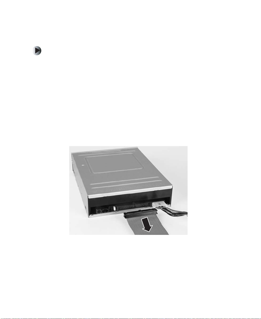
3 If you are removing a CD, DVD, diskette, tape, or Zip drive, disconnect
the wide, flat ribbon (data) cable from the drive that you are replacing.
Make sure that you pull the connector, not the cable. Note the orientation
of the red-striped edge of the data cable. You will attach the data cable to
your new drive using the same orientation. Go to Step 6.
- OR -
If you are removing a flash memory drive, go to the next step.
8
www.gateway.com
Page 13
Removing the dri ve
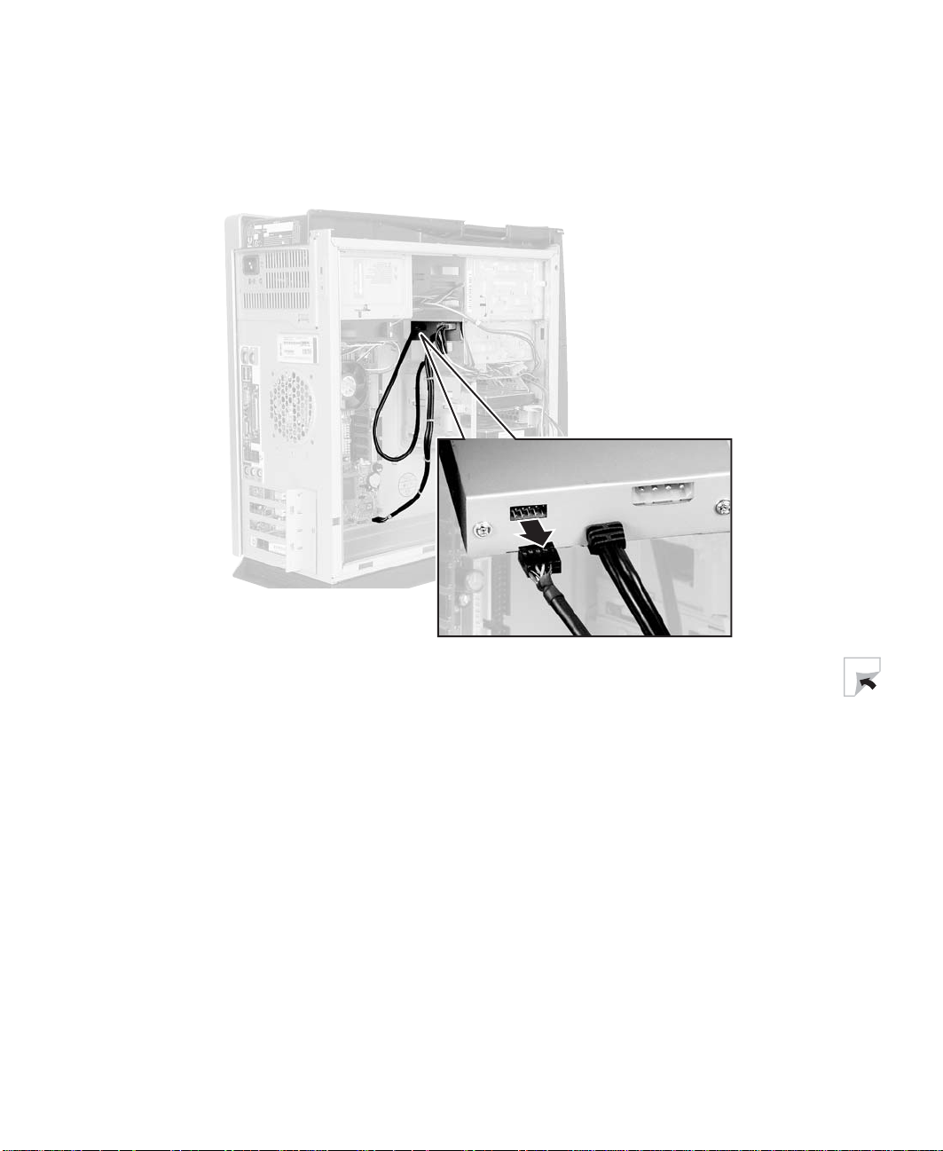
4 Disconnect the front panel USB round data cable from the back of the flash
memory drive. Make sure that you pull the connector, not the cable. Note
the orientation of the connector. You will attach the data cable to your
new drive using the same orientation.
www.gateway.com
9
Page 14
Chapter 2: Removing an E xisting Drive
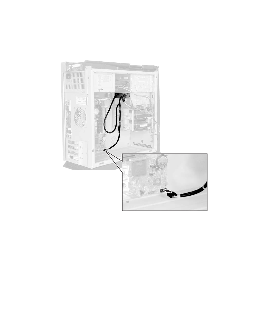
5 Disconnect the flash memory drive’s round data cable from the system
board. Make sure that you pull the connector, not the cable. Note the
orientation of the connector. You will attach the data cable from your new
drive using the same orientation.
10
www.gateway.com
Page 15
Removing the dri ve
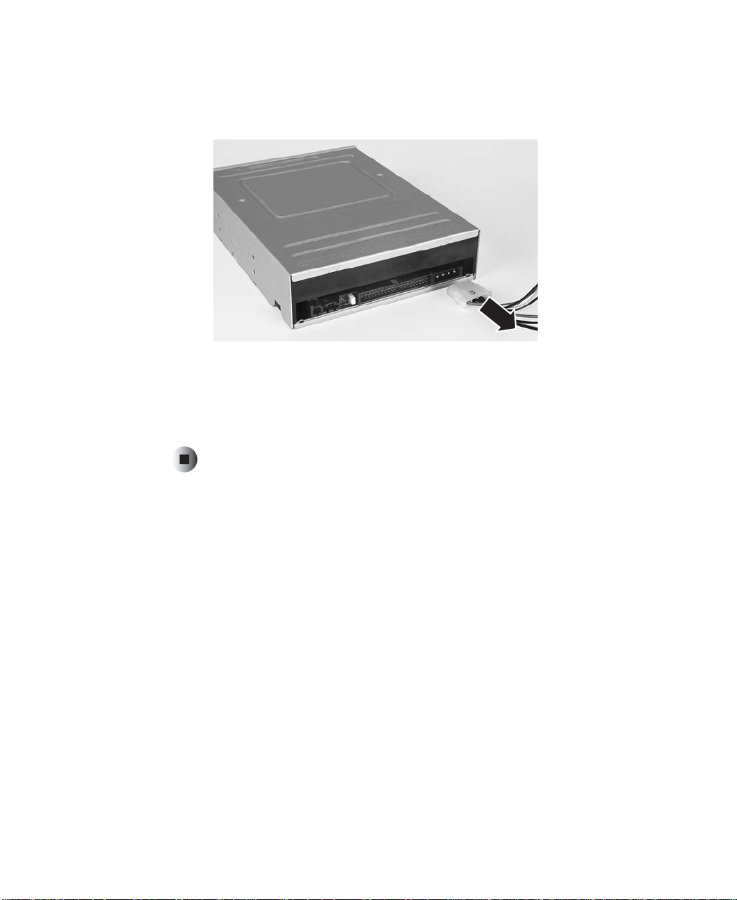
6 Disconnect the power cable from the back of the drive. Make sure that you
pull the connector, not the cable. Move the connector slightly side-to-side,
if necessary, to disconnect the cable.
7 See the documentation that came with your computer for instructions on
sliding the drive out of the computer case.
8 If this drive is a replacement for a failed drive, follow the instructions on
the return form to send the old drive back to Gateway for credit.
www.gateway.com
11
Page 16

Chapter 2: Removing an E xisting Drive
12
www.gateway.com
Page 17

Installing a
New Drive
Read this chapter to learn how to:
■ Configure IDE and SCSI drives
■ Install the drive
3
13
Page 18
Chapter 3: Installing a New Drive
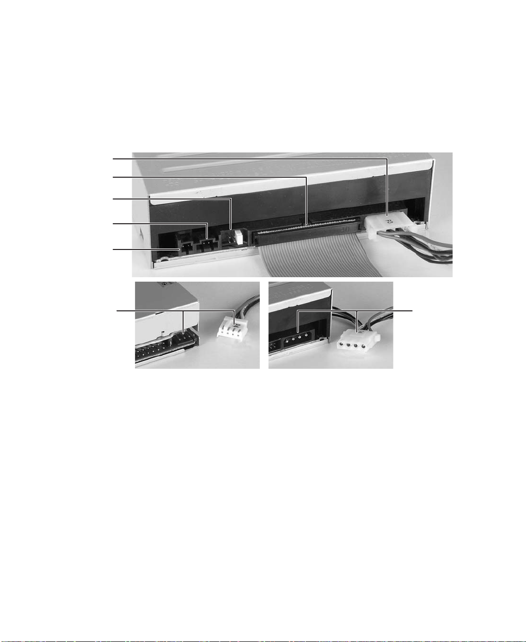
Identifying connectors
The following illustrations identify basic drive connectors.
CD, D VD, disket te, tape, and Zip drives
Pow er c a bl e
and connector
Data cable
and connector
Jumpe r blo ck
Analog audio
connector
Digital audio
connector
Diskette drive
power cable
and connector
■ Power connector. Both small and large power supply connectors attach
■ Data cable connector. Most data cable connectors are keyed with a notch.
■ Data cable. The IDE data cable is wider than the diskette drive data cable.
14
CD or DVD
drive power
cable and
connector
only one way. CD, DVD, tape, and Zip drives have a large power connector.
Diskette drives have a small power connector.
Some older drives, typically diskette drives, are not keyed.
One edge of the cable has a red stripe. The red-striped edge of the cable
should be aligned toward the Pin 1 end of the data cable connector.
Usually, this is the end of the connector that is nearest the power supply
connector. PIN 1 is usually labeled with a small arrow, the number “1,” or
a low number (for example, “2”).
www.gateway.com
Page 19

Identifying connectors
■ Jumper block. The jumper block is used to configure your IDE drive as a
master, slave, or cable select drive, or to configure your SCSI drive’s ID and
termination. A label on the drive shows which jumper/pin position
corresponds to which setting. Diskette drives do not have a jumper block.
■ Analog audio connector. If your drive is a CD or DVD drive, it may have
an analog audio connector.
■ Digital audio connector. If your drive is a CD or DVD drive, it may have
a digital audio connector.
Flash memory drives
Data cable connector
(Front panel USB port s)
■ Data cable connector. Connect the front panel USB data cable to the data
Data cable
Power
connector
cable connector.
■ Data cable. Connect the flash memory drive’s data cable to the
Front Panel USB connector on your system board.
■ Power connector. The large-type power supply connectors are keyed so
that they attach only one way.
www.gateway.com
15
Page 20

Chapter 3: Installing a New Drive
Configuring the new IDE drive
You can configure CD, DVD, diskette, and Zip drives as bootable drives. You can
use bootable drives to start up (boot) your computer with special bootable
media, such as a system diskette (a diskette that contains operating system files).
Your system board may contain as many as three controllers (where the wide
ribbon cables attach to the main system board or a host adapter add-in card).
One controller is for the diskette drive. Two are for IDE drives. One of the IDE
controllers is the primary controller and the other is the secondary controller.
Each IDE controller can contain two devices, a master device and a slave device.
Master drive
16
Slave drive
IDE data cable
www.gateway.com
Page 21

Configuring the new ID E drive
Master drives
If the drive you are installing is on the end of the cable, it is the master drive.
Master drives are typically bootable, meaning they are used to boot, or start,
your computer.
Your IDE drive should be configured as a master if it will be the only drive
connected to the IDE data cable or if there will be two drives connected to the
cable and the other drive is configured as a slave.
Important If you hav e only one drive it must be connected to the end
connector on the IDE cable.
Slave drives
If the drive you are installing is in the middle of the cable, it is the slave drive.
Slave drives are typically used for storing files and installing programs. You
cannot start your computer from the slave drive.
A slave drive is the secondary drive on either the primary or secondary IDE
controller. Configure your IDE drive as a slave drive if the drive will be one of
two drives connected to the IDE data cable and the other drive is configured
as a master drive.
Important If you are adding a drive and making the new drive the
master (boot) drive, the existing drive must be reconfigured
as a slave drive.
If there is already one drive connected to the cable before the new IDE drive
is installed, it is probably configured as a master. However, some IDE drives
require a different master/slave setting when two drives are connected. If you
have any problems, see the documentation that came with the existing IDE
drive for additional master/slave configuration information.
www.gateway.com
17
Page 22

Chapter 3: Installing a New Drive
Setting the IDE jumpers
IDE drives contain a jumper block. A jumper block is a set of pins located on
the drive. The jumper block is typically located on the rear of the drive,
although it may be located on the top or the bottom of the drive.
On some IDE drives, a jumper is placed over two of the pins to configure the
drive as the master (or single) drive or as the slave drive. IDE drives are labeled
with information about which set of pins must be used to make the drive master
or slave.
Other IDE drives use the cable select setting to configure the drive. Cable select
is a jumper setting that configures the drive as a master or slave drive based
on its position on the IDE cable. If both drives on the IDE data cable are
configured as cable select, the middle drive is the slave and the end drive is
the master.
If you are installing your new drive as a replacement drive, configure the new
drive settings so that they match your old drive settings. For example, if your
old drive was set as a Master drive, make sure to set the new drive as a
Master drive.
In order to maintain the same configuration (master, slave, or cable select), your
new drive may require different jumper settings than your current drive. Check
the label on your drive for the correct settings.
18
www.gateway.com
Page 23

Configuring the new ID E drive
To set the jumpers for an IDE drive:
1 Look at the jumper label to find the jumpers for setting a master, a slave,
or a cable select drive. The label is either a sticker on the drive, or it is
printed directly on the drive.
2 If both of the drives and the IDE data cable support cable select, set the
jumpers for the drives as cable select. IDE data cables that support cable
select should be labeled CS. Cable select makes the drive in the middle of
the cable the slave, and the drive at the end of the cable the master.
- OR -
If both drives do not support cable select, go to the next step.
3 If the drive is in the middle of the IDE data cable and you are going to
configure your drive as the slave drive, set the jumpers as
is not an option, set the jumpers as
- OR -
If the drive is at the end of the IDE data cable and you are going to
configure your drive as the master drive, set the jumpers as
Master A is not an option, set the jumpers as
Slave.
Master.
Slave A. If Slave A
Master A. If
www.gateway.com
19
Page 24

Chapter 3: Installing a New Drive
Last SCSI device
SCSI device
Configuring the new SCSI drive
If your computer contains SCSI devices, they are connected to a SCSI host
adapter add-in card.
To configure SCSI devices correctly on the SCSI cable, you must designate
(terminate) the ends of the chain and determine the order of the links (IDs)
between the ends of the SCSI chain.
Terminator
plug
Termination
A SCSI device has a terminator jumper which can be set to On (for the last
device on the cable) or Off (for devices in the middle). The terminator jumper
on the last device should be set to Off if the cable has a terminator plug attached
to the end.
(terminator=off,
ID set by jumper)
(terminator=off,
ID set by jumper)
SCSI host adapter
(ID=7,
SCSI data
ribbon cable
Generally, your computer’s SCSI host adapter is at one end of the cable and a
terminated device or terminator plug is at the other. The SCSI host adapter can
be set so you can start up from any device on the SCSI chain.
20
www.gateway.com
Page 25

Configuring the new SC SI drive
SCSI IDs
In addition to recognizing the ends of the SCSI chain, your computer needs
to designate the order of the links. For this reason, each device on the SCSI
chain requires a unique device ID. This ID can be any number between 0 and
15 (for Ultra Wide SCSI) other than 7, which is the factory preset for the host
adapter. The ID number (address) can be set on most SCSI devices by adjusting
jumpers on pins.
Setting the SCSI jumpers
SCSI drives contain a jumper block. A jumper block is a set of pins located on
the drive. On SCSI drives, a jumper is placed over two of the pins to configure
the SCSI drive’s termination setting. Other jumpers are placed over additional
sets of pins to configure the ID setting.
To set the jumpers for a SCSI drive:
1 Start your computer. During startup, SCSI ID numbers are identified on the
screen.
2 Make note of the SCSI ID numbers in use, then turn off your computer.
3 Look at the new drive’s jumper label to find the jumpers for setting the
SCSI drive’s termination and ID. The label is either a sticker on the drive,
or it is printed directly on the drive.
4 Set the drive’s SCSI ID to a number that is not being used by another SCSI
device.
www.gateway.com
21
Page 26

Chapter 3: Installing a New Drive
5 Check SCSI termination.
Example A: SCSI
Termination where a SCSI
tape drive is the last or only
SCSI device.
SCSI Host Adapter
(termination enabled)
SCSI tape drive
(termination enabled)
Example B:
SCSI Termination in a
computer with three
internal SCSI devices.
SCSI Host Adapter
(termination enabled)
SCSI tape drive
(termination disabled)
SCSI CD or DVD d rive
(termination disabled)
SCSI hard drive
(termination enabled)
If your drive will be the last device on the SCSI cable or the only device
on the cable, as shown in Example A, make sure that a jumper is installed
on the SCSI termination jumper pins or that a terminator plug is installed.
22
- OR -
If your drive will be in the middle of a SCSI chain, as shown in Example B,
remove the termination jumper. Make sure that the last SCSI device on
the cable has termination enabled or that a terminator plug is installed.
www.gateway.com
Page 27

Installing a drive
This section tells you how to install the drive and how to attach the cables.
To install a drive:
1 Slide the drive into the bay and secure the drive in the drive bay by
following the instructions in your computer user’s guide.
2 If your drive is a CD or DVD drive, connect the audio cable.
Important If you are adding a recordable CD or DVD drive to your
computer and the audio cable is attached to y our other C D
or DVD drive, you can remove the audio cable from your
other drive and attach it to your new drive.
3 Connect any unused power cable to the power supply connector on the
drive. Use a large power connector for CD, DVD, flash memory, Zip, and
tape drives, and use a smaller power connector for diskette drives.
Installing a drive
If you do not have enough power connectors, disconnect a power cable
from one of your drives and place the Y-adapter power cable that came
with the new drive on the end of the existing power cable to make two
power connectors.
www.gateway.com
23
Page 28

Chapter 3: Installing a New Drive
4 If you are installing a CD, DVD, diskette, tape, or Zip drive, connect the
data cable to the back of the drive. Be careful not to force the cable
connector or bend any of the pins. Follow the data cable from the
connection on the drive to the other end of the cable. Make sure that the
cable is connected securely to the data cable connector on the main system
board or the SCSI host adapter card. Go to Step 7
Caution Make sure that Pin 1 on the cable connects to Pin1 on the
drive or the drive will not function. Pin 1 on the drive is
typically located next to the 4-pin power cable. Check your
drive for a label indicating Pin 1. Pin 1 on the cable is
indicated by a red stripe on the edge of the cable.
24
- OR -
If you are installing a flash memory drive, go to the next step.
www.gateway.com
Page 29

Installing a drive
5 Connect the front panel USB round data cable to the back of the flash
memory drive. Be careful not to force the cable connector or bend any of
the pins.
www.gateway.com
25
Page 30

Chapter 3: Installing a New Drive
6 Connect the flash memory drive’s round data cable to the Front Panel USB
connector on the system board. Be careful not to force the cable connector
or bend any of the pins.
26
7 Check all cables in your computer. Make sure that all are connected
securely and that the cables are routed so that they will not bind or crimp
when you replace the computer case cover.
8 Replace the computer case cover. See the documentation that came with
your computer for instructions on replacing the cover.
9 Reconnect the external cables, then plug in the power cord.
www.gateway.com
Page 31

10 Turn on your computer.
■ If you installed a flash memory drive, you are finished. Stop here.
■ If you installed a diskette, CD, or DVD drive, go to “Configuring the
BIOS” on page 28.
■ If you installed a Zip drive and want it to be bootable, go to
“Configuring the BIOS” on page 28. If you do not want the Zip drive
to be bootable, go to “Installing Zip drive software” on page 30.
■ If you installed a Seagate tape drive, go to “Installing Seagate tape drive
software” on page 31.
Installing a drive
www.gateway.com
27
Page 32

Chapter 3: Installing a New Drive
Configuring the BIOS
If you are installing a SCSI drive, you do not need to configure the BIOS. The
installation is complete.
A boot drive is a drive that can be used to start your computer. If you have
multiple boot drives, you can specify their boot order. For example, setting a
diskette drive as a first boot device and setting a Zip drive as a second boot
device specifies that your computer first checks the diskette drive for a diskette
containing computer startup files, then it checks the Zip drive for a disk
containing computer startup files. If it fails to find either, it continues to start
from the hard drive.
Older computers may not have boot support for some drives. If your computer
does not support all drives, those drives will not be available in the boot device
section of the BIOS, so you must update your BIOS. For more information, see
your computer user’s guide.
After you install your drive, open the BIOS Setup utility and make sure that
the computer recognizes your drive and that the boot order of your computer
is correct.
To configure the BIOS:
1 Press F2 while restarting your computer to open the BIOS Setup utility.
Some older computer models require you to press F1 instead.
2 Press the right arrow key to open the Advanced menu, then set the master
and slave settings for the Primary and Secondary PCI IDE Interface to
Configured
Navigate among the menus and selections by pressing the arrow keys.
Change selection values by pressing + or - .
3 If you want to start (boot) from your drive, go to the next step. Otherwise,
go to Step 8.
4 If your computer uses a Phoenix BIOS, press the right arrow key to open
the
Boot Options menu.
- OR -
If your computer uses an AMI BIOS, configure each device independently
from the Main menu.
28
Auto
.
www.gateway.com
Page 33

Configuring the BIOS
5 Specify which devices you want to boot from, and in which order.
■ To specify your 3.5-inch, 1.44 MB diskette drive, select Floppy.
■ To specify the Zip drive, select Floptical if your computer is running
AMI BIOS, or select
BIOS.
Iomega Zip if your computer is running Phoenix
6 If your BIOS contains the option Removable Devices, set the boot order for
your multiple drives, then press E
SC.
7 If you removed the 3.5-inch diskette drive and did not replace it, go to
the next step. Otherwise, go to Step 10.
8 Press the right arrow key to display the Advanced menu, then press ENTER
to open the
Peripheral Configuration menu.
9 Set Floppy Disk Controller to Disabled, then press ESC.
10 Press the F10 key, then press ENTER.
■ If you installed a diskette, CD, or DVD drive, the installation is
complete.
■ If you installed a Zip drive, go to “Installing Zip drive software” on
page 30.
■ If you installed a Seagate tape drive, go to “Installing Seagate tape drive
software” on page 31.
www.gateway.com
29
Page 34

Chapter 3: Installing a New Drive
Installing Zip drive software
If you installed a Zip drive, you need to install additional software. Use the
Iomegaware™ CD to install your Zip drive software.
Important If you are installi ng in Wind ows NT 4.0, Service Pac k 4 (or
greater) is required for Zip compatibility. You must have
administrator privileges for your local computer to install
the Zip drive software and to run the ToolsNT utilities.
If you reinstall Windo w sNT 4.0, you may need to reinstall
the Zip drive software.
To install the Zip drive software:
1 Start your computer.
2 Insert the IomegaWare CD into your computer’s CD or DVD drive.
3 If the Iomega setup program starts automatically, go to Step 7.
- OR -
30
If the Iomega setup program does not start automatically, go to the
next step.
4 In Windows XP, click Start, then click My Computer. The My Computer
window opens.
- OR -
In Windows Me, Windows 2000, Windows 98, or Windows NT 4.0,
double-click the
My Computer icon. The My Computer window opens.
5 Click/Double-click the CD or DVD drive letter (usually D: or E:). The CD
or DVD drive window opens.
6 Double-click Setup.exe.
7 Install the software by following the on-screen instructions.
8 When the software installation is complete, restart your computer.
www.gateway.com
Page 35

Installing Seagate tape driv e software
Installing Seagate tape drive
software
If you installed a Seagate tape drive, you need to install additional software.
Use the Seagate Backup Exec™ CD to install your tape drive software.
Important If your computer is running Windows NT 4.0, you must
have administrator privileges for your local computer to
install the Seagate Backup Exec software.
If you reinstall Windo w sNT 4.0, you may need to reinstall
the Seagate Backup Exec software.
To install the Seagate tape drive software:
1 Start your computer.
2 Insert the Seagate Backup Exec CD into your computer’s CD or DVD drive.
3 If the Backup Exec setup program starts automatically, go to Step 7.
- OR -
If the Backup Exec setup program does not start automatically, go to the
next step.
4 In Windows XP, click Start, then click My Computer. The My Computer
window opens.
- OR -
In Windows Me, Windows 2000, Windows 98, or Windows NT 4.0,
double-click the
My Computer icon. The My Computer window opens.
5 Click/Double-click the CD or DVD drive letter (usually D: or E:). The CD
or DVD drive window opens.
6 Double-click Setup.exe.
7 Install the software by following the on-screen instructions.
8 When the software installation is complete, restart your computer.
www.gateway.com
31
Page 36

Chapter 3: Installing a New Drive
32
www.gateway.com
Page 37

Troubleshooting
This chapter provides some solutions to common drive
problems. Read this chapter to learn how to:
■ Understand general troubleshooting guidelines
■ Troubleshoot CD or DVD drive problems
■ Troubleshoot diskette drive problems
■ Troubleshoot flash memory drive problems
■ Troubleshoot Zip drive problems
■ Troubleshoot tape drive problems
■ Get technical support
4
33
Page 38

Chapter 4: Troubleshoo ting
General troub leshooting guidelines
If your computer does not recognize the new drive, try these troubleshooting
tips before calling Gateway Technical Support:
■ Review the installation procedures. Make sure that you did not skip any
of the steps.
■ Reconnect the power cable on the drive.
■ Reconnect the data ribbon cable on the drive. Make sure that the red-stripe
edge of the data ribbon cable aligns with Pin 1 on your drive.
■ Replace the data ribbon cable with the new cable that was included in the
drive kit to see if the old cable is defective and needs to be replaced.
■ Make sure that the jumper settings on the back of the drive are set correctly.
Review the instructions on configuring the drive to see if you placed the
jumpers over the correct pins.
■ Check your BIOS Setup utility to see if your drive settings are correct.
34
www.gateway.com
Page 39

CD or D VD drive
Some of the steps in this section may require you to remove the computer case
cover. Follow “Preventing static electricity discharge” on page 3 when working
inside your computer.
Y our computer does not r ecognize the CD or D VD drive.
■ Make sure that the CD or DVD label is facing up, then try again.
■ Try a different CD. Occasionally CDs are flawed and cannot be read by
the CD or DVD drive.
■ Shut down and restart your computer.
■ Clean the disc.
■ Open the BIOS Setup utility by pressing F2 while restarting your computer.
(Some older computer models require you to press F1 instead.) Make sure
that the IDE controllers are enabled.
■ Make sure that the drive is configured correctly, and reconfigure the drive,
if necessary. See “Installing a New Drive” on page 13.
■ Open your computer and make sure that the cables are connected correctly
to the CD or DVD drive and the system board IDE connector.
CD or DVD drive
■ If you have a SCSI device in your computer, check the cable connected to
the SCSI card. If the CD or DVD drive is the last drive on the cable (the
drive farthest from the card), make sure that the CD or DVD drive is
terminated.
The CD or DVD drive makes a buzzing noise.
High speed compact disc drives may vibrate or make noise. Discs that are
warped, have an imperfect hole in the middle, or have an off-center or unequal
image printed on them may cause vibrations. Even though the disc is vibrating
or making a noise, that is not necessarily a problem. As long as the data on
the disc can be read, the disc and the drive are fine. Such vibrations and noises
are normal side effects with many computer components.
www.gateway.com
35
Page 40

Chapter 4: Troubleshoo ting
Audio CD does not produce sound.
■ Make sure that the CD label is facing up, then try again.
■ Some C D s have copy p rotec tion s o ftwa r e. You m a y not b e able to pla y the s e
CDs on your computer.
■ If you have two CD drives, try the other drive.
■ Check the speaker cables. Make sure that they are connected correctly and
securely.
■ Make sure that the volume controls are turned up. For more information
about volume controls, see the documentation that came with your
computer.
■ Make sure that mute controls are turned off. For more information about
volume controls, see the documentation that came with your computer.
■ Shut down and restart your computer.
■ Clean the CD.
A DVD movie wil l not play .
■ Make sure that the label is facing up, then try again.
■ Shut down and restart your computer.
■ Clean the DVD.
DVDs and drives contain regional codes that help control DVD title exports and
help reduce illegal disc distribution. To be able to play a DVD, the disc’s regional
code and your DVD drive’s regional code must match.
The regional code on your DVD drive is determined by your computer’s delivery
address. The regional code for the disc is on the disc, disc documentation, or
packaging. The regional code for the United States and Canada is 1, and the
regional code for Mexico is 4.
If the DVD movie does not play, the disc’s regional code and your regional code
may not match.
36
www.gateway.com
Page 41

Diskette drive
Some of the steps in this document may require you to remove the computer
case cover. Follow “Preventing static electricity discharge” on page 3 when
working inside your computer.
Y our computer cannot access the di skette drive.
You may not be able to copy information to or from the diskette drive if:
■ The diskette is write-protected.
■ The diskette drive or diskette is damaged.
■ The settings in the BIOS are incorrect.
■ The cable that goes from the back of the diskette drive to the system board
or controller card is defective or not connected securely.
■ There is a conflict within the computer with some newly added hardware
or software.
■ The drive is damaged or a password has been enabled.
Diskette drive
Y our computer cannot access the di skette.
The diskette may be damaged. Reformat the diskette, or try another diskette.
To format a diskette:
1 Insert a diskette into the diskette drive.
2 In Windows XP, click Start, then click My Computer. The My Computer
window opens.
- OR -
In Windows Me, Windows 2000, Windows 98, or Windows NT 4.0
double-click the
My Computer icon. The My Computer window opens.
www.gateway.com
37
Page 42

Chapter 4: Troubleshoo ting
3 Right-click the icon for the diskette drive, click Format, then click
Start.
Caution Any information on the diskette is deleted when you format
Y our computer does not recognize the diskette drive.
■ If the diskette drive is identified incorrectly in the BIOS, you may not be
able to start from or format a diskette.
To check the diskette drive identification in the BIOS Setup utility:
1 Open the BIOS Setup program by pressing F2 while restarting your
computer. (Sometimes older computer models require you to press
F1 instead.)
2 Make sure that the drive settings correspond with the drive type (for
example,
or diskette drive A).
the diskette.
3.5-inch, 1.44 MB is the current standard for diskette drive 0
38
3 Check the Security section of the BIOS Setup utility and remove the
Supervisor password if one has been set.
The supervisor password causes the diskette drive to display error
messages identical to those usually associated with a defective
diskette drive or cable.
www.gateway.com
Page 43

Diskette drive
■ If you have checked the BIOS settings and the settings are correct, the
problem may be a poor connection between the diskette drive and the
system board. Because no locking clips hold the diskette drive cable in
place, the cable may need to be reseated.
To reseat the cable:
1 Turn off your computer, then remove the computer case cover
following the static electricity precautions on page 3.
See the documentation that came with your computer for
instructions on removing your computer case cover.
2 On the back of the diskette drive, find the power cable and the flat,
gray ribbon cable.
3 Firmly pull the ribbon cable straight off the back of the diskette drive
(pull the connector, not the cable) and press it firmly back in place
the same way you took it off.
4 Trace the cable to its connector on the system board. Unplug the
cable (pull the connector, not the cable), then plug it back in, making
sure that it fits securely into the keyed connector.
5 Replace the computer case cover, reconnect the cables, then restart
your computer. Try to start from a system diskette and try to format
a diskette. For more information, see “To format a diskette:” on
page 37.
6 If you are still unable to start from a system diskette or format a
diskette, shut down your computer, then open the computer case
cover.
7 Pull the power cable off the back of the drive (pull the connector,
not the cable).
8 Replace it with another available power cable that is the same size
as the one originally on the drive.
9 Replace the computer case cover, reconnect the cables, then restart
your computer. Try to start from a system diskette and try to format
a diskette. For more information, see “To format a diskette:” on
page 37.
www.gateway.com
39
Page 44

Chapter 4: Troubleshoo ting
■ If you have recently added any hardware to the computer, such as a tape
backup unit, sound card, scanner, or network card, try removing these
items from the computer one at a time.
Each time you remove an item, try to start your computer using a system
diskette or try to format a diskette. If the diskette drive works, it is possible
the hardware that was added may be conflicting with the diskette drive.
Re-configure the new hardware or try replacing it to see if the problem
persists.
■ If you recently added new software to the computer, try removing the new
software. If that solves the problem, contact the software publisher for
additional information.
The diskette drive light stay s on continuously.
If the light on the diskette drive(s) stays on continuously from the time your
computer is started, the data cable on the system board or controller card may
be on backwards.
To fix the data cable connection:
1 Shut down your computer.
2 Open the computer case.
3 Locate where the data cable is attached to the system board.
4 Pull the cable off gently (pull the connector, not the cable).
5 Turn the cable around 180 degrees and put it back onto the system
board.
6 Close the computer case.
If you started having diskette drive problems after adding a tape backup unit,
try using the additional diskette cable that came with the tape backup unit kit.
Instructions for this operation are included in the tape backup unit kit.
40
www.gateway.com
Page 45

Diskette drive error messages
Diskette Drive 0 Failure or Diskette Drive 1 Failure
This error is usually seen as the computer starts up.
■ Check the BIOS to make sure that the drives are identified correctly.
■ Open the computer and reseat the diskette drive cable.
■ Try another diskette drive cable.
Not ready reading drive A or Not ready reading drive B
■ Make sure that the drives are correctly identified in the BIOS. For more
information, see “Configuring the BIOS” on page 28.
■ Make sure that the drive cables are connected securely. For more
information, see “Installing a drive” on page 23.
■ If the supervisor password is enabled in the BIOS, remove the password.
Inv alid drive speci fication
This error can be caused by incorrect BIOS settings including the diskette drive
not being identified at all. Check the BIOS to make sure that the drives are
identified correctly. For more information, see “Configuring the BIOS” on
page 28.
Diskette drive
Inv alid media type
This error may occur if you are trying to format a diskette that is defective or
if you are trying to use a media type that is incompatible with your diskette
drive.
Error selecting drive
This error occurs primarily in Windows when you attempt to access the diskette
drive without a diskette inserted.
Non-system disk or disk err or
This error occurs if you have a diskette other than a system (boot) diskette in
the diskette drive as you start up the computer. If you have a bootable system
diskette in the drive and you still receive this error, the diskette drive cable may
not be connected securely. See “To reseat the cable:” on page 39.
Always make sure that the diskettes you are attempting to use are high density,
good quality diskettes.
www.gateway.com
41
Page 46

Chapter 4: Troubleshoo ting
Flash memory drive
Some of the steps in this document may require you to remove the computer
case cover. Follow “Preventing static electricity discharge” on page 3 when
working inside your computer.
The green LED does not turn on.
■ Make sure that your computer is receiving power.
■ Make sure that the power cable connection to the flash memory drive is
secure.
■ Make sure that there is a flash memory card in the drive.
The green LED blinks on and off.
The green LED lets you know that you have inserted your flash memory card
into the flash memory drive correctly. After you insert the memory card into
the drive slot, the green LED, next to the drive slot, blinks on and off several
times. When the memory drive recognizes the memory card, the LED stays on.
The green LED blinks on and off as data is read from and written to a memory
card.
Camera gives an error message after fo rmatting a 64 MB, or larger ,
memory card in Windows XP.
Windows XP automatically selects FAT32 when formatting memory cards larger
than 64 MB. However, most memory cards use FAT12, FAT16, or other
proprietary formats. Reformat the memory card in the camera or other device
that you use the card in.
MP3 player cannot read m usic files on memory card.
Some MP3 players use a proprietary file format that Windows XP does not
support. Instead of copying files from your computer to the memory card,
connect the MP3 player to the computer and use the software that was included
with the player to upload the songs to the player.
Write Protected err or when trying to copy files to a memory card.
Memory Stick and Secure Digital (SD) memory cards have a physical lock that
can be used to prevent data from being written to or erased from the memory
card. Look for a small slide switch on the bottom of the card. If you want to
write data to the memory card, make sure that the switch is in the unlocked
position.
42
www.gateway.com
Page 47

Cannot copy songs from a Secure Digital memory car d to my
computer.
Secure Digital memory cards have copy protection algorithms that prevent you
from copying copyrighted material from the card to another device. You can
play copyrighted files from the memory card, but you cannot copy the
copyrighted files from the memory card.
Zip drive
Some of the steps in this section may require you to remove the computer case
cover. Follow “Preventing static electricity discharge” on page 3 when working
inside your computer.
The green busy light on the Zip drive does not turn on.
■ Make sure that your computer is receiving power.
■ Make sure that the power cable connection to the Zip drive is secure.
■ Make sure that there is a disk in the drive.
Zip drive
The Zip drive is n ot assigned a drive letter , or the Iomega sof tware
cannot find the Zip drive.
■ Make sure that Pin 1 is connected correctly on all IDE data cable
connections. The red stripe on the data cable must align with Pin 1 on
each connection. If the cable does not have a keyed connector, make sure
that the connector is covering all of the pins. For more information, see
“Installing a drive” on page 23.
■ Make sure that the Zip drive is configured correctly. See “Configuring the
new IDE drive” on page 16 or “Configuring the new SCSI drive” on
page 20, depending on the type of drive that you have.
■ If there is another drive on the same IDE controller, make sure that it is
configured correctly. See the documentation that accompanied the other
IDE drive for configuration information. (Often this information is on the
drive case.)
■ Make sure that BIOS support for the Zip drive is enabled in the BIOS. If
you are unable to enable BIOS support for the Zip drive in the BIOS Setup
utility and the Zip drive does not appear on the computer, then your
computer may have an incompatible BIOS that does not correctly
understand IDE drives. Download and install an updated BIOS from the
Gateway Web site at support.gateway.com
www.gateway.com
.
43
Page 48

Chapter 4: Troubleshoo ting
■ Make sure that the software drivers for the Zip drive are correctly installed.
See “Installing Zip drive software” on page 30.
■ If your computer’s operating system is Windows 98, make sure that the
operating system is running in 32-bit mode (Protected mode).
To determine if the operating system is running in 32-bit mode:
1 Right-click the My Computer icon, then click Properties.
2 Click the Performance tab and confirm that File System and Virtual
Memory
3 If the mode is 16-bit, see the Windows documentation for
instructions on changing the operating system to 32-bit.
■ Some IDE hard drives do not work correctly unless they are in a certain
position on the IDE cable. You may need to reverse the position of the
master drive and the Zip (slave) drive on the cable for the drives to work
correctly.
■ If your computer still does not recognize the Zip drive, the existing IDE
master drive may not allow access to a slave drive on the same cable. Try
installing the Zip drive on the secondary IDE controller.
are listed as 32-bit.
Y our computer does not recognize a sla ve drive connected to the
same IDE cable as a Zip master drive.
■ Make sure that Pin 1 is connected correctly on all IDE data cable
connections. The red stripe on the data cable should align with Pin 1 on
each connection. If the cable does not have a keyed connector, make sure
that the connector is covering all of the pins.
■ Make sure that the slave drive is jumpered correctly as a slave. See the
documentation that came with the slave drive for configuration
information. (Often this information is on the drive case.)
■ Some IDE hard drives do not work correctly unless they are in a certain
position on the IDE cable. You may need to reverse the position of the
slave drive and the Zip (master) drive on the cable for the slave drive to
work correctly.
■ If your computer still does not recognize the slave drive, configure the
jumper settings on the Zip drive for the Cable Select option. For more
information, see “Setting the IDE jumpers” on page 18.
44
www.gateway.com
Page 49

T ape drive
Some of the steps in this section may require you to remove the computer case
cover. Follow “Preventing static electricity discharge” on page 3 when working
inside your computer.
After a period of successful operation, the tape drive appears to fail
during a backup or restore.
■ Make sure that all cables are securely connected and jumpers are set
appropriately.
■ Turn your computer off, then restart your computer. Re-run the backup
software, making sure that no other programs (such as virus scanners) are
running.
■ Remove the tape cartridge, then reinsert it into the drive.
■ Try a different tape cartridge, preferably one that has never been used
before.
■ Make sure that you are using the correct type of tape cartridge for your
tape drive model.
Tape drive
■ Re-tension the tape, see “Re-tensioning a backup tape.” on page 45.
■ Clean the tape drive, see “Cleaning a tape drive.” on page 46.
Re-tensioning a backup tape.
Tapes must be re-tensioned frequently to ensure data integrity and optimize
drive performance. If you ever have a problem reading a tape, re-tensioning
may solve the problem. The tape drive software has a utility for re-tensioning
tapes. Tape re-tensioning is recommended whenever:
■ A cartridge is being used for the first time
■ A cartridge has not been used for over a month
■ A cartridge has been dropped
■ A cartridge has been shipped from one location to another
■ A cartridge has been exposed to a significant change in temperature
For best performance, cartridges used for daily backups should be re-tensioned
at least once a week.
www.gateway.com
45
Page 50

Chapter 4: Troubleshoo ting
Cleaning a tape drive.
The tape drive needs to be cleaned. You can clean the drive using one of two
methods:
■ Use a Travan cleaning cartridge
■ Clean the drive head manually
To clean the drive head manually:
1 Moisten a clean, foam-tip swab in isopropyl alcohol. The swab
should be wet but not dripping.
2 Hold the drive access door open and gently wipe the tape head using
an up-and-down motion.
3 Use a second swab saturated in isopropyl alcohol to wipe the capstan.
The capstan is the flat roller just to the left of the tape head. Rotate
the capstan and clean its entire surface. Allow at least three minutes
for the alcohol to dry before using the drive.
Y our computer does not recognize y our new IDE tape drive.
■ Make sure that you have correctly installed the Seagate Backup Exec
software.
■ Make sure that all cables are attached firmly.
■ Check with the manufacturer of your IDE controller chip set to make sure
that you have the latest drivers for your operating system. Outdated or
incorrect drivers provide limited hardware support and can result in
Windows being unable to detect your tape drive.
■ You may need to reconfigure your tape drive as the master or slave drive
using the Master/Slave jumpers.
If the tape drive is the only device on the IDE cable, set the jumper to
configure it as the master.
If there are two IDE devices on a single cable, make sure that the tape drive
is configured as the slave. Configure the other device as the master.
46
www.gateway.com
Page 51

Tape drive
Y our computer does not recognize y our new SCSI tape drive or other
SCSI devices:
■ Make sure that you have correctly installed the Seagate Backup Exec
software.
■ Make sure that all cables are attached securely.
■ Check the SCSI ID of each device in the SCSI chain to make sure that no
two devices have the same ID number (the controller is usually ID 7 and
the bootable hard drive is usually ID 0).
■ Make sure that SCSI termination is set correctly for each SCSI device.
Termination should be enabled for SCSI devices at each end of the SCSI
chain. All other SCSI devices must have termination disabled.
■ Make sure that you are using the latest drivers for your SCSI host adapter
and operating system. Contact the manufacturer of your SCSI host adapter
for driver information.
www.gateway.com
47
Page 52

Chapter 4: Troubleshoo ting
Getting technical support
If none of these solutions resolve your drive problems, contact Gateway
Technical Support for further assistance. For information about the different
methods for contacting Gateway Technical Support, see the user’s guide that
came with your computer.
48
www.gateway.com
Page 53

Safety,
Regulatory , and
Legal Information
Regulatory compliance statements
United States of America
Federal Communications Commission (FCC)
Unintentional emitter per FCC Part 15
This device has been tested and found to comply with the limits for a
Cl ass B dig ita l dev ice, pur sua nt to Pa rt 15 of t he F CC r ules . Th ese l imi ts
are designed to provide reasonable protection against harmful
interference in a residential installation.
A
49
Page 54

Appendix A: Safety, Reg ulatory, and Legal I nformation
This equipment generates, uses, and can radiate radio frequency energy and, if not installed and
used in accordance with the instructions, may cause harmful interference to radio or television
reception. However, there is no guarantee that interference will not occur in a particular
installation. If this equipment does cause interference to radio and television reception, which can
be determined by turning the equipment off and on, the user is encouraged to try to correct the
interference by one or more of the following measures:
■
Reorient or relocate the receiving antenna
■
Increase the separation between the equipment and receiver
■
Connect the equipment to an outlet on a different circuit from that to which the receiver is
connected
■
Consult the dealer or an experienced radio/TV technician for help.
Compliance Accessories: The accessories associated with this equipment are: shielded video cable
when an external monitor is connected. These accessories are required to be used in order to
ensure compliance with FCC rules.
Caution Changes or modifications not expressly approved by
Gateway could void the FCC c om pli anc e and ne gate your
authority to operate the product.
Canada
Industry Canada (IC)
Unintentional emitter per ICES-003
This digital apparatus does not exceed the Class B limits for radio noise emissions from digital
apparatus as set out in the radio interference regulations of Industry Canada.
Le présent appareil numérique n’émet pas de bruits radioélectriques dépassant les limites
applicables aux appareils numériques de Classe B prescrites dans le règlement sur le brouillage
radioélectrique édicté par Industrie Canada.
50
www.gateway.com
Page 55

Regulatory compli ance statements
Laser safety statement
All Gateway systems equipped with CD and DVD drives comply with the appropriate safety
standards, including IEC 825. The laser devices in these components are classified as “Class 1 Laser
Products” under a US Department of Health and Human Services (DHHS) Radiation Performance
Standard. Should the unit ever need servicing, contact an authorized service location.
Warning Use of controls or adjustments or performance of
procedures other than those specified in this manual may
result in hazardous radiation exposure. To prevent
exposure to lase r beams , do no t try to open the enc losure
of a CD or DVD drive.
California Pr oposition 65 W arning
Warning This product contai ns ch em ic als, including lead, known to
the State of Calif ornia to cause cancer and/ or birth defects
or reproductive harm.
www.gateway.com
51
Page 56

Appendix A: Safety, Reg ulatory, and Legal I nformation
Notices
Copyright © 2003 Gateway, Inc.
All Rights Reserved
14303 Gateway Place
Powa y, CA 92064 USA
All Rights Reserved
This publication is protected by copyright and all rights are reserved. No part of it may be reproduced or
transmitted by any means or in any f orm, without prior consent in writing from Gateway.
The information in this manual has been carefully checked and is belie ved t o be accurate. Howe ver , changes are
made periodically. These changes are incorporated in newer publication editions. Gateway ma y improve and/or
change products described in this publication at any time. Due to continuing system improvements, Gatewa y is
not responsible for inaccurate information which may appear in this manual. F or the latest product updates,
consult the Gate wa y W eb site a t www.gateway.com
exemplary, incidental, or consequential damages resulting from any defect or omission in this manual, even if
advised of the possibility of such damages.
In the interest of continued product development, Gatew ay reserves the right to make improv ements in this
manual and the products it describes at any time, without notices or obligation.
T rademark Acknowledgments
1-800-GA TEW AY , Activ eCPR, ALR, AnyKey, black-and-white spot design, CrystalScan, Destination, DestiV u, EZ
Pad, EZ P oint, Field Mouse, Gatewa y 2000, Gatewa y Country , gate wa y . net, Gatewa y stylized logo , P erfect
Scholar, Solo , TelePath, Vivitron, stylized “G” design, and “You’ve got a friend in the business” slogan are
registered trademarks and black-and-white spotted box logo, GATEWAY, Gateway Astro, Gate way@W ork,
Gateway Connected touch pad, Gatewa y Connected music play er , Gatewa y Cyber:)Ware, Gatew ay
Education:)W are, Gat ew ay Fle x Cas e, Gate wa y Gaming:) Wa re, Gat ewa y GoBac k, Gate wa y Gold, Gatew ay
Learning:)Ware, Gateway Magazine, Gatew ay Micro Server , Gatewa y Money:)Ware, Gatewa y Music:)Ware,
Gateway Networking Solutions, Gatewa y Online Network (O.N.) solution, Gate way Photo:)W are, Gatew ay
Professional PCs, Gateway Profile, Gatewa y Solo, green stylized GATEWAY , green stylized Gate wa y logo,
Gateway Teacher:)Ware, Gateway Video:)W are, HelpSpot, Inf orManager, J ust click it!, Learn@Gatewa y, Kids
BackPack, SER VE-T O-ORDER, Server Watchdog, the Spotted G Gatewa y Logo and the Spotted G Logo ,
SpotShop, Spotshop.com, and Your:)Ware are trademarks of Gateway, Inc. Intel, Intel Inside logo, and P entium
are registered trademarks and MMX is a trademark of Intel Corporation. Microsoft, MS, MS-DOS, and Windows
are trademarks or registered trademarks of Microsoft Corporation. All other product names mentioned herein are
used for identification purposes only , and may be the trademarks or registered trademarks of their respective
companies.
. In no event will Gate way be liab le for di rect, indirect, special,
52
www.gateway.com
Page 57

Page 58

MAN US REMOVE STORAGE INST R6 5/03
 Loading...