


 Loading...
Fujitsu PLASMAVISION P55XHA51WS, PLASMAVISION P42VHA51WS, PLASMAVISION P42HHA51WS, PLASMAVISION P50XHA51WS Manual

USER'S MANUAL 

(Specification and Part Names)
WIDE PLASMA DISPLAY P42VHA51W P42HHA51W/P50XHA51W/P55XHA51W P42HHA51A/P50XHA51A/P55XHA51A
|
Contents |
|
Page |
Before Use |
|
• INFORMATION......................................................................................................... |
E-2 |
• INSTALLATION ........................................................................................................ |
E-3 |
Usage |
|
• PART NAMES AND FUNCTIONS............................................................................ |
E-4 |
Others |
|
• OPTIONS.................................................................................................................. |
E-8 |
• MAIN SUPPORTED SIGNALS................................................................................. |
E-9 |
• SPECIFICATIONS.................................................................................................. |
E-10 |
|
|
Before using the display, read the User’s manual (1/2) and the User’s manual (2/2) carefully so that you know how to use the display correctly.
Refer to this manual whenever questions or problems about operation arise. Be sure to read and observe the safety precautions (see the separate "Safety Precautions" manual).
Keep this manual where the user can see it easily.
*Installation and removal require special expertise. Consult your product dealer for details.
*When "English" is selected at "Language" of the on-screen display, "colour" will be displayed but "color" is described in this manual.
*The residential warranty for "A model" is enclosed in accessories.
*The last digit of MODEL NO. (10 digit alphanumeric characters) indicated on the product means the body color indication alphabet or the management number.
*The illustration of external appearance is for 42" model.
Please acknowledge some differences in the actual product of other models.
Pусский Português Italiano Français Español Deutsch English
÷–Œƒ

 INFORMATION
CHECKING ACCESSORIES
One power cable |
Two small |
Two big |
Three user's manuals |
One remote control |
|
|
ferrite cores |
ferrite cores |
|
|
|
|
|
|
Manual |
Manual |
|
|
|
|
Manual |
|
|
|
No.:ZCAT1518-0730 |
No.:SFT-72SN |
|
|
|
|
Mfr.:TDK |
Mfr.:TKK |
|
|
|
|
Two AA batteries |
One residential |
|
|
|
|
|
warranty |
|
|
|
|
|
(for the A model) |
|
|
|
ATTACHING THE FERRITE CORES
The ferrite cores are used to reduce noise. Attach them correctly as shown in the following illustrations.
Be sure to turn off power of the plasma display and external equipment before making any connections.
Carefully check the terminals for position and type before making any connections.
Loose connectors can result in picture or color problems. Make sure that all connectors are securely inserted into their terminals.
Two big ferrite cores
When connecting the cord to the power input terminal, RS232C input terminal, attach one of these ferrite cores to the cord and the cable near the terminal.
Power Cord 
 RS232C Cable
Ferrite Core |
Ferrite Core |
|
Two small ferrite cores
When connecting a cable to the external speaker output terminal attach one of these ferrite cores to the cable near the terminal.
Ferrite Core |
Ferrite Core |
E-2
 INSTALLATION
To prevent the plasma display's internal components from overheating, make sure that the plasma display is installed in a well-ventilated location.
Be sure to use the optional stand, wall-mounting unit or the other mounting unit when installing the plasma display. Also, be sure that your dealer performs the installation.
See the appropriate instruction manual for additional information on the mounting hardware you select.
To prevent an accident and ensure safety in the event of an earthquake, fix the plasma display securely into the position as described below.
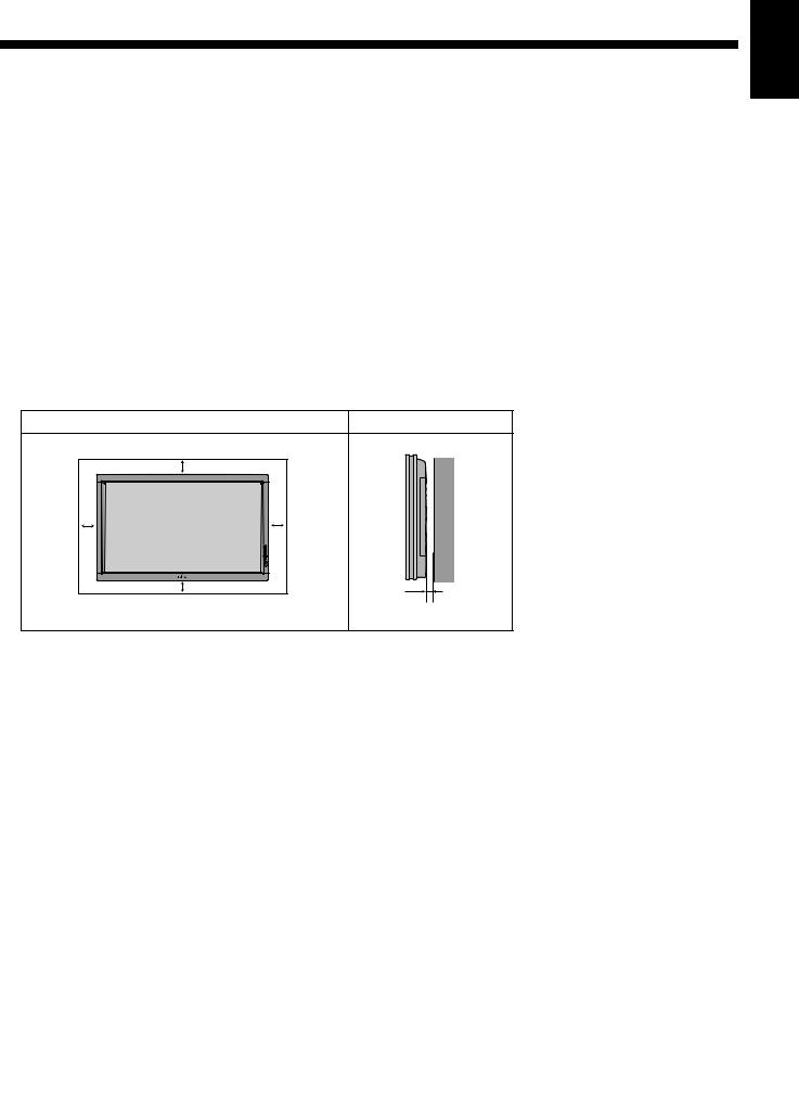
Use the diagram below to determine how much space is needed to ensure proper heat radiation. This is a minimum space requirement; therefore, provide at least as much space as indicated below.
*Make sure that the plasma display is installed in a location where the temperature can be maintained between 0°C and 40°C (between 32°F and 104°F)
*Never attempt to tilt the plasma display sideways or backward.
*To prevent the power cord and other cables from being accidentally pulled, make sure that they run along the wall or through corners.
*To prevent accidents and ensure safety in the event of an earthquake, secure the plasma display to prevent it from tipping over.
Display Section |
|
|
|
Front |
|
|
Side |
Upper |
|
(cm) |
(cm) |
10 |
|
|
|
10 |
10 |
Right |
Wall |
Left |
|
|
|
5 |
|
|
|
Lower |
|
|
3.5 (for 42"/50") |
|
|
|
|
|
|
|
5 (for 55") |
Pусский Português Italiano Français Español Deutsch English
Note
•The external view is meant to be a representation of the actual unit and is not to scale; therefore, it may differ from the actual shape and size of the product.
•Due to the fragile and highly precise equipment, it is very important to pack properly before transportation using only the packing materials provided.
Reference
See P. E-8 for more information on options.
÷–Œƒ
E-3
Loading...