


Statement:
This manual is the intellectual property of Foxconn, Inc. Although the information in this manual may be changed or modified at any time, Foxconn does not obligate itself to inform the user of these changes.
Trademark:
All trademarks are the property of their respective owners.
Version:
User’s Manual V1.0 for P35AP-S Series motherboard.
P/N: 3A220JQ00-000-G
Symbol description:
Note: refers to important information that can help you to use motherboard better.
Attention: indicates that it may damage hardware or cause data loss, and tells you how to avoid such problems.
Warning: means that a potential risk of property damage or physical injury exists.
More information:
If you want more information about our products, please visit Foxconn’s
website: http://www.foxconnchannel.com
 WEEE: The use of the symbol indicates that this product may not be treated as household waste. By ensuring this product is disposed of correctly, you will help prevent potential negative consequences for the environment and human health, which could otherwise be caused by inappropriate waste handling of this product. For more detailed information about recycling of this product, please contact your local city office, your household waste disposal service or the shop where you purchased the product.
Declaration of conformity
HON HAI PRECISION INDUSTRY COMPANY LTD
66 , CHUNG SHAN RD., TU-CHENG INDUSTRIAL DISTRICT,
TAIPEI HSIEN, TAIWAN, R.O.C.
declares that the product
Motherboard
P35AP-S
is in conformity with
(reference to the specification under which conformity is declared in accordance with 89/336 EEC-EMC Directive)
þ EN |
55022: 1998/A2: 2003 |
Limits and methods of measurements of radio disturbance |
||||
þ EN |
|
|
characteristics of information technology equipment |
|||
61000-3-2/:2000 |
Electromagnetic compatibility (EMC) |
|||||
|
|
|
Part 3: Limits |
|||
|
|
|
Section 2: Limits for harmonic current emissions |
|||
þ EN |
|
|
(equipment input current <= 16A per phase) |
|||
61000-3-3/A1:2001 |
Electromagnetic compatibility (EMC) |
|||||
|
|
|
Part 3: Limits |
|||
|
|
|
Section 2: Limits of voltage fluctuations and flicker in low-voltage |
|||
þ EN |
|
|
supply systems for equipment with rated current <= 16A |
|||
55024/A2:2003 |
Information technology equipment-Immunity characteristics limits |
|||||
|
|
|
and methods of measurement |
|||
Signature : |
|
|
Place / Date : TAIPEI/2007 |
|||
|
|
|
|
|
|
|
Printed Name : James Liang |
Position/ Title : Assistant President |
|
|
|
|

Declaration of conformity
Trade Name: |
FOXCONN |
Model Name: |
P35AP-S |
Responsible Party: |
PCE Industry Inc. |
Address: |
458 E. Lambert Rd. |
|
Fullerton, CA 92835 |
Telephone: |
714-738-8868 |
Facsimile: |
714-738-8838 |
Equipment Classification: |
FCC Class B Subassembly |
Type of Product: |
Motherboard |
Manufacturer: |
HON HAI PRECISION INDUSTRY |
|
COMPANY LTD |
Address: |
66 , CHUNG SHAN RD., TU-CHENG |
|
INDUSTRIAL DISTRICT, TAIPEI HSIEN, |
|
TAIWAN, R.O.C. |
SupplementaryInformation: |
|
This device complies with Part 15 of the FCC Rules. Operation is subject to the following two conditions : (1) this device may not cause harmful interference, and (2) this device must accept any interference received, including interference that may cause undesired operation.
Tested to comply with FCC standards.
Signature : |
Date : 2007 |

|
|
Table of Contents |
|
Chapter |
1 |
Product Introduction |
|
Main Features ........................................................................................ |
|
2 |
|
Layout ...................................................................................................... |
|
|
4 |
Rear I/O Ports ......................................................................................... |
|
5 |
|
Chapter |
2 |
Installation Instructions |
|
CPU ......................................................................................................... |
|
|
7 |
Memory.................................................................................................... |
|
|
9 |
Power Supply ........................................................................................ |
|
11 |
|
Other Connectors ................................................................................ |
12 |
||
Expansion Slots ................................................................................... |
|
15 |
|
Jumpers ............................................................................................... |
|
|
16 |
Chapter |
3 |
BIOS Description |
|
Enter BIOS Setup |
................................................................................. |
18 |
|
Main menu ............................................................................................ |
|
|
18 |
1.Standard BIOS Features .................................................................. |
20 |
||
2.Advanced BIOS Features ................................................................. |
22 |
||
3.Advanced Chipset Features ............................................................ |
24 |
||
4.Integrated Peripherals ..................................................................... |
25 |
||
5.Power Management Setup .............................................................. |
28 |
||
6.PnP/PCI Resource Management ................................................... |
31 |
||
7.PC Health Status .............................................................................. |
32 |
||
8.Gladiator BIOS .................................................................................. |
|
33 |
|
9.Load Fail-Safe Defaults ................................................................... |
37 |
||
10.Load Optimized Defaults ............................................................... |
37 |
||
11.Set Supervisor/ User Password ................................................... |
37 |
||
12.Save & Exit Setup ........................................................................... |
38 |
||
13.Exit Without Saving ......................................................................... |
38 |
||
Chapter |
4 |
Driver CD Introduction |
|
Utility CD content ................................................................................. |
40 |
Install driver and utility ......................................................................... |
41 |

Table of Contents |
|
Chapter 5 Directions for Bundled Software |
|
FOX ONE .............................................................................................. |
43 |
LiveUpdate ........................................................................................... |
50 |
FOX LOGO ............................................................................................ |
56 |
FOX DMI ................................................................................................ |
57 |
Appendix |
|
CrossFireTM Technology ...................................................................... |
58 |
Multi-Graphic Card Technology .......................................................... |
60 |

 Attention:
1.Attach the CPU and heatsink using silica gel to ensure full contact.
2.It is suggested to select high-quality, certified fans in order to avoid damage to the motherboard and CPU due to high temperatures.
3.Never turn on the machine if the CPU fan is not properly installed.
4.Ensure that the DC power supply is turned off before inserting or removing expansion cards or other peripherals, especially when you insert or remove a memory module. Failure to switch off the DC power supply may result in serious damage to your system or memory module.
 Attention:
We cannot guarantee that your system will operate normally while over-clocked. Normal operation depends on the over-clock capacity of your device.
 Attention:
Since BIOS programs are upgraded from time to time, the BIOS description in this manual is just for reference. We do not guarantee that the content of this manual will remain consistent with the actual BIOS version at any given time in the future.
 Attention:
The pictures of objects used in this manual are just for your reference. Please refer to the physical motherboard.
 Attention:
Please visit the Foxconn global English website (http://www. foxconnchannel.com) to download the latest BIOS file and drivers for this motherboard.
Chapter1
Thank you for buying Foxconn’s P35AP-S Series motherboard. This series of motherboard is one of our new products, and offers superior performance, reliability and quality, at a reasonable price. This motherboard adopts the advanced Intel® P35 + ICH9R chipset, providing a computer platform with high integration, powerful compatibility and high performance-price ratio for users.
This chapter includes the following information:
vMain Features
vLayout
vRear I/O Ports

Chapter 1 Product Introduction
Main Features
Size
· ATX form factor of 12 inch x 9.6 inch
Microprocessor
·Supports Intel® CoreTM 2 Quad,CoreTM 2 Extreme,CoreTM 2 Duo,Pentium® DualCore E2xxx,Celeron® 4xx processors in an LGA775 package
·Supports FSB at 1333 MHz/1066 MHz/800 MHz
·Supports Hyper-Threading technology
Chipset
· Intel® P35 (North Bridge) + ICH9R (South Bridge)
System Memory
·Four 240-pin DIMM slots for DDR2 and two 240-pin DIMM slots for DDR3
·Supports Dual-Channel DDR2 1066(OC)/800/667
·Supports Dual-Channel DDR3 1333(OC)/1066/800
·Supports up to 8GB DDR2 memory and 4GB DDR3 memory
USB 2.0 Ports
·Supports hot plug
·Supports up to eight USB 2.0 ports (4 rear panel ports, 2 onboard USB headers providing 4 extra ports)
·Supports USB 2.0 protocol up to 480Mb/s transmission rate
Onboard Serial ATA II
·Six Serial ATA II connectors and two external Serial ATA II ports
·300MB/s data transfer rate
·Supports hot plug and NCQ (Native Command Queuing )
·Supports RAID 0,RAID 1,RAID 5,RAID 10
·Supports Intel® Matrix Storage Technology
Onboard LAN
·One LAN interface built-in onboard
·Supports 10/100/1000 Mb/s Ethernet
 2
2 

Chapter 1 Product Introduction
Onboard 1394a
·Supports hot plug
·With rate of transmission at 400 Mb/s
·Connect with 2 independent 1394 units synchronously at most(one on board; the other on Rear I/O)
Onboard Audio
·Supports S/PDIF output
·Supports Jack-Sensing function
·Supports Intel® High Definition Audio
Expansion Slots
·Three PCI slots
·Two PCI Express x1 slots
·Two PCI Express x16 Graphics slots
PCI Express x1 Support
·Supports 250 MB/s (500 MB/s concurrent) bandwidth
·Low power consumption and power management features
PCI Express x16 Support
·Supports 4 GB/s (8 GB/s concurrent) bandwidth
·Low power consumption and power management features
Green Function
·Supports ACPI (Advanced Configuration and Power Interface)
·Supports S0 (normal), S1 (power on suspend), S3 (suspend to RAM), S4 (Suspend to disk - depends on OS), and S5 (soft - off)
 3
3

Chapter 1 |
Product Introduction |
|
|
|
|
|||
Layout |
|
|
|
|
|
|
|
|
1 |
|
28 |
27 |
26 |
|
25 |
24 |
|
2 |
|
|
|
|
|
|
|
23 |
|
|
|
|
|
|
|
|
|
3 |
|
|
|
|
|
|
|
|
4 |
|
|
|
|
|
|
|
22 |
5 |
|
|
|
|
|
|
|
21 |
6 |
|
|
|
|
|
|
|
20 |
|
|
|
|
|
|
|
|
|
7 |
|
|
|
|
|
|
|
19 |
8 |
|
|
|
|
|
|
|
|
|
|
|
|
|
|
|
|
|
9 |
|
|
|
|
|
|
|
|
|
10 |
11 12 |
13 |
14 15 |
16 |
17 |
18 |
|
1. Front Audio Connector |
|
|
15. |
FAN2 Connector |
||||
2. CD_IN Connector |
|
|
|
16. DDR3 DIMM Slots |
||||
3. SPDIF-OUT1 Connector(optional) |
|
17. |
FDD Connector |
|||||
4. F_1394 Connector(optional) |
|
18. |
24-pin ATX Power Connector |
|||||
5. SYS-FAN |
|
|
|
|
19. DDR2 DIMM Slots |
|||
6. SPI Connector(optional) |
|
|
20. |
CPU_FAN Connector |
||||
7. Speaker Connector(optional) |
|
21. |
North Bridge: Intel® P35 Chipset |
|||||
8. USB Connectors |
|
|
|
22. |
LGA 775 CPU Socket |
|||
9. Front Panel Connector |
|
|
23. |
8-pin ATX_12V Power Connector |
||||
10. SATA II Connectors |
|
|
|
24. |
FAN1 Connector |
|||
11. CLR-CMOS Jumper |
|
|
|
25. NB_FAN Connector |
||||
12.South Bridge: Intel® ICH9R Chipset |
26. |
PCI Express x1 Slots |
||||||
13. IDE Connector:PIDE |
|
|
27. |
PCI Express x16 Slots |
||||
14. IR Connector |
|
|
|
28. |
PCI Slots |
|
||
 NOTE:
NOTE:
The above motherboard layout is provided for reference only, please refer to the physical motherboard.
 4
4 
Chapter 1 Product Introduction
Rear I/O Ports
This motherboard provides the ports as below:
PS/2 Mouse |
|
1394 Port |
LAN Port(-K) |
|
|
|
Port |
|
|
|
|
||
|
|
9 |
8 |
Line-out |
|
|
1 |
S/PDIF |
|
|
|||
|
Fiber Port |
|
|
|
Line-in |
|
|
10 |
|
|
|
|
|
|
|
|
|
Rear Sperker |
|
|
|
|
|
|
|
|
|
|
|
|
|
|
CEN/LFE |
7 |
|
|
|
|
|
SideSperker |
|
|
|
|
|
|
Microphone |
|
2 |
3 |
4 |
5 |
6 |
|
|
PS/2 |
S/PDIF |
FDC |
External |
USB 2.0 Ports |
|
|
Keyboard Port Coaxial Port |
(Foxconn |
SATA Port |
|
|
|
|
|
|
Digital Connector) |
|
|
|
|
3 FDC(Foxconn Digital Connector)
This connector enables connection to Foxconn digital entertainment and communications products,opening up a world of digital possibilities.
 Warning:
You are only promised to connect Foxconn special product to FDC(Foxconn Digital Connector) .Connecting any other device to it may cause serious damage to your motherboard or the device. Please take care.
7 Line in, Line out, Microphone, Rear, CEN/LEF, Side Jacks
When using 8-channel sound source, connect the front speaker to the green audio output; connect the rear sound speaker to the black audio output; connect the center speaker/subwoofer to the orange audio output; connect the side sound speaker to the grey audio output.
 5
5

Chapter 1 Product Introduction
Chapter2
This chapter introduces the hardware installation process, including the installation of the CPU, memory, power supply, slots, pin headers, and the mounting of jumpers. Caution should be exercised during the installation of these modules. Please refer to the motherboard layout prior to any installation and read the contents in this chapter carefully.
This chapter includes the following information:
vCPU
vMemory
vPower Supply
vOther Connectors
vExpansion Slots
vJumpers
 6
6 

Chapter 2 Installation Instructions
CPU
This motherboard supports Intel® CoreTM 2 Quad,CoreTM 2 Extreme,CoreTM 2 Duo, Pentium® Dual-Core E2xxx,Celeron® 4xx processors in an LGA775 package with a Front Side Bus (FSB) of 1333/1066/800MHz.
For the detailed CPU support list on this motherboard, please visit the website: http://www.foxconnchannel.com
Installation of CPU
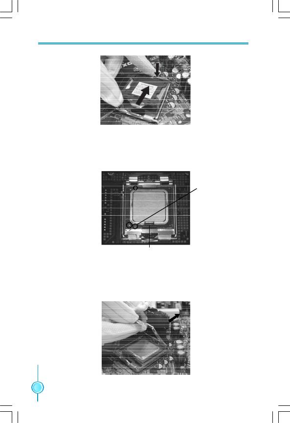
Below is the CPU socket illustration. Follow these procedures to install a CPU.
Load lever |
Load plate |
Protective cover
1. Use thumb and forefinger to hold the hook of the load lever and pull the lever down and away from socket to unlock it. Lift the load lever.
2. Push down the rear tab with your forefinger to bring the front end of the load plate up slightly. Open the load plate with thumb. Be careful not to touch the contacts.
 7
7
Chapter 2 Installation Instructions
3. Hold CPU with thumb and forefinger. Ensure fingers align to socket cutouts. Match the CPU triangle marker to Pin 1 position as shown below. The alignment key also provides the orientation directed function. Lower the CPU straight down without tilting or sliding the CPU in the socket.
Alignment
 Key
Key
Pin 1 position
Socket
Cutouts
4. After installing the CPU, remove the protective cover from load plate. The protective cover is used to protect the contacts of the socket. Do not discard the protective cover. Always replace the socket cover if the CPU is removed from the socket.
 8
8 

Chapter 2 Installation Instructions
5. Close the load plate, and slightly push down the tongue side.
6. Lower the lever and lock it to the load plate, then the CPU is locked completely.
 Note :
Excessive temperatures will severely damage the CPU and system. Therefore you should install the CPU cooling fan and make sure that it works normally at all times in order to prevent overheating and damage to the CPU. Please refer to your CPU fan user guide for correct installation.
Memory
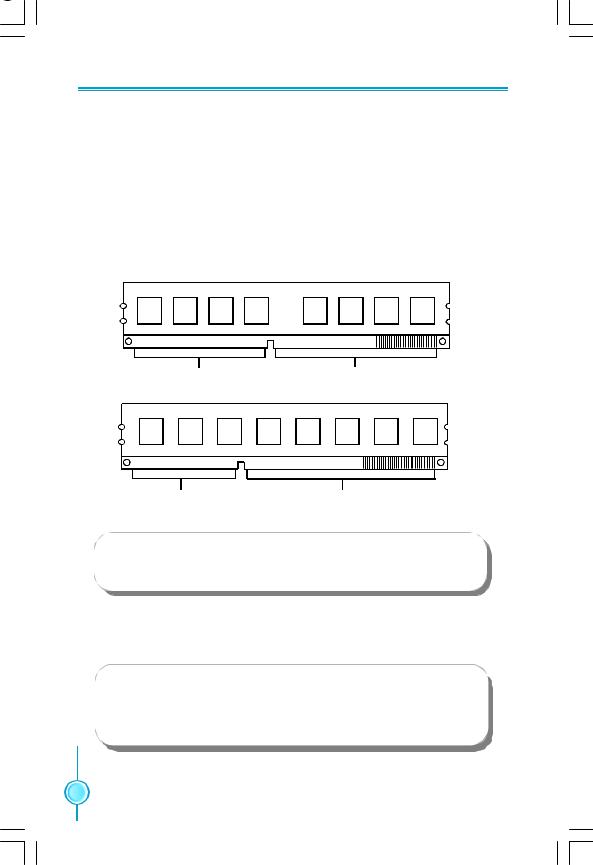
This motherboard includes four 240-pin slots with 1.8V for DDR2 and two 240pin slots with 1.5V For DDR3 . You must install at least one memory bank to ensure normal operation.
 9
9
Chapter 2 Installation Instructions
For the detailed memory support list on this motherboard, please visit the website: http://www.foxconnchannel.com
Installation of the Memory
1.There is only one gap near the center of the DIMM slot, and the memory module can be fixed in one direction only. Unlock a DIMM slot by pressing the module clips outward.
2.Align the memory module to the DIMM slot, and insert the module vertically into the DIMM slot.
|
|
|
|
|
|
|
|
|
|
|
|
|
|
|
|
|
|
|
|
|
|
|
|
|
|
|
|
|
|
|
|
|
|
|
|
|
|
|
|
|
|
|
|
|
|
|
|
|
|
|
|
|
|
|
|
|
|
|
|
|
|
|
|
|
|
|
|
|
|
|
|
|
|
|
|
|
|
|
|
|
|
|
|
|
|
|
|
|
|
|
|
|
|
|
|
|
|
|
|
|
|
|
|
|
|
|
|
|
|
|
|
|
|
|
|
|
|
|
|
|
|
|
|
|
|
|
|
|
|
|
|
|
|
|
|
|
|
|
|
|
|
|
|
|
|
|
|
|
|
|
|
|
|
|
|
|
|
|
|
|
|
|
|
|
|
|
|
|
|
|
|
|
|
|
|
|
|
|
|
|
|
|
|
|
|
|
|
|
|
|
|
|
|
|
|
|
|
|
|
|
|
|
|
|
|
|
|
|
|
|
|
|
|
|
|
|
|
|
|
|
|
|
|
|
|
|
|
|
|
|
|
|
|
|
|
|
|
|
|
|
|
|
|
|
|
|
|
|
|
|
|
|
|
|
|
|
|
|
|
|
|
|
|
|
|
|
|
|
|
|
|
|
|
|
|
|
|
|
|
|
|
|
|
|
|
|
112-Pin |
|
|
|
|
|
|
|
|
|
|
|
|
|
|
|
|
|
|
|
|
|
|
|
|
|
128-pin |
||||||||||||||||
DDR 2
|
|
|
|
|
|
|
|
|
|
|
|
|
|
|
|
|
|
|
|
|
|
|
|
|
|
|
|
|
|
|
|
|
|
|
|
|
|
|
|
|
|
|
|
|
|
|
|
|
|
|
|
|
|
|
|
|
|
|
|
|
|
|
|
|
|
|
|
|
|
|
|
|
|
|
|
|
|
|
|
|
|
|
|
|
|
|
|
|
|
|
|
|
|
|
|
|
|
|
|
|
|
|
|
|
|
|
|
|
|
|
|
|
|
|
|
|
|
|
|
|
|
|
|
|
|
|
|
|
|
|
|
|
|
|
|
|
|
|
|
|
|
|
|
|
|
|
|
|
|
|
|
|
|
|
|
|
|
|
|
|
|
|
|
|
|
|
|
|
|
|
|
|
|
|
|
|
|
|
|
|
|
|
|
|
|
|
|
|
|
|
|
|
|
|
|
|
|
|
|
|
|
|
|
|
|
|
|
|
|
|
|
|
|
|
|
|
|
|
|
|
|
|
|
|
|
|
|
|
|
|
|
|
|
|
|
|
|
|
|
|
|
|
|
|
|
|
|
|
|
|
|
|
|
|
|
|
|
|
|
|
|
|
|
|
|
|
|
|
96-Pin |
|
|
|
|
|
|
|
|
|
|
DDR 3 |
|
|
|
|
|
|
144-pin |
||||||||||||||||||||||||
 Warning:
Do not install DDR2 and DDR3 memory modules simultaneously on this motherboard. Doing so may result in damage to the motherboard and your system.
3. The plastic clips at both sides of the DIMM slot will lock automatically.
 Warning:
Be sure to unplug the AC power supply before adding or removing expansion cards or other system peripherals, especially the memory devices, otherwise your motherboard or the system memory might be seriously damaged.
 10
10 

Chapter 2 Installation Instructions
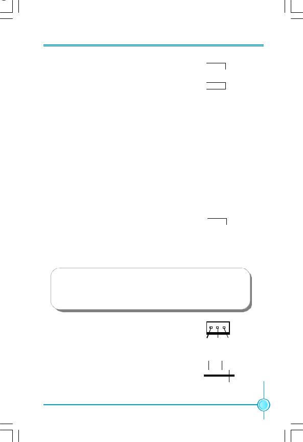
Power Supply
This motherboard uses an ATX power supply. In order to avoid damaging any devices, make sure that they have been installed properly prior to connecting the power supply.
|
|
+5V |
|
+5V_AUX |
+3.3V |
|||
|
+3.3V |
GND |
GND |
|
+12V |
|||
|
|
+12V |
||||||
24-pin ATX power connector: PWR1 |
+ 3. 3 V |
GND |
+5V PWROK |
|||||
|
|
|||||||
|
|
|
|
|
|
|
||
PWR1 is the ATX power supply connector. Make 1 |
|
|
|
|
|
12 |
||
sure that the power supply cable and pins are |
|
|
|
|
|
|
|
|
properly aligned with the connector on the |
13 |
|
|
|
|
|
24 |
|
motherboard. Firmly plug the power supply cable |
|
|
|
|
|
|||
+3.3V |
GND |
GND |
NC |
+5V |
||||
into the connector and make sure it is secure. |
||||||||
-12V |
GND |
GND |
|
+5V |
GND |
|||
|
|
PSON |
|
+5V |
|
|||
PWR1
8-pin ATX_12 V Power Connector: PWR2
The 8-pin ATX 12V power supply connects to PWR2 and provides power to the CPU.
5 1
12V
 GND
GND
12V
 GND
GND
12V
 GND
GND
12V
 GND
GND
8 4
PWR2
 Attention:
We recommend you use 24-pin power supply. If you want to use 20-pin power supply, you need to align the ATX power connector according to the following picture.
20-Pin Power |
24-Pin Power |
|
 11
11 

Chapter 2 Installation Instructions
Other Connectors
This motherboard includes connectors for FDD device, IDE device,Serial ATA devices, USB devices, IR module and others.
FDD Connector: FLOPPY
This motherboard includes a standard FDD connector, supporting 360K, 720K, 1.2M, 1.44M, and 2.88M FDDs.
IDE Connectors: PIDE
This connector support the provided Ultra DMA133/100/66 IDE hard disk ribbon cable and you can configure as a disk array through RAID controller.
 Attention:
If you install only one device on the IDE port such as a hard disk or a CD _ROM, please configure it as a master device.
Front Panel Connector: FP1
This motherboard includes one connector for connecting the front panel switch and LED indicators.
|
1 |
2 |
|||
HDD_LED |
+- |
|
|
|
-+ PLED |
|
|||||
RESET |
|
|
|
|
PWRSW |
|
|
|
|
||
NC 9 |
|
|
|
10 Empty |
|
Hard Disk LED Connector (HDD-LED) FP1
The connector connects to the case’s IDE indicator LED indicating the activity status of hard disks.
Reset Switch (RESET)
Attach the connector to the Reset switch on the front panel of the case; the system will restart when the switch is pressed.
Power LED Connector (PLED)
Attach the connector to the power LED on the front panel of the case. The Power LED indicates the system’s status. When the system is in S0 status, the LED is on. When the system is in S1 status, the LED is blink; When the system is in S3, S4, S5 status, the LED is off.
Power Switch Connector (PWRSW)
Attach the connector to the power button of the case. Pushing this switch allows the system to be turned on and off rather than using the power supply button.
 12
12 
Chapter 2 Installation Instructions
Audio Connector: F_AUDIO
1 2
PORT1_L
 AUD_GND
The audio connector supports HD audio standard. It provides two kinds of audio output choices: the Front Audio, the Rear Audio.
PORT1_R 
 PRESENCEJ PORT2_R
 SENSE1_RETURN
SENSE_SEND 
 Empty PORT2_L
 SENSE2_RETURN
9 10
F_AUDIO (HDA)
1394 Connector: F 1394(Optional)
The 1394 expansion cable can be connected to either the front (provided that the front panel of your chassis is equipped with the appropriate interface) or real panel of the chassis.
USB Connectors: F_USB1/2
In addition to the four USB ports on the rear panel,the series of motherboards also have two 10-pin connectors on board which may connect to the front panel USB cable to provide additional four USB ports.
1 2
TPA+
 TPAGND
 GND TPB+
 TPB- +12V
 +12V Empty
 GND
GND
910
F 1394
109
NC
 Empty GND
 GND D+
 D+
D+
D-
 D- VCC
 VCC
VCC
2 1
F_USB1/2
 Warning:
Before installing the USB cables, please pay attention to the marker of each individual USB cable; make sure to match them with each USB pin headers correctly, otherwise the USB ports will not work. Incorrect connection could also damage the motherboard.
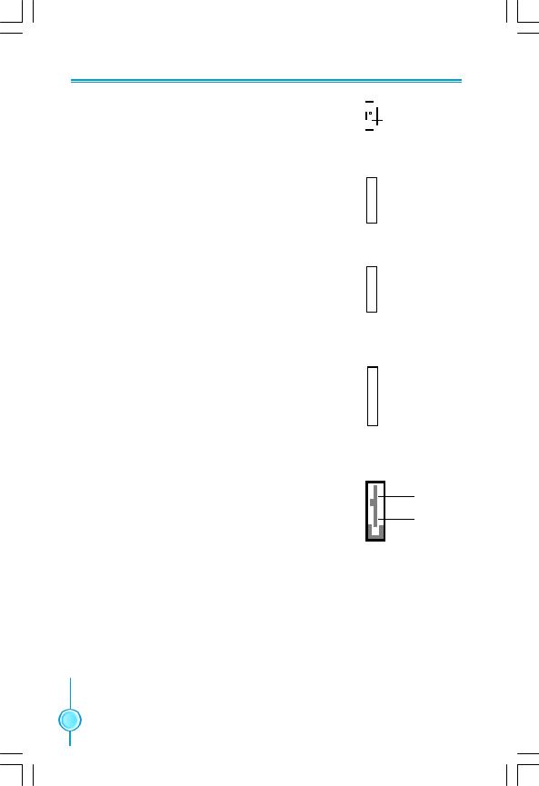
Fan Connectors: CPU_FAN,SYS_FAN,FAN1/ 2,NB _FAN
There are five fan connectors on this motherboard.The fan speed can be detected and viewed in “PC Health Status” section of the CMOS Setup. These fans will be automatically turned off after the system enters S3, S4 and S5 mode.
1
GND +12V SENSE
FAN1/2,NB-FAN
GND SENSE
1 
POWER CONTROL
CPU_FAN,SYS_FAN
13 
Chapter 2 Installation Instructions
Audio Connectors: CD_IN
CD_IN is the Sony standard CD audio connector, it can be connected to a CD-ROM drive through a CD audio cable.
Speaker Connector:SPEAKER(Optional)
The speaker connector is used to connect speaker of the chassis.
S/PDIF Out Connector:SPDIF-OUT1(Optional)
The SPDIF OUT1 connector is capable of providing digital audio to external speaker or compressed AC3 data to an external Dolby digital decoder.
IrDA Connector: IR
This header supports wireless transmitting and receiving device. Before using this founction,configure the settings of CMOS Setup.
Serial ATA II Connectors: SATA_1,SATA_2,
SATA_3,SATA_4,SATA_5,SATA_6
The Serial ATA II connector is used to connect the Serial ATA II device to the motherboard. These connectors support the thin Serial ATA II cables for Serial ATA II devices. The current Serial ATA II interface allows up to 300MB/s data transfer rate.

 CD_R
CD_R

 GND 1
GND 1 
 CD_L
CD_L
CD_IN
 SPKJ
SPKJ
 NC
NC
 EMPTY 1
  +5V
+5V
SPEAKER
1 +5V
+5V
 EMPTY
EMPTY
 SPDIF_OUT
 GND
GND
SPDIF_OUT1
 IRTX
IRTX
 GND
GND
 IRRX
IRRX
 Empty
Empty
1 +5V
+5V
IR
 GNDRX+
 RX-
RX-
 GND
GND
 TX- 1
TX- 1  GNDTX+
SATA_1/2/3/4/5/6
 14
14 
Chapter 2 Installation Instructions
Expansion Slots
This motherboard includes three 32-bit master PCI slots,two PCI Express x1 slots and two PCI Express x16 slots.
For the detailed PCI Express cards support list on this motherboard, please visit the website: http://www.foxconnchannel.com
PCI Slot
The expansion cards can be installed in the three PCI slots. PCI slots support cards such as a LAN card, USB card, SCSI card and other cards that comply with PCI specifications.
PCI Express x1 Slot
This motherboard has two PCI Express x1 slots designed to accommodate less bandwidth-intensive cards, such as a modem or LAN card.The PCI Express x1 slot offering 250MB/s(500MB/s concurrent) of bandwidth.
PCI Express x16 Slot
This motherboard has two PCI Express x16 slots that reserved for graphics or video cards. The PCI Express x16 slots offering 4GB/s (8GB/s concurrent) of bandwidth.
Installing an expansion card
1.Before installing the expansion card, read carefully the documentation that came with it and make the necessary hardware settings for the card.
2.Make sure to unplug the power cord before adding or removing any expansion cards,Remove the bracket opposite the slot that you intend to use.
3.Align the card connector with the slot and press firmly until the card is completely seated in the slot.
4.Secure the card to the chassis with the screw you removed earlier.
 Warning:
If a performance graphics card was installed into x16 PCI Express slot,24 pin power supply was recommended.
 15
15 
 Loading...