


6100K8MA-RS

This manual is the intellectual property of Foxconn Inc. Although the
information in this manual may be changed or modified at any time,
Foxconn does not obligate itself to inform the user of these changes.
Statement:
All trademarks are the property of their respective owners.
User’s Manual V1.1 for 6150/6100K8MA series motherboard.
Symbol description:
Note: refers to important information that can help you to use motherboard
better.
Attention: indicates that it may damage hardware or cause data loss,
and tells you how to avoid such problems.
Warning: means that a potential risk of property damage or physical
injury exists.
More information:
If you want more information about our products, please visit the following
website: http://www.foxconnchannel.com
Version:
Trademark:
Declaration of conformity
HON HAI PRECISION INDUSTRY COMPANY LTD
66 , CHUNG SHAN RD., TU-CHENG INDUSTRIAL DISTRICT,
TAIPEI HSIEN, TAIWAN, R.O.C.
declares that the product
Motherboard
6150/6100K8MA
is in conformity with
(reference to the specification under which conformity is declared in
accordance with 89/336 EEC-EMC Directive)
þ EN 55022: 1998/A2: 2003Limits and methods of measurements of radio disturbance
characteristics of information technology equipment
þ EN 61000-3-2: 2000 Electromagnetic compatibility (EMC)
Part 3: Limits
Section 2: Limits for harmonic current emissions
(equipment input current <= 16A per phase)
þ EN 61000-3-3/A1:2001 Electromagnetic compatibility (EMC)
Part 3: Limits
Section 2: Limits of voltage fluctuations and flicker in low-voltage
supply systems for equipment with rated current <= 16A
þ EN 55024: 1998/A2:2003Information technology equipment-Immunity characteristics limits
and methods of measurement
Signature : Place / Date : TAIPEI/2005
Printed Name : James Liang Position/ Title : Assistant President

Declaration of conformity
Trade Name: WinFast
Model Name: 6150/6100K8MA
Responsible Party: PCE Industry Inc.
Address: 458 E. Lambert Rd.
Fullerton, CA 92835
Telephone: 714-738-8868
Facsimile: 714-738-8838
Equipment Classification: FCC Class B Subassembly
Type of Product: Motherboard
Manufacturer: HON HAI PRECISION INDUSTRY
COMPANY LTD
Address: 66 , CHUNG SHAN RD., TU-CHENG
INDUSTRIAL DISTRICT, TAIPEI HSIEN,
TAIWAN, R.O.C.
Supplementary Information:
This device complies with Part 15 of the FCC Rules. Operation is subject to the
following two conditions : (1) this device may not cause harmful interference, and (2)
this device must accept any interference received, including interference that may
cause undesired operation.
Tested to comply with FCC standards.
Signature : Date : 2005

Main Features.............................................................................................2
Motherboard Layout...................................................................................5
Rear Panel Connectors...............................................................................6
Installation Instructions
CPU............................................................................................................9
Memory....................................................................................................12
Power Supply...........................................................................................14
Other Connectors.....................................................................................15
Expansion Slots........................................................................................20
Jumpers...................................................................................................22
BIOS Description
Enter BIOS Setup......................................................................................25
Main Menu................................................................................................25
Standard CMOS Features.........................................................................27
BIOS Features..........................................................................................30
Advanced BIOS Features.........................................................................32
Advanced Chipset Features.....................................................................35
Integrated Peripherals...............................................................................38
Power Management Setup........................................................................43
PnP/PCI Configurations.............................................................................46
PC Health Status.......................................................................................47
Load Fail-Safe/Optimized Defaults............................................................48
Set Supervisor/User Password....................................................................48
Save & Exit Setup.....................................................................................49
Exit Without Saving...................................................................................49
Table of Contents
Chapter
1
Chapter
2
Chapter
3
Product Introduction

Driver CD Introduction
Utility CD content......................................................................................51
Start to install drivers................................................................................52
Directions for Bundled Software
SuperStep................................................................................................54
SuperUpdate............................................................................................57
SuperLogo...............................................................................................62
nTune.......................................................................................................64
Special BIOS Functions
SuperBoot................................................................................................73
SuperBIOS-Protect...................................................................................74
SuperRecovery........................................................................................75
Appendix
Using 8-channel Audio (optional)..............................................................85
Table of Contents
4
Chapter
5
Chapter
6
Chapter
1.Attach the CPU and heatsink using silica gel to ensure full contact.
2.It is suggested to select high-quality, certified fans in order to avoid
damage to the motherboard and CPU due to high temperature.
3.Never turn on the machine if the CPU fan is not properly installed.
4.Ensure that the DC power supply is turned off before inserting or re
moving expansion cards or other peripherals, especially when you
insert or remove a memory module. Failure to switch off the DC power
supply may result in serious damage to your system or memory
module.
Warning:
We cannot guarantee that your system will operate normally while
overclocked. Normal operation depends on the overclock capacity of
your device.
Warning:
Attention:
Since BIOS programs are upgraded from time to time, the BIOS de-
scription in this manual is just for reference. We do not guarantee that
the content of this manual will remain consistent with the actual BIOS
version at any given time in the future.
Attention:
The pictures of objects used in this manual are just for your reference.
Please refer to the physical motherboard.

This manual is suitable for motherboard of 6150/6100K8MA
series. Each motherboard is carefully designed for the PC user
who wants diverse features.
-L with onboard 10/100M LAN
-K with onboard Gigabit LAN
-6 with 6-channel audio
-8 with 8-channel audio
-E with 1394
-S with SATA
-R with RAID
You can find PPID label on the motherboard. It indicates the
functions that the motherboard has.
For example:
On the black mark of the PPID label, it means the motherboard
supports 6-channel Audio (-6), 1394 port (-E), onboard 10/100M
LAN (-L), SATA function (-S).

Chapter
Thank you for buying WinFast 6150/6100K8MA series
motherboard. This series of motherboard is one of our new
products, and offers superior performance, reliability and
quality, at a reasonable price. This motherboard adopts the
advanced NVIDIA
®
GeForce
TM
6150 + nForce
TM
430 /
GeForce
TM
6100+nForce
TM
410 chipset, providing users a
computer platform with a high integration-compatibility-per-
formance price ratio.
This chapter includes the following information:
v Main Features
v Motherboard Layout
v Rear Panel Connectors
1
1

Chapter 1 Product Introduction
2
Main Features
Size:
l mATX form factor of 9.6” x 9.6”
Microprocessor:
l Supports Socket 939 for AMD Athlon
TM
64 x2 Dual core/Athlon
TM
64FX/Athlon
TM
64/Sempron processors
HyperTransport Technology:
l 16 x 16 link running at 1GHz for extremely high throughput (8.0GB/sec)
l Differential lines with low voltage swings
Chipset:
l 6150K8MA Chipset: NVIDIA® GeForce
TM
6150+nForce
TM
430
l 6100K8MA Chipset: NVIDIA® GeForce
TM
6100+nForce
TM
410
System Memory
l Four 184-pin DDR DIMM slots
l Supports DDR 266/333/400 memory
l Supports 128/256/512/1024Mb technology up to 4GB
USB 2.0 Port
l Supports hot-plug
l Eight USB 2.0 ports (four rear panel ports, two onboard USB connectors
providing four extra ports)
l Supports USB 2.0 protocol up to 480Mbps transmission rate
Onboard Serial ATA II (optional)
l nForce 410 supports two Serial ATA II connectors, nForce 430 supports four
Serial ATA II connectors.
l Up to 300Mps transfer rates
NVIDIA RAID Technology
l nForce 410 supports RAID 0 and RAID 1, nForce 430 supports RAID 0,RAID 1,
RAID 0+1,RAID 5

3
Chapter 1 Product Introduction
Onboard 1394 (optional)
l Supports hot-plug
l With rate of transmission at 400Mbps
l Self-configured addressing
Onboard LAN (-L/-K) (optional)
l Supports10/100/1000 (-L/-K) Mbps Ethernet
l LAN interface built-in on board
Note: The shielded LAN Cables are recommended.
Onboard Audio (-6) (optional)
l AC’97 2.3 Specification Compliant
l Supports SPDIF output
l Onboard Line-in jack, Microphone jack, Line-out jack
l Supports 6-channel audio
Onboard Audio (-8) (optional)
l Supports 8-channel audio
l Supports SPDIF output
l Supports Universal Audio Jack (UAJ)
l AC’97 2.3 Specification Compliant
Onboard Graphics
l Supports integrated VGA display functions
BIOS
l Licensed advanced AWARD (Phoenix) BIOS, supports flash ROM, Plug-and-
Play
l Supports IDE HDD, CD-ROM, SCSI HDD or USB device boot up
Green Function
l Supports ACPI (Advanced Configuration and Power Interface)
l Supports S0 (normal), S1 (power on suspend), S3 (suspend to RAM), S4
(suspend to disk-depends on OS), and S5 (soft-off) ACPI state
PCI Express x16 support
l Supports 4 GB/sec (8GB/sec concurrent) bandwidth
l Low power consumption and power management features

Chapter 1 Product Introduction
4
Expansion Slots
l Three PCI slots
l One PCI Express x16 Graphics slot
Onboard TV OUT (optional)
l Full NVIDIA nView
TM
multi-display technology capability,with independent dis-
play controllers for the CRT/TV interface
Advanced Features
l PCI 2.3 Specification Compliant
l Supports PC Health function (capable of monitoring system voltage, CPU/
system temperature, and fan speed)
5
Chapter 1 Product Introduction
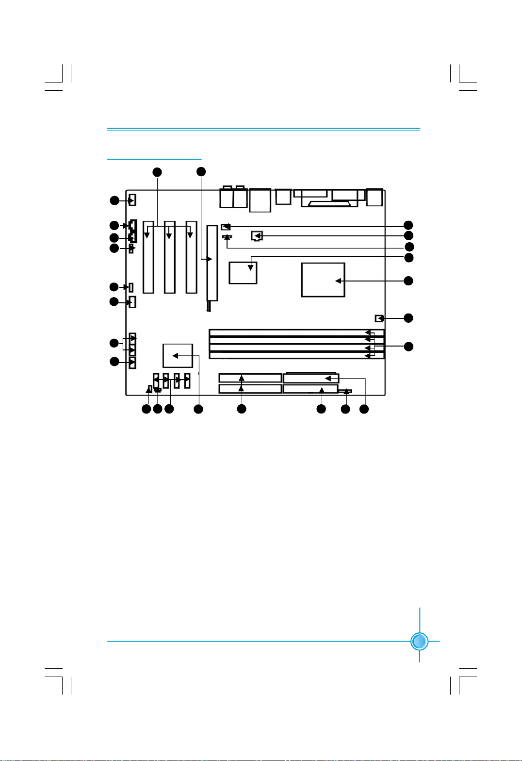
1. Front Audio Connector
2. CD_IN Connector
3. AUX_IN Connector (optional)
4. SPDIF_OUT Connector
5.Speaker Connector
6. Front 1394 Connector (optional)
7. Front USB Connectors
8. Front Panel Connector
9.Clear CMOS Jumper
10. Chassis Intruder Connector
11. SATA II Connectors (optional)
12. South Bridge: NVIDIA nForce 430
/nForce 410
13. IDE Connectors
14. Floppy Drive Connector
15. IrDA Connector
16. 24-pin Power Connector
17. DDR DIMM Slots
18. CPU_FAN Connector
19. CPU Socket
20. North Bridge: NVIDIA GeForce 6150/
GeForce 6100
21. TV OUT Connector(optional)
22.4-pin 12V Power Connector
23. System FAN Connector
24. PCI Express x16 Slot
25. PCI Slots
Motherboard Layout
18
3
2
19
Note: The above motherboard layout is provided for reference only; please
refer to the physical motherboard.
1
4
5
6
7
8
11
9
10
12
13
15 16
14
17
20
21
22
23
24
25
Chapter 1 Product Introduction
6
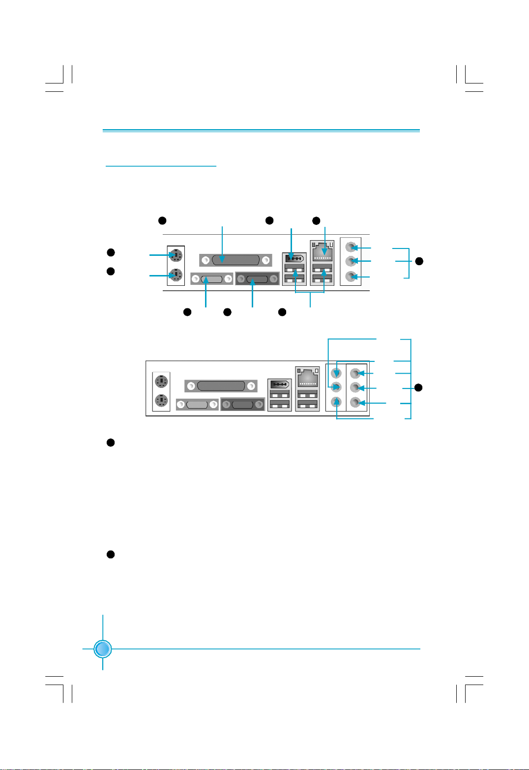
Rear Panel Connectors
This motherboard provides the ports as below:
Line in, Line out, Microphone Jacks (for -6 models)
When using a 2-channel sound source, the Line-out jack is used to connect to
speaker or headphone; the Line-in jack connects to an external CD player, tape
player or other audio device. The Microphone jack is used to connect to the
microphone.
When using a 6-channel sound source, connect the front speaker to the green
audio output; connect the surround sound speaker to the blue audio output;
connect the center speaker/subwoofer to the red Microphone output.
Line in, Line out, Microphone, Rear, LEF/CEN, Side Jacks (for -8 models)
When using an 8-channel sound source, connect the front speaker to the green
audio output; connect the rear sound speaker to the black audio output; con-
nect the center speaker/subwoofer(LFE/CEN) to the orange audio output; con-
nect the side sound speaker to the blue audio output.
9
10
-6 models (optional)
-8 models (optional)
VGA Port
(optional)
PS/2 Mouse
Connector
PS/2 Keyboard
Connector
1
2
5
1394 Port
(optional)
LAN Port (optional)
8
9
Parallel Port (Printer Port)
4 6
Serial Port
(COM1)
3
3
USB 2.0 Ports7
Line-in
Line-out
Microphone
10
Rear
Line-out
Microphone
Line-in
LFE/CEN
Side
7
Chapter 1 Product Introduction
This chapter introduces the hardware installation process,
including the installation of the CPU and memory. It also
addresses the connection of your power supply, connection
of hard drive and floppy drive data cables, and setting up
various other feature of the motherboard. Caution should be
exercised during the installation process. Please refer to
the motherboard layout prior to any installation and read the
contents in this chapter carefully.
This chapter includes the following information:
v CPU
v Memory
v Power Supply
v Other Connectors
v Expansion Slots
v Jumpers
Chapter
2
2
8
Chapter 2 Installation Instructions
Notes:
Take note of the following precautions before you install components
or change settings.
1. Use a grounded wrist strap or touch a safely grounded object, such
as an attached power supply, before handling components to avoid
damaging them due to static electricity.
2. Unplug the power cord before opening your chassis or touching any
components.
3. Hold components by their edges to avoid touching any exposed
integrated circuits (ICs).
4. Whenever you uninstall a component, place it on a grounded anti-
static pad or into the antistatic bag that it came in.
9
Chapter 2 Installation Instructions
CPU
This motherboard supports Socket 939 for Athlon
TM
64 x2 Dual core/ Athlon
TM
64FX/Athlon
TM
64/Sempron processors and Hyper Transport
TM
Technology.
For the detailed CPU vendor list qualified on this motherboard, please visit
the website: http://www.foxconnchannel.com
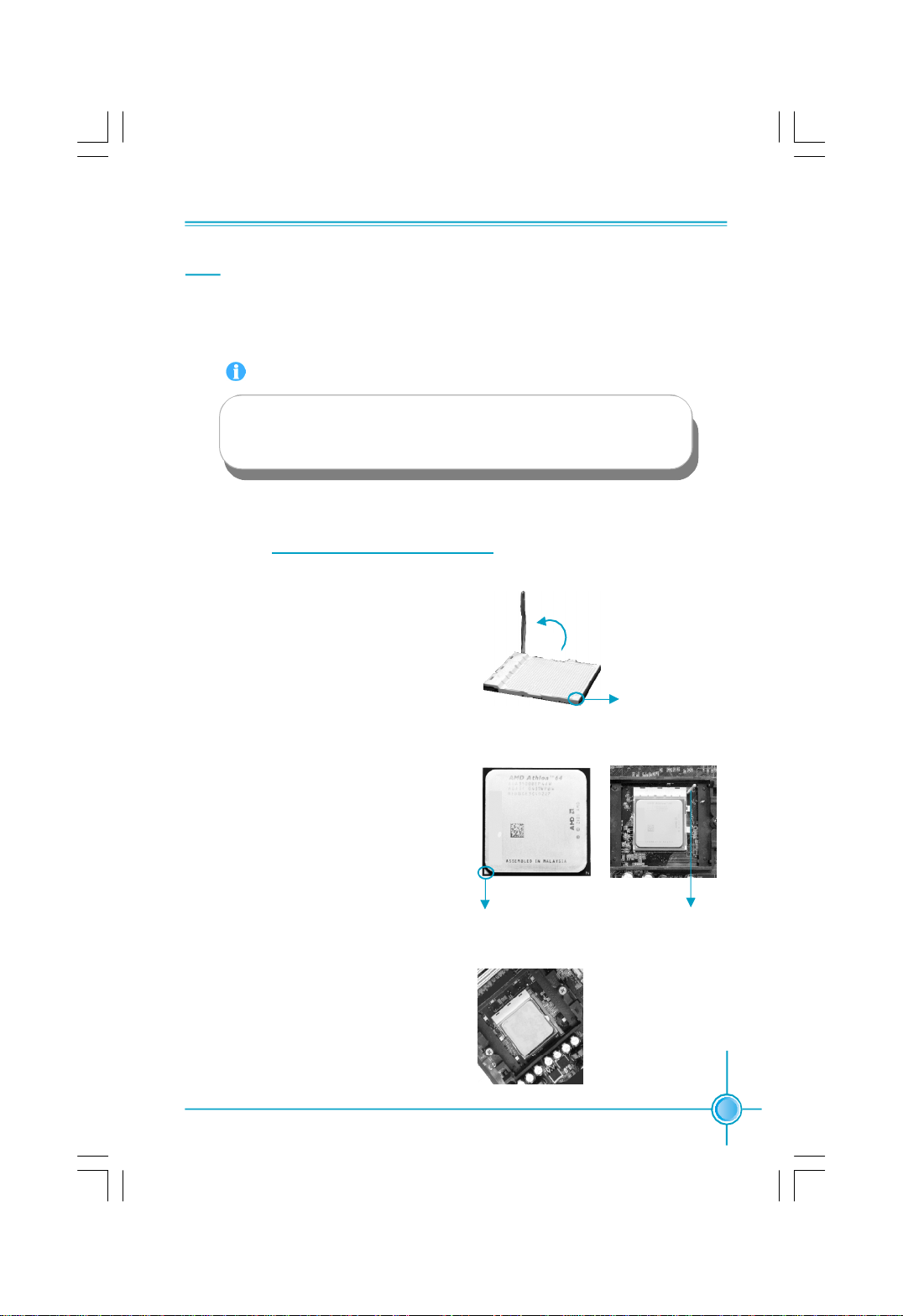
Installation of CPU
Follow these steps to install the CPU.
1.Unlock the socket by pressing the le-
ver sideways, then lift it up to a 90
o
angle.
2.Align the cut edge to the gap in the base
of the socket. Carefully insert the CPU
into the socket until it fits in place.
3.When the CPU is in place, press it
firmly on the socket while you push
down the socket lever to secure the
CPU. The lever clicks on the side tab
to indicate that it is locked.
Push down the socket
lever to secure the CPU.
Cut edge
90
o
Gap in the base
Attention:
The CPU pins must be properly aligned with the holes in the
socket, otherwise the CPU may be damaged.

10
Chapter 2 Installation Instructions
1. Locate the CPU retention mecha-
nism base (surrounds the CPU
socket).
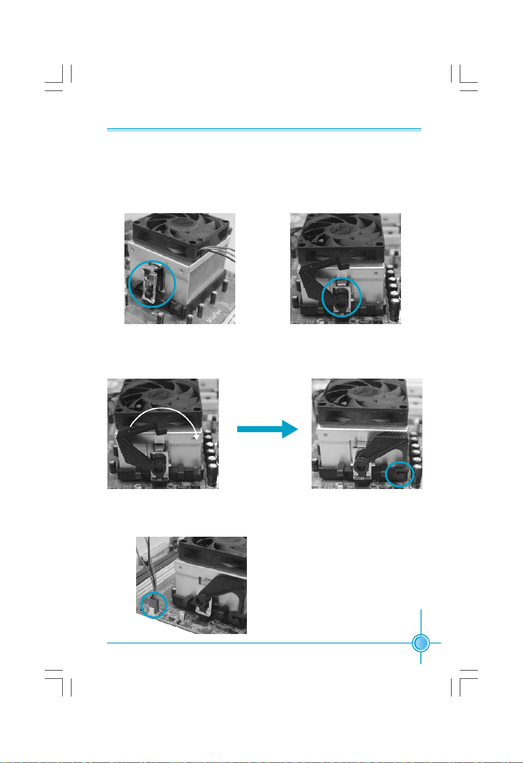
Installation of CPU Fan
New technology allows processors to run at higher and higher frequencies.
To avoid problems arising from high-speed operation, for example,
overheating, you need to install the proper fan. The following procedure is
provided for reference only, please refer to your CPU fan user guide for the
actual procedure.
2.If required, apply a light coating of
silica gel to the top of the CPU.
NOTE: The CPU heatsink may have
a pre-applied thermal compound. In
that case, the silica gel is not required.
CPU Fan
CPU Heatsink
CPU Retention Mechanism
CPU Retention Bracket
CPU Retention Lock
11
Chapter 2 Installation Instructions
5.Push down the retention bracket lock on the retention mechanism to secure
the heatsink and fan to module base.
6.Connect the fan’s power cable to the appropriate 3-pin terminal on the
motherboard.
4.Align the other end of the reten-
tion bracket to fasten the cooling
set on the top of the retention
mechanism.
3. Place the cooling set onto the re-
tention mechanism. Attach one end
of the retention bracket to retention
mechanism.
12
Chapter 2 Installation Instructions
Memory
This motherboard includes four 184-pin slots with 266/333/400 MHz Dual Chan-
nel DDR DRAM interface, You must install at least one memory module to
ensure normal operation. If you install more than two modules, they must be
the same speed. Mixing memory modules from different manufactures are not
recommended.
For the latest memory modules support list, please visit the website:
h
ttp://www.foxconnchannel.com
Installation of DDR Memory
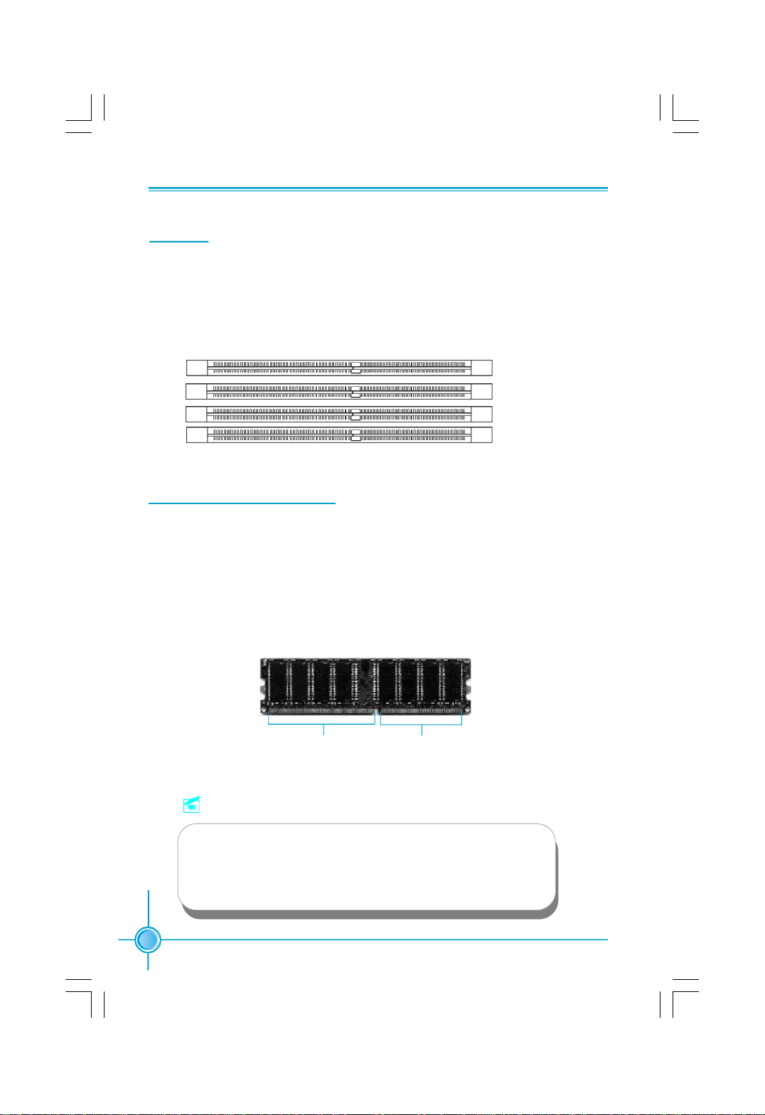
1.There is only one gap in the center of the DIMM slot, and the memory module
can be fixed in one direction only.
2.Align the memory module to the DIMM slot, and insert the module
vertically into the DIMM slot.
3.The plastic clips at both sides of the DIMM slot will lock automatically.
104 Pins 80 Pins
DIMM1
DIMM2
DIMM3
DIMM4
Note:
Be sure to unplug the AC power supply before adding or re-
moving expansion cards or other system peripherals, espe-
cially the memory devices, otherwise your motherboard or the
system memory might be seriously damaged.

13
Chapter 2 Installation Instructions
Recommended Memory Configurations
The following table list is the recommended memory configurations. Please in-
stall the memory according to the list.
Note:
Installing DDR DIMMs other than the recommended configu-
rations may cause memory sizing error or system boot failure.
Mode DIMM1 DIMM2 DIMM3 DIMM4
Populated
Signal-channel Populated
Populated Populated
Populated Populated
Dual-channel Populated Populated
Populated Populated Populated Populated
14
Chapter 2 Installation Instructions
Power Supply
This motherboard uses an ATX power supply. In order to avoid damaging any
devices, make sure that they have been installed properly prior to connecting
the power supply.
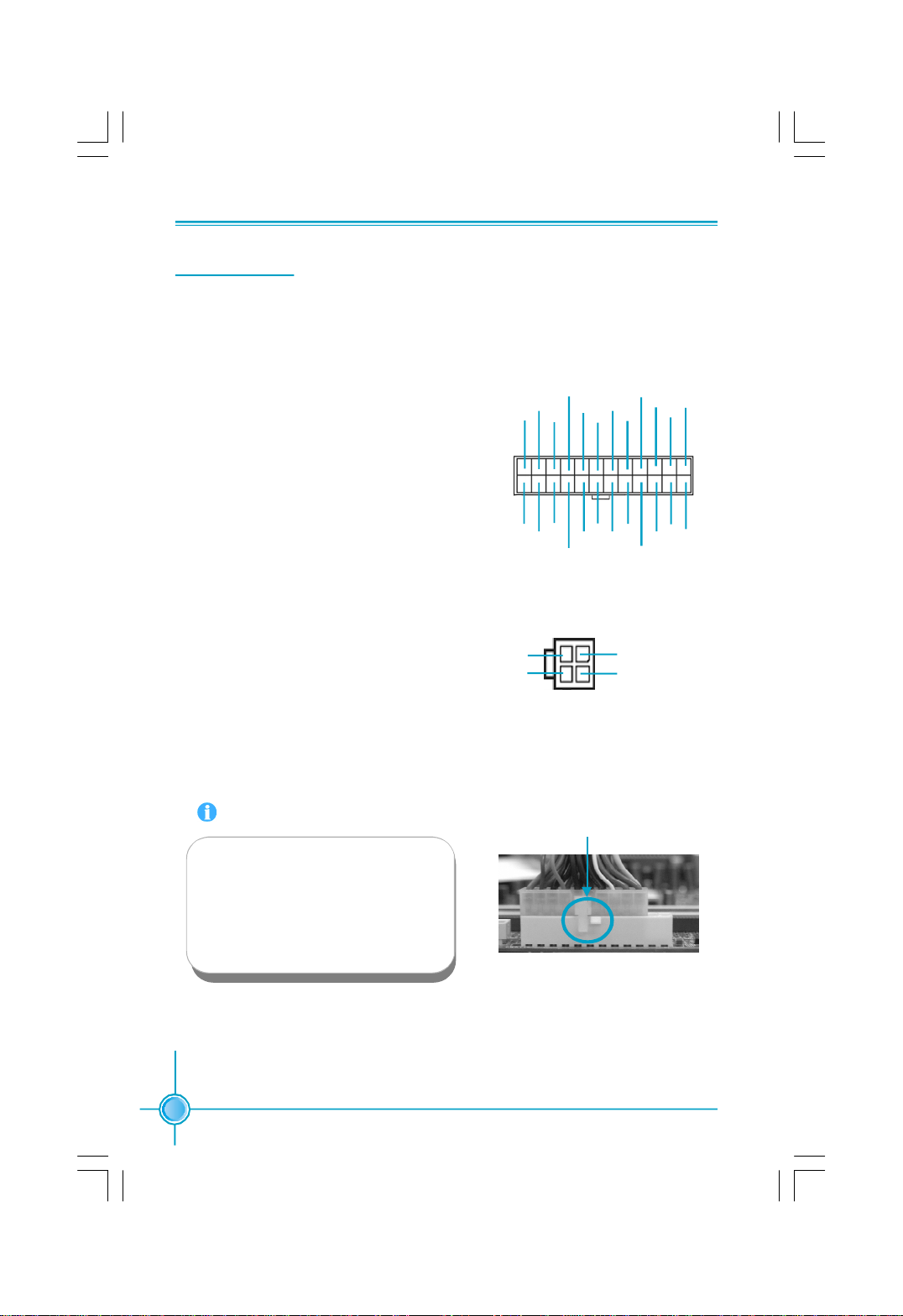
ATX Power Connector: PWR1
PWR1 is the ATX power supply connector.
Make sure that the power supply cable
and pins are properly aligned with the
connector on the motherboard. Firmly
plug the power supply cable into the con-
nector and make sure it is secure.
ATX 12V Power Connector: PWR2
The 4 pin ATX 12V power supply connects
to PWR2 and provides power to the CPU.
Attention:
We strongly recommend you use
24-pin power supply. If you want to
use 20-pin power supply, you need
to align the ATX power connector
according to the right picture.
4-pin ATX_12V power connector
12V
GND
12V
3 1
4
2
GND
24-pin ATX power connector
2413
+3.3V
-12V
NC
+5V
GND
GND
GND
PSON
+5V
+3.3V
GND
+12V
GND
+5V_AUX
+3.3V
+5V
+12V
GND
+5V
+3.3V
GND
GND
+5V
12
PWROK
1
15
Chapter 2 Installation Instructions
This motherboard includes connectors for FDD devices, IDE HDD devices,
SATA devices, USB devices, 1394 devices, IR module, CPU fan, system fan, and
others.
FLOPPY
This motherboard includes a standard FLOPPY interface, supporting 360 K, 720 K,
1.2 M, 1.44 M, and 2.88 M FDDs.
IDE Connectors: PIDE & SIDE
These connectors support the Ultra DMA133/100/66 IDE hard disk ribbon cable.
Connect the cable’s blue connector to the primary (recommended) or second-
ary IDE connector, then connect the gray connector to the slave device (hard
disk drive) and the black connector to the master device. If you install two hard
disks, you must configure the second drive as a slave device by setting its
jumper accordingly. Refer to the hard disk documentation for the jumper settings.
Other Connectors
Attention:
Ribbon cables are directional, therefore, make sure to always con-
nect with the cable on the same side as pin 1 of the PIDE/SIDE or
FDD connector on the motherboard.
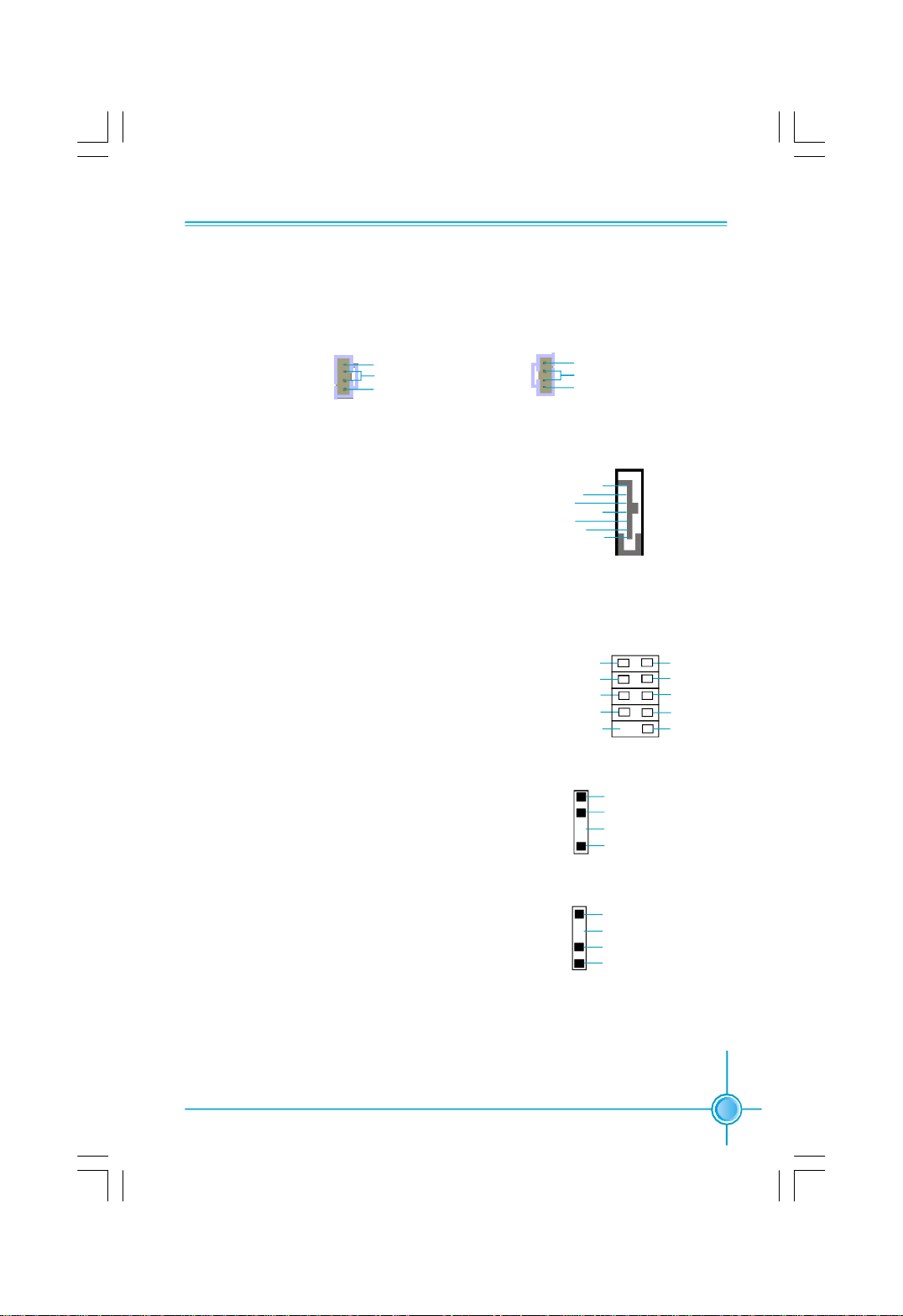
Front Panel Connector: FP1
This motherboard includes one connector for con-
necting the front panel switch and LED indicator.
NC
HDD_LED
RESET
PLED
PWRBTN#
+
-
9 10
1 2
FPFP1!
+
-
Empty
Hard Disk LED Connector (HDD_LED)
Attach the connector to the HDD_LED on the front panel of the case; the LED will
flash while the HDD is in operation.
Reset Switch (RESET)
Attach the connector to the Reset switch on the front panel of the case; the
system will restart when the switch is pressed.
16
Chapter 2 Installation Instructions
USB Connectors: F_USB 1, F_USB 2
Besides four USB ports on the rear panel, the series of motherboards also
have two 10-pin connectors on board which may connect to the front panel USB
cable to provide additional four USB ports.
IrDA Connector: IR
The IrDA infrared transmission allows your com-
puter to send and receive data via an infrared ray.
The relevant parameters for the BIOS Integrated
Peripherals should be set prior to using this
function.
IR
+5V
GND
IRRX
IRTX
Empty
1
F_USB1
10 9
VCC
D4+
D4-
Empty
GND
NC
VCC
GND
D5+
2 1
F_USB2
10 9
D7-
VCC
D6+
D6-
Empty
GND
NC
VCC
GND
D7+
2 1
D5-
Power LED Connector (PLED)
Attach the connector to the Power LED on the front panel of the case. The Power
LED indicates the power supply status. When the system is in S0 status, the
green LED is on. When the system is in S1 status, the green LED is blink. When
the system is in S3, the yellow LED is blink. When the system is in S4, S5 status,
the LED is off.
Power Switch Connector (PWRBTN#)
Attach the connector to the power button of the case. Pushing this switch allows
the system to be turned on and off rather than using the power supply button.
Fan Connectors: CPU_FAN, SYS FAN
There are two fan connectors on this motherboard.
SYS FAN
SENSE
+12V
GND
1
CPU_FAN
SENSE
+12V
GND1
17
Chapter 2 Installation Instructions
Audio Connector: CD_IN, AUX_IN (optional)
CD_IN, AUX_IN are Sony standard CD audio connectors, to receive audio input
from the CD-ROM, attach the audio connector to the CD_IN,AUX_IN audio con-
nectors on the motherboard.
The Serial ATA II connectors are used to con-
nect the S-ATA II devices to the motherboard.
These connectors support the thin Serial ATA II
cables for primary internal storage devices. The
current Serial ATA II interface allows up to 300MB/
s data transfer rate.
Serail ATA II Connectors: SATA_1, SATA_2,
SATA_3(optional),SATA_4(optional)
1394 Connector: F_1394 (optional)
The 1394 expansion cable can be connected to
either the front (provided that the front panel of
your chassis is equipped with the appropriate
interface) or the rear panel of the chassis.
CD_IN
CD_R
GND
CD_L
1
AUX_IN
AUX_R
GND
AUX_L
1
Empty
F_1394
TPB+
TPA+
+12V
GND
TPB-
+12V
GND
GND
TPA-
1 2
9 10
SATA_1/SATA_2/
SATA_3/SATA_4
GND
GND
GND
TX+
TX-
RX+
RX-
1
Speaker Connector
The speaker connector is used to connect
speaker of the chassis.
1 SPK(Pull high)
SPKJ
EMPTY
NC
SPEAKER
SPDIF Out Connector: SPDIF_OUT
The SPDIF out connector is capable of provid-
ing digital audio to external speakers or com-
pressed AC3 data to an external Dolby digital
decoder.
Note:The empty pin of SPDIF cable should be
aligned to empty pin of SPDIF out connector.
SPDIF_OUT
5V
SPDIF-OUT
GND
EMPTY
1

18
Chapter 2 Installation Instructions
Chassis Intruder Connector: INTR
The connector connects to the chassis security
switch on the case. The system can detect the
chassis intrusion through the status of this
connector. If the connector has been closed
once, the system will send a message. To uti-
lize this function, set “ICase Open Warning” to
“Enabled” in the “Power Management Setup”
section of the CMOS Setup. Save and exit, then
boot the operating system once to make sure
this function takes effect.
INTR
1
2
INTRUDERJ
GND
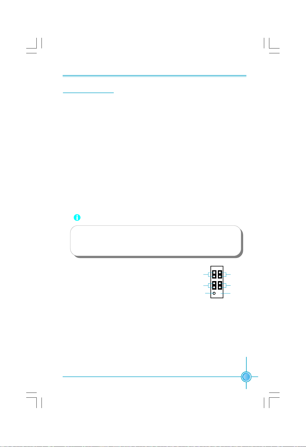
Front Audio Connector: F_AUDIO
The audio port includes two parts – the Front
Audio and Rear Audio. Their priority is se-
quenced from high to low (Front Audio to Rear
Audio). If headphones are plugged into the front
panel of the chassis (using the Front Audio),
then the Line Out (Rear Audio) on the rear panel
will not work. If you do not want to use the Front
Audio, pin 5 and 6, pin 9 and 10 must be short,
and then the signal will be sent to the rear au-
dio port.
F_AUDIO
MIC_GND
MIC_IN
+5VA
MIC_PWR
AUD_RET_R
AUD_OUT_R
EMPTY
AUD_OUT_L
AUD_RET_L
1 2
9 10
NC
TV OUT Connector: TV_OUT (optional)
This connector is for TV out function. Using this
function, you can use a TV or projector as display
device. The following steps are provided refer-
ence only.
1
S_VIDIO_C
S_VIDIO_Y
TV _OUT
GND
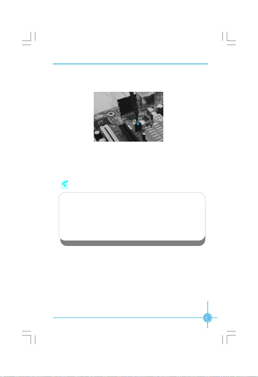
Step 1. Install TV out cable to a slot opening at the back of the system chassis (As
figure 1).
Note:
The triangle direction on the 3-pin connector should be aligned
to 1st pin of the TV out connector on the motherboard.
A
B
Figure 1
19
Chapter 2 Installation Instructions
Step 2. Connect the 3-pin connector (A) of the TV out cable to TV out connector (As
figure 2).
Step 3. Plug the display cable into your S-video port of the TV out cable (B).
Then you can use this function.
Note:
1. When VGA port and TV out port are both connected to display devices,
the system will define VGA port as default setting. If you want to change
the display priority, please go to Display properties --> Setting --> Ad-
vanced --> C51 --> nView display setting to select the desired display
device.
2. When you use TV as display device, please make sure your resolution
has been set as 800 x 600 60Hz or 640 x 480 60Hz.
3. Windows XP or Windows 2000 is strongly recommended.
Figure 2

20
Chapter 2 Installation Instructions
Expansion Slots
This motherboard includes three32-bit Master PCI bus slots, and one PCI Ex-
press x16 slot.
PCI Slots
The expansion card can be installed in the PCI slot. When you install or take out
such card, you must make sure that the power plug has been pulled out.
Please read carefully the instructions provided for such card, and install and set
the necessary hardware and software for such card, such as the jumper or
BIOS setup.
PCI Express Slots
PCI Express will offer the following design advantages over the PCI and AGP
interface:
-Compatible with existing PCI drivers and software and Operating Systems.
-High Bandwidth per Pin. Low overhead. Low latency.
-PCI Express supports a raw bit-rate of 2.5 Gb/s on the data pins. This
results in a real bandwidth per pair of 250 MB/s.
-A point to point connection, allows each device to have a dedicated connec-
tion without sharing bandwidth.
-Ability to comprehend different data structure.
-Low power consumption and power management features.
PCI Express will take two forms, x16 and x1 PCI Express slots. Whereas the x16
slot is reserved for graphic/video cards, the x1 slots are designed to accommo-
date less bandwidth-intensive cards, such as a modem or LAN card.
The difference in bandwidth between the PCI Express x16 and PCI Express x1
slots are not able to be sure, with the PCI Express x16 slot pushing 4GB/sec
(8GB/sec concurrent) of bandwidth, and the PCI Express x1 slot offering 250MB/
sec.
If a performance graphics card was installed into x16 PCI
Express slot, 2X12 pin power supply was strongly recommended.
Warning:

21
Chapter 2 Installation Instructions
Installing an expansion card
1.Before installing the expansion card, read the documentation that came with
it and make the necessary hardware settings for the card.
2.Make sure to unplug the power cord before adding or removing expansion
cards.
3.Align the card connector with the slot and press firmly until the card is
completely seated on the slot.
4.Secure the card to the chassis with the screw you removed earlier.
For more details on PCI Express x 16 graphics card support list qualified on this
motherboard, please visit the website: h
ttp://www.foxconnchannel.com

22
Chapter 2 Installation Instructions
Jumpers
Users can change the jumper settings on this motherboard if necessary. This
section explains how to use the various functions of this motherboard by chang-
ing the jumper settings. Users should read the following contents carefully prior
to modifying any jumper settings.
Description of Jumpers
1.For the jumpers on this motherboard, pin 1 can be identified by the silk-
screen printed “ ” next to it. However, in this manual, pin 1 is simply
labeled as “1”.
2.The following table provides some explanations of the jumper pin settings.
Users should refer to the table while adjusting jumper settings.
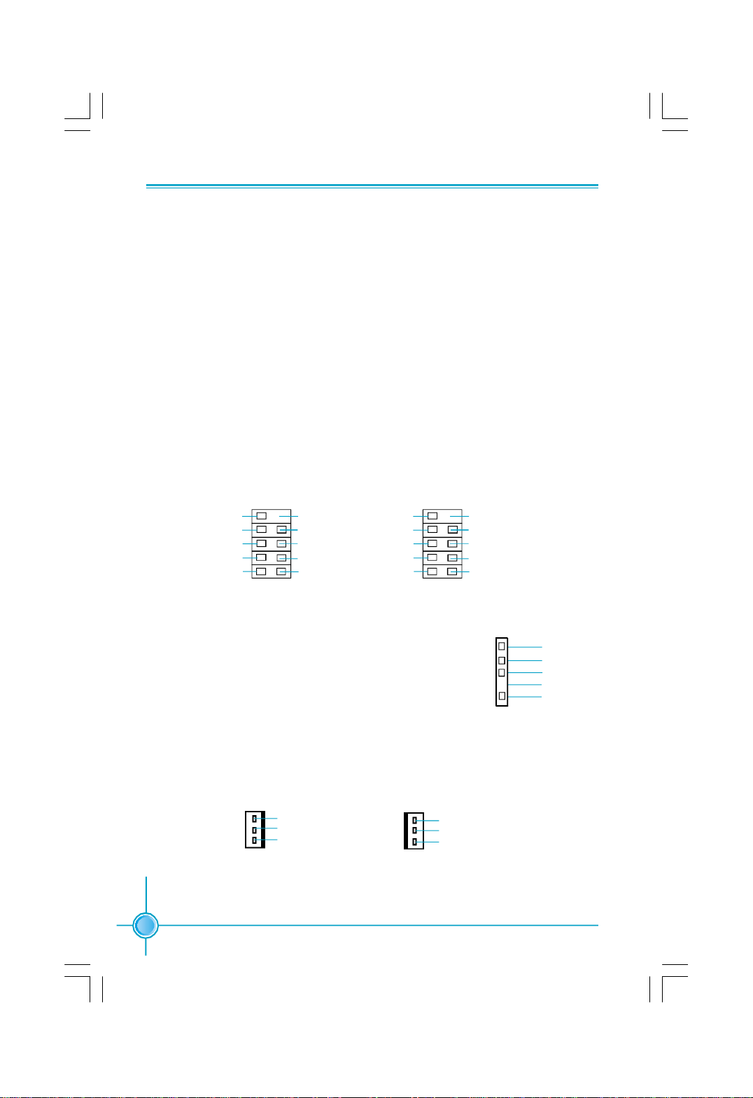
Clear CMOS Jumper: CLR_CMOS
This motherboard uses the CMOS RAM to store all
the set parameters. The CMOS can be cleared by
removing the CMOS jumper. Reference the following
process.
1. Turn off the AC power supply and short pins 1 and 2
on the jumper.
2. Return the jumper to the normal setting (locking pins
2 and 3 together with the jumper cap).
3. Turn on the system. The BIOS is returned to the
default settings.
Jumper Diagram Definition Description
1-2 Set pin 1 and pin 2 closed
2-3 Set pin 2 and pin 3 closed
Closed Set the pin closed
Open Set the pin opened
1
1
1
1
1
1
Clear CMOS Jumper
Normal
(default)
Clear
3
2
1
3
2
1
Warning:
1.Disconnect the power cable before adjusting the jumper
settings.
2.DO NOT clear the CMOS while the system is turned on.
 Loading...