


A74ML 3.0 Series Motherboard
User’s Manual

Statement:
This manual is the intellectual property of Foxconn, Inc. Although the information in this manual may be changed or modified at any time, Foxconn does not obligate itself to inform the user of these changes.
Trademark:
All trademarks are the property of their respective owners.
Version:
User’s Manual V1.0 for A74ML 3.0 Series motherboard.
P/N: 3A2225200-000-G
Symbol description:
C |
|
|
T |
I O |
N |
! |
|
|
U |
|
|
||||
|
A |
|
|
|
Caution : refers to important information that can help you to use motherboard |
||
|
|
|
|
|
|||
|
|
|
|
|
|
better, and tells you how to avoid problems.
|
|
NI |
|
|
|
R |
N |
||
A |
|
|
G! |
|
W |
|
|
|
|
Warning : indicating a potential risk of hardware damage or physical injury may exist.
 WEEE:
WEEE:
The use of this symbol indicates that this product may not be treated as household waste. By ensuring this product is disposed of correctly, you will help prevent potential negative consequences for the environment and human health, which could otherwise be caused by inappropriate waste handling of this product. For more detailed information about recycling of this product, please contact your local city office, your household waste disposal service or the shop where you purchased this product.
More information:
If you want more information about our products, please visit Foxconn’s website: http://www.foxconnchannel.com
© All rights reserved.
All trade names are registered trademarks of respective manufacturers listed.
All images are for reference only, please refer to the physical motherboard for specific features.

Declaration of conformity
HON HAI PRECISION INDUSTRY COMPANY LTD
66 , CHUNG SHAN RD., TU-CHENG INDUSTRIAL DISTRICT,
TAIPEI HSIEN, TAIWAN, R.O.C.
declares that the product
Motherboard A74ML 3.0/A74ML-K 3.0
is in conformity with
(reference to the specification under which conformity is declared in accordance with 89/336 EEC-EMC Directive)
■ EN 55022:1998/A2: 2003 Limits and methods of measurements of radio disturbance characteristics of information technology equipment
■ EN 61000-3-2/:2000 Electromagnetic compatibility (EMC)
Part 3: Limits
Section 2: Limits for harmonic current emissions (equipment input current <= 16A per phase)
■ EN 61000-3-3/A1:2001 Electromagnetic compatibility (EMC)
Part 3: Limits
Section 2: Limits of voltage fluctuations and flicker in low voltage supply systems for equipment with rated current <= 16A
■ EN 55024/A2:2003 Information technology equipment-Immunity characteristics limits and methods of measurement
Signature : |
Place / Date : TAIPEI/2009 |
Printed Name : James Liang

Declaration of conformity
Trade Name: |
FOXCONN |
Model Name: |
A74ML 3.0/A74ML-K 3.0 |
Responsible Party: |
PCE Industry Inc. |
Address: |
458 E. Lambert Rd. |
|
Fullerton, CA 92835 |
Telephone: |
714-738-8868 |
Facsimile: |
714-738-8838 |
Equipment Classification: |
FCC Class B Subassembly |
Type of Product: |
Motherboard |
Manufacturer: |
HON HAI PRECISION INDUSTRY |
|
COMPANY LTD |
Address: |
66 , CHUNG SHAN RD., TU-CHENG |
|
INDUSTRIAL DISTRICT, TAIPEI HSIEN, |
|
TAIWAN, R.O.C. |
Supplementary Information: |
|
This device complies with Part 15 of the FCC Rules. Operation is subject to the following two conditions : (1) this device may not cause harmful interference, and (2) this device must accept any interference received, including interference that may cause undesired operation.
Tested to comply with FCC standards.
Signature : |
Date : 2009 |
Installation Precautions
|
|
NI |
|
|
|
R |
N |
||
A |
|
|
G! |
|
W |
|
|
|
|
|
|
|
|
|
|
■ |
Electrostatic discharge (ESD) is the sudden and momentary electric current |
|
|
|
|
|
|
|
that flows between two objects at different electrical potentials. Normally it |
|
|
|
|
|
|
|
comes out as a spark which will quickly damage your electronic equipment. |
|
|
|
|
|
|
|
Please wear an electrostatic discharge (ESD) wrist strap when handling |
|
|
|
|
|
|
|
components such as a motherboard, CPU or memory. |
|
|
|
|
|
|
■ |
Ensure that the DC power supply is turned off before installing or removing |
|
|
|
|
|
|
|
CPU, memory, expansion cards or other peripherals. It is recommended to |
|
|
|
|
|
|
|
unplug the AC power cord from the power supply outlet. Failure to unplug |
|
|
|
|
|
|
|
the power supply cord may result in serious damage to your system. |
|
|
|
T |
I O |
N |
! |
|
|
|
U |
|
|
|||
|
A |
|
|
|
|||
C |
|
|
|
|
|||
|
|
|
|
Please carefully read the following procedures to install your computer : |
|||
|
|
|
|
|
|||
|
|
|
|
|
|
■ |
It is suggested to select high-quality, certified fans in order to avoid damage |
|
|
|
|
|
|
|
to the motherboard and CPU due to high temperature. Never turn on the |
|
|
|
|
|
|
|
computer if the CPU fan is not properly installed. |
|
|
|
|
|
|
■ |
We cannot guarantee that your system can operate normally when your |
|
|
|
|
|
|
|
CPU is overclocked. Normal operation depends on the overclocking capac- |
|
|
|
|
|
|
|
ity of your device. |
|
|
|
|
|
|
■ |
If there is any, when connecting USB, audio, RS232 COM, IrDA or S/PDIF |
|
|
|
|
|
|
|
cables to the internal connectors on the motherboard, make sure their |
|
|
|
|
|
|
|
pinouts are matching with the connectors on the motherboard. Incorrect con- |
|
|
|
|
|
|
|
nections might damage the motherboard. |
|
|
|
|
|
|
■ |
When handling the motherboard, avoid touching any metal leads or connec- |
|
|
|
|
|
|
|
tors. |
|
|
|
|
|
|
■ |
If there is a PCI Express x16 graphics card installed in your system, we |
|
|
|
|
|
|
|
recommend using a 24-pin ATX power supply to get the best performance. |
|
|
|
|
|
|
■ |
Before turning on the power, please make sure the power supply AC input |
|
|
|
|
|
|
|
voltage setting has been configured to the local standard. |
|
|
|
|
|
|
■ |
To prevent damage to the motherboard, do not allow screws to come in contact |
|
|
|
|
|
|
|
with the motherboard circuit or its components. Also, make sure there are no |
|
|
|
|
|
|
|
leftover screws or metal components placed on the motherboard or within the |
|
|
|
|
|
|
|
computer casing. |
|
|
|
|
|
|
■ |
If you are uncertain about any installation steps or have a problem related to |
the use of the product, please consult a certified computer technician.

Table of Contents |
|
Chapter 1 Product Introduction |
|
Product Specifications.............................................................................. |
2 |
Layout....................................................................................................... |
4 |
Back Panel Connectors............................................................................ |
5 |
Chapter 2 Hardware Install |
|
Install the CPU and CPU Cooler............................................................... |
8 |
Install the Memory................................................................................... |
10 |
Install an Expansion Card....................................................................... |
12 |
Install other Internal Connectors............................................................. |
13 |
Jumpers.................................................................................................. |
17 |
Chapter 3 BIOS Setup |
|
Enter BIOS Setup................................................................................... |
19 |
Main Menu.............................................................................................. |
19 |
System Information................................................................................. |
21 |
Advanced BIOS Features....................................................................... |
23 |
Fox Central Control Unit......................................................................... |
25 |
Advanced Chipset Features.................................................................... |
29 |
Integrated Peripherals............................................................................. |
33 |
Power Management Setup..................................................................... |
38 |
PC Health Status.................................................................................... |
40 |
BIOS Security Features.......................................................................... |
41 |
Load Optimal Defaults............................................................................ |
42 |
Save & Exit Setup................................................................................... |
42 |
Exit Without Saving................................................................................. |
42 |
Chapter 4 CD Instruction |
|
Utility CD content.................................................................................... |
44 |
Install driver and utility............................................................................ |
45 |
FOX ONE |
|
Main Page......................................................................................... |
47 |
CPU Control...................................................................................... |
51 |
Frequency Control............................................................................ |
53 |
Limit Setting...................................................................................... |
54 |
Voltage Control................................................................................. |
56 |
Fan Control....................................................................................... |
57 |
FOX LiveUpdate |
|
Local Update..................................................................................... |
58 |
Online Update................................................................................... |
60 |

Configure ......................................................................................... |
63 |
About & Help..................................................................................... |
65 |
FOX LOGO............................................................................................. |
66 |
FOX DMI................................................................................................. |
67 |
Chapter 5 RAID Configuration |
|
RAID Configuration Introduction............................................................. |
70 |
FastBuild Driver...................................................................................... |
72 |
Create a RAID Driver Diskette................................................................ |
74 |
RAID Enable in BIOS.............................................................................. |
76 |
Select a RAID Array for Use................................................................... |
76 |
Install a New Windows XP...................................................................... |
89 |
Setting Up a Non-Bootable RAID Array.................................................. |
93 |
Technical Support :
Support
Website :
http://www.foxconnchannel.com
Support Website :
http://www.foxconnsupport.com
Worldwide Online Contact Support :
http://www.foxconnsupport.com/inquiry.aspx
CPU Support List : http://www.foxconnsupport.com/cpusupportlist.aspx
Memory, VGA Compatibility List :
http://www.foxconnsupport.com/complist.aspx

Thank you for buying Foxconn A74ML 3.0 Series motherboard. Foxconn products are engineered to maximize computing power, providing only what you need for break-through performance.
With advanced overclocking capability and a range of connectivity features for today multi-media computing requirements, A74ML 3.0/A74ML-K 3.0 enables you to unleash more power from your computer.
This chapter includes the following information:
■Product Specifications
■Layout
■Back Panel Connectors

1
1-1 Product Specifications
CPU |
Support AMD PhenomTM II, AthlonTM, SempronTM, AM3 socket processors |
|
HyperTransport |
2000MT/s |
|
Chipset |
North Bridge: AMD RS740G |
|
|
South Bridge: AMD SB710 |
|
Memory |
2 x 240-pin DDR3 DIMM sockets |
|
|
Support up to 8GB of system memory |
|
|
Dual channel DDR3 1333/1066/800MHz architecture |
|
Audio |
VIA 6-channel audio chip |
|
|
High Definition Audio |
|
|
2/4/5.1-channel |
|
|
Support for S/PDIF Out |
|
|
Support Jack-Sensing function |
|
LAN |
Realtek 10/100Mb/s LAN chip |
(A74ML 3.0) |
|
Realtek 10/100/1000Mb/s LAN chip |
(A74ML-K 3.0) |
Expansion Slots |
1 x PCI Express x16 slot |
|
|
1 x PCI Express x1 slot |
|
|
2 x PCI slots |
|
Onboard Serial ATA |
4 x SATA connectors |
|
|
300MB/s data transfer rate |
|
|
Support hot plug and NCQ (Native Command Queuing ) |
|
USB |
Support hot plug |
|
|
Support up to 10 x USB 2.0 ports (4 rear panel ports, 3 onboard USB |
|
|
headers supporting 6 extra ports) |
|
|
Support USB 2.0 protocol up to 480Mb/s |
|
Internal Connectors |
1 x 24-pin ATX main power connector |
|
|
1 x 4-pin ATX 12V power connector |
|
|
1 x IDE connector |
|
|
4 x SATA connectors |
|
|
3 x USB 2.0 connectors (supporting 6 x USB devices) |
|
|
1 x CPU fan header (4-pin) |
|
|
1 x System fan header (4-pin) |
|
|
1 x Front Audio connector |
|
|
1 x CD_IN connector |
|
|
1 x S/PDIF_OUT connector |
|
|
1 x Speaker connector |
|
|
1 x Front panel connector |
|
|
1 x Chassis intrusion alarm header (INTR) |
|
Back Panel |
1 x PS/2 keyboard port |
|
Connectors |
1 x PS/2 mouse port |
|
|
1 x VGA port |
|
|
1 x DVI-D port |
|
|
4 x USB 2.0 ports |
|
|
1 x RJ-45 LAN port |
|

|
|
6-channel Audio ports |
|
Hardware Monitor |
System voltage detection |
|
|
CPU/System temperature detection |
|
|
CPU/System fan speed detection |
|
|
CPU/System fan speed control |
PCI Express x1 |
Support 250MB/s (500MB/s concurrent) bandwidth |
|
|
|
Low power consumption and power management features |
PCI Express x16 |
Support 4GB/s (8GB/s concurrent) bandwidth |
|
|
|
Low power consumption and power management features |
Green Function |
Support ACPI (Advanced Configuration and Power Interface) |
|
|
|
Support S0 (normal), S1 (power on suspend), S3 (suspend to RAM), S4 |
|
|
(suspend to disk), and S5 (soft - off) |
Bundled Software |
FOX ONE |
|
|
|
FOX LiveUpdate |
|
|
FOX LOGO |
|
|
FOX DMI |
Operating System |
Support for Microsoft® Windows® Vista/XP |
|
Form Factor |
Micro ATX Form Factor, 9.6 inches x 8.4 inches (24.4cm x 21.4cm) |
|
1
|
|
|
T |
I |
O |
N |
|
|
U |
|
|||
|
A |
|
|
|
||
C |
|
|
|
|
||
|
|
|
|
|
||
|
|
|
|
|
|
!
The chipset driver of this motherboard does not support Windows® 2000.

1
1-2 Layout
6 |
5 |
4 |
3 |
2 |
1 |
7
8
9
10
11
12
13
14 |
15 |
16 |
17 |
18 |
22
21
20
19
1. |
4-pin ATX 12V Power Connector |
13. |
Front Panel Connector |
2. |
SYS_FAN Header |
14. |
SATA Connectors |
3. |
North Bridge: AMD RS740G |
15. |
South Bridge: AMD SB710 |
4. |
PCI Express x1 Slot |
16. |
24-pin ATX Power Connector |
5. |
PCI Express x16 Slot |
17. |
IDE Connector |
6. |
PCI Slots |
18. |
Chassis Intrusion Alarm Header |
7. |
Front Audio Connector |
19. |
COM1 Header |
8. |
CD_IN Connector |
20. |
DDR3 DIMM Slots |
9. |
S/PDIF Out Connector |
21. |
CPU_FAN Header |
10. Speaker Connector |
22. |
CPU Socket |
|
11.Front USB Connectors
12.Clear CMOS Jumper
Note : The above motherboard layout is for reference only, please refer to the physical motherboard for detail.
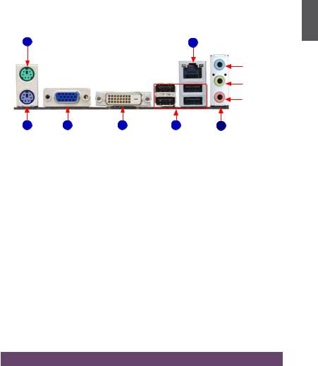
1-3 Back Panel Connectors
|
|
|
|
1 |
PS/2 Mouse Port |
|
|
LAN Port |
|
1 |
|
|
7 |
|
|
|
|
|
Line In |
|
|
|
|
Line Out |
|
|
|
|
Microphone |
2 |
3 |
4 |
5 |
6 |
PS/2 Keyboard Port |
VGA Port |
DVI-D Port |
USB Ports |
Audio Ports |
1.PS/2 Mouse Port
Use the upper port (green) to connect a PS/2 mouse.
2.PS/2 Keyboard Port
Use the lower port (purple) to connect a PS/2 keyboard.
3.VGA Port
To connect with external display devices, such as monitor or LCD display.
4.DVI-D Port
The DVI-D port supports DVI-D specification. Connect a monitor that suppors DVI-D connection to this port.
5.USB Ports
The USB ports support the USB 2.0/1.1 specification. Use these ports for USB devices such as an USB keyboard/mouse, USB printer, USB flash drive and etc.
6.Audio Ports
For the definition of each audio port, please refer to the table below :
Port |
2-channel |
4-channel |
5.1-channel |
Blue |
Line In |
Rear Speaker Out* |
Rear Speaker Out* |
Green |
Line Out |
Front Speaker Out |
Front Speaker Out |
Pink |
Microphone In |
Microphone In |
Center/Subwoofer Out* |
* : Please refer to Chapter 4, and install the Realtek audio driver (in CD) to assign the audio output ports for different applications of 2/4/5.1 channels. The fundamental audio outputs are depicted in the table above.

1
7.RJ-45 LAN Port
The Ethernet LAN port provides Internet connection at up to 10/100/1000Mb/s data rate.
|
|
|
|
|
|
LAN Type |
Left: Active |
|
Right: Link |
|
|
|||
|
|
|
|
|
|
Status |
Description |
Status |
Description |
|
|
|||
|
|
|
|
|
|
|
|
|
|
|||||
|
|
|
|
|
|
|
|
Off |
No Link |
Off |
No Link |
|
|
|
|
|
|
|
|
|
|
100M |
Green |
Data Activity |
Orange |
10/100Mb/s Connection |
|||
|
|
|
|
|
|
|
|
Blinking |
||||||
|
|
|
|
|
|
|
|
|
|
|
|
|
|
|
|
|
|
|
|
|
|
|
Off |
No Link |
Off |
No Link |
|
|
|
|
|
|
|
|
|
|
|
|
|
|
|
|
|
|
|
|
|
|
|
|
|
1000M |
Green |
|
Off |
10Mb/s Connection |
|
|
|
|
|
|
|
|
|
|
Data Activity |
Green |
100Mb/s Connection |
|||||
|
|
|
|
|
|
|
|
Blinking |
||||||
|
|
|
|
|
|
|
|
|
Orange |
1000Mb/s Connection |
||||
|
|
|
|
|
|
|
|
|
|
|||||
|
|
|
|
|
|
|
|
|
|
|
Active |
Link |
||
|
|
|
|
|
N |
|
|
|
|
|
LED |
LED |
||
|
A |
U |
T |
I O |
! |
|
|
|
|
|
|
|
|
|
|
|
|
|
|
|
|
|
|
|
|||||
|
|
|
|
|
|
|
|
|
|
|
||||
C |
|
|
|
|
|
|
|
|
|
|
|
|||
|
|
|
|
A74ML 3.0 supports 10/100Mb/s Ethernet. |
|
|
|
|
||||||
|
|
|
|
|
|
|
|
|
||||||
A74ML-K 3.0 supports 10/100/1000Mb/s Ethernet.

This chapter introduces the hardware installation process, including the installation of the CPU, memory, power supply, slots, pin headers and the mounting of jumpers. Caution should be exercised during the installation of these modules. Please refer to the motherboard layout prior to any installation and read the contents in this chapter carefully.
This chapter includes the following information :
■Install the CPU and CPU Cooler
■Install the Memory
■Install an Expansion Card
■Install other Internal Connectors
■Jumpers
Please visit the following website for more supporting information about your motherboard.
CPU Support List: http://www.foxconnsupport.com/cpusupportlist.aspx
Memory, VGA Compatibility List: http://www.foxconnsupport.com/complist.aspx

2-1 Install the CPU and CPU Cooler
|
|
|
T |
I |
O |
N |
|
|
U |
|
|||
|
A |
|
|
|
||
C |
|
|
|
|
||
|
|
|
|
|
||
|
|
|
|
|
|
!Read the following guidelines before you begin to install the CPU:
|
■ |
Make sure that the motherboard supports the CPU. |
|
||
2 |
■ |
Always turn off the computer and unplug the power cord from the power supply before |
|
installing the CPU to prevent hardware damage. |
|
|
|
|
|
■ |
Locate the Pin-1 of the CPU. The CPU cannot be inserted if oriented incorrectly. |
|
■ |
Apply an even and thin layer of thermal grease on the surface of the CPU. |
|
■ |
Do not turn on the computer if the CPU cooler is not installed, otherwise overheating |
|
|
and damage of the CPU may occur. |
|
■ |
Set the CPU host frequency in accordance with the CPU specifications. It is not |
|
|
recommended that the system bus frequency be set beyond hardware specifications |
|
|
since it does not meet the standard requirements for the peripherals. If you want to |
|
|
set the frequency beyond the standard specifications, please do so according to your |
|
|
hardware specifications including the CPU, graphics card, memory, hard drive, etc. |
Install the CPU
Locate the Pin-1 CPU triangle mark and the Pin-1 of the CPU socket.
Pin-1 corner of the |
Pin-1 triangle |
|
marking of CPU |
||
CPU socket |
||
|
1. Release the CPU socket lever.
2.Align Pin-1 of the CPU with the CPU socket, and gently put the CPU onto the socket.

3.When CPU is properly seated, push the CPU socket lever back to its locked position.
2
Install the CPU Cooler
Follow the steps below to correctly install the CPU cooler. (The following procedures use Foxconn cooler as the example.)
|
|
|
T |
I |
O |
N |
|
|
U |
|
|||
|
A |
|
|
|
||
C |
|
|
|
|
||
|
|
|
|
|
||
|
|
|
|
|
|
1.Apply and spread an even thermal grease on the surface of CPU.
3.Buckle the heatsink at another side, and press the fasten lever down to tightly seat the cooler.
2.Buckle the heatsink firmly at one side of the stand.
4.Attach the 3-wire CPU cooler connector to the CPU fan header on the motherboard .
!
Use extreme care when removing the CPU cooler because the thermal grease may adhere to the CPU. Inadequately removing the CPU cooler may damage the CPU.

2-2 Install the Memory
|
|
|
T |
I |
O |
N |
|
|
U |
|
|||
|
A |
|
|
|
||
C |
|
|
|
|
||
|
|
|
|
|
||
|
|
|
|
|
|
!Read the following guidelines before you begin to install the memory :
|
■ |
Make sure that the motherboard supports the memory. It is recommended that memory |
|
|
|||
2 |
|
of the same capacity, brand, speed, and chips be used. |
|
■ |
Always turn off the computer and unplug the power cord from the power outlet before |
||
|
|||
|
|
installing the memory to prevent hardware damage. |
|
|
■ |
Memory modules have a foolproof design. A memory module can be installed in only |
|
|
|
one direction. If you are unable to insert the memory, switch the direction. |
Dual Channel Memory Configuration
This motherboard provides two DDR3 memory sockets and supports Dual Channel Technology. When memory is installed, the BIOS will automatically check the memory in your system.
Two DDR3 memory sockets are divided into two channels :
Channel 0 : DIMM1
Channel 1 : DIMM2
The combinations of DIMM modules are :
|
|
|
|
|
|
|
|
|
DIMM1 |
DIMM2 |
|
|
|
|
|
|
|
|
|
Single Channel |
DS/SS |
- |
|
|
|
|
|
|
|
|
|
|
|
|
|
|
|
|
|
|
|
|
|
Single Channel |
- |
DS/SS |
|
|
|
|
|
|
|
|
|
Dual Channel |
DS/SS |
DS/SS |
|
|
|
|
|
|
N |
|
|
(DS : Double |
Side, SS : Single Side, |
- : No Memory) |
|
|
|
|
T |
I O |
! |
|
|
|
|
|
|
|
|
U |
|
|
|
|
|
|
|||
|
A |
|
|
|
|
|
|
|
|||
C |
|
|
|
|
|
|
|
|
|||
|
|
|
|
|
|
|
|
|
|||
|
|
|
|
|
It is recommended that memory of the same capacity, brand, speed, and chips be |
||||||
|
|
|
|
|
|
||||||
used and please select dual channel first to achieve optimum performance.
10

Installing a Memory
|
|
|
T |
I O |
N |
! |
|
|
|
U |
|
|
|||
|
A |
|
|
|
|||
C |
|
|
|
|
|||
|
|
|
|
|
|||
|
|
|
|
|
Before installing a memory module, make sure to turn off the computer and unplug the |
||
|
|
|
|
|
|
|
power cord from the power outlet to prevent damage to the memory module. Be sure |
|
|
|
|
|
|
|
to install DDR3 DIMMs on this motherboard. |
2
 96-Pin 144-Pin
 Notch
Notch
If you take a look at front side of memory module, it has asymmetric pin counts on both sides separated by a notch in the middle, so it can only fit in one direction. Follow the steps below to correctly install your memory modules into the sockets.
Step 1:
Spread the clips at both ends of the memory socket. Place the memory module onto the socket, then put your fingers on top edge of the module, and push  it down firmly and seat it vertically into the memory
socket.
Step 2:
The clips at both ends of the socket will snap into place when the memory module is securely inserted.
11
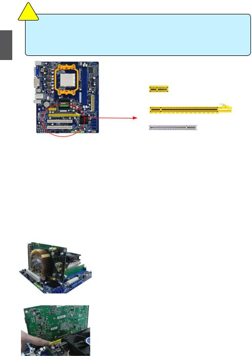
2-3 Install an Expansion Card
|
|
|
T |
I |
O |
N |
|
|
U |
|
|||
|
A |
|
|
|
||
C |
|
|
|
|
||
|
|
|
|
|
||
|
|
|
|
|
|
2
!
■Make sure the motherboard supports the expansion card. Carefully read the manual that came with your expansion card.
■Always turn off the computer and unplug the power cord from the power outlet before installing an expansion card to prevent hardware damage.
PCI Express x1
PCI Express x16
PCI
Follow the steps below to correctly install your expansion card in the expansion slot.
1.Locate an expansion slot that supports your card. Remove the metal slot cover from the chassis back panel.
2.Align the card with the slot, and press down on the card until it is fully seated in the slot.
3.Make sure the metal contacts on the card are completely inserted into the slot.
4.Secure the card's metal bracket to the chassis back panel with a screw.
5.After installing all expansion cards, replace the chassis cover.
6.Turn on your computer. If necessary, go to BIOS Setup to make any required BIOS changes for your expansion card(s).
7.Install the driver provided with the expansion card in your operating system.
Installing and Removing a PCI Express x16 Graphics Card :
• Installing a Graphics Card:
Gently insert the graphics card into the PCI Express x16 slot. Make sure the graphics card is locked by the latch at the end of the PCI Express x16 slot.
• Removing the Card:
Push the latch at the end of the PCI Express x16 slot to release the card and then pull the card straight up from the slot.
12

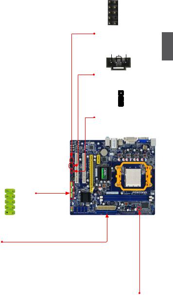
2-4 Install other Internal Connectors
Power Connectors
This motherboard uses an ATX power supply. In order not to damage any device, make sure all the devices have been installed properly before applying the power supply.
24-pin ATX power connector : PWR1
PWR1 is the ATX power supply connector. Make sure that the power supply cable and pins are properly aligned with the connector on the motherboard. Firmly plug the power supply cable into the connector and make sure it is secure.
|
|
|
|
|
|
|
|
|
|
Pin # |
Definition |
Pin # |
Definition |
|
|
|
|
|
|
|
|
|
|
|
|
|
|
|
|
|
|
|
|
|
|
|
|
|
|
1 |
3.3V |
13 |
3.3V |
|
|
|
|
|
|
|
|
|
|
|
|
|
|
|
|
|
|
|
|
|
|
|
|
|
|
2 |
3.3V |
14 |
-12V |
|
|
|
|
|
|
|
|
|
|
|
|
|
|
|
|
|
|
|
|
|
|
|
|
|
|
3 |
GND |
15 |
GND |
|
|
|
|
|
|
|
|
|
|
|
|
|
|
|
|
|
|
|
|
|
|
|
|
|
|
4 |
+5V |
16 |
PS_ON(Soft On/Off) |
|
|
|
|
|
|
|
|
|
|
|
|
|
|
|
|
|
|
|
|
|
|
|
|
|
|
5 |
GND |
17 |
GND |
|
|
|
|
|
|
|
|
|
|
|
|
|
|
|
|
|
|
|
|
|
|
|
|
|
|
6 |
+5V |
18 |
GND |
|
|
|
|
|
|
|
|
|
|
|
|
|
|
|
|
|
|
|
|
|
|
|
|
|
|
7 |
GND |
19 |
GND |
|
|
|
|
|
|
|
|
|
|
|
|
|
|
|
|
|
|
|
|
|
|
|
|
|
|
8 |
Power Good |
20 |
NC |
|
|
|
|
|
|
|
|
|
|
|
|
|
|
|
|
|
|
|
|
|
|
|
|
|
|
9 |
+5V SB(Stand by +5V) |
21 |
+5V |
|
|
|
|
|
|
|
|
|
|
|
|
|
|
|
|
|
|
|
|
24 |
|
|
|
13 |
10 |
+12V |
22 |
+5V |
|
|
|
|
|
|
|
|
|
|
|
|
11 |
+12V |
23 |
+5V |
|
|
|
|
|
|
|
|
|
|
|
|
|
|
|
|
|
|
|
|
|
|
|
|
|
|
12 |
3.3V |
24 |
GND |
|
|
|
|
|
12 |
|
PWR1 |
1 |
|
|
|
|
|
||
|
|
|
|
|
|
|
|
|
|
|||||
|
|
|
|
|
|
|
|
|
|
|
|
|
||
|
|
|
|
|
|
|
|
|
|
|
|
|
Pin No. 24 |
|
|
|
|
T |
I O |
N |
! |
|
|
|
|
|
|
|
|
|
|
U |
|
|
|
|
|
|
|
|
|
|||
|
A |
|
|
|
|
|
|
|
|
|
|
|||
C |
|
|
|
|
|
|
|
|
|
|
|
|||
|
|
|
|
|
|
|
|
|
|
|
|
|||
|
|
|
|
|
We recommend you using a 24-pin power supply. |
|
|
|
||||||
If you are using a 20-pin power supply, you need to align the ATX power connector according to the picture.
20-Pin Power
4-pin ATX 12 V Power Connector : PWR2
Connect the 4-pin ATX 12V power supply to PWR2 and provides power to the CPU.
3 |
1 |
|
|
|
|
|
|
|
|
Pin # |
Definition |
|
|
|
|
|
|
|
|
|
|
1 |
GND |
+12V |
|
|
GND |
2 |
GND |
|
|
|
|
||
|
|
|
|
3 |
+12V |
|
|
|
|
|
|
4 |
2 |
|
4 |
+12V |
|
PWR2
2
13
2
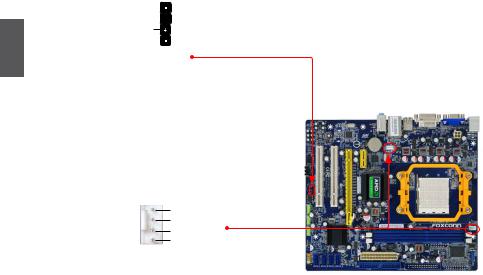
Front Panel Connector : FP1
This motherboard includes one connector for connecting the front panel switch and LED Indicators.
Hard Disk LED Connector (HDD-LED)
Connect to the chassis front panel IDE indicator LED. It indicates the active status of the hard disks. This 2-pin connector is directional with +/- sign.
Reset Switch (RESET-SW)
Attach the connector to the Reset switch on the front panel of the case; the system will restart when the switch is pressed.
Power LED Connector (PWR-LED)
Connect to the power LED indicator on the front panel of the chassis. The Power LED indicates the system’s status. When the system is in operation (S0 status), the LED is on. When the system gets into sleep mode (S1) , the LED is blinking; When the system is in S3/S4 sleep state or power off mode (S5), the LED is off. This 2-pin connector is directional with +/- sign.
Power Switch Connector (PWR-SW)
Connect to the power button on the front panel of the chassis. Push this switch allows the system to be turned on and off rather than using the power supply button.
Serial ATA Connectors : SATA_1/2/3/4
The Serial ATA connector is used to connect with SATA Hard Disk or CD devices which support this feature. The current Serial ATA II interface allows up to 300MB/s data transfer rate.
+ |
1 |
|
2 |
+ |
|||||
HDD-LED |
|
|
|
|
|
PWR-LED |
|||
- |
|
|
|
|
|
|
- |
||
RESET-SW |
|
|
|
|
|
|
PWR-SW |
||
|
|
|
|
|
|
||||
NC |
|
|
|
|
|
|
|
|
EMPTY |
|
|
|
|
10 |
|
||||
9 |
|
|
|||||||
FP1
1
GND
TX+  TX-
TX-
GND
 RX-
RX-
 RX+
RX+
 GND
GND
 SATA_1/2/3/4
COM Connector: COM1 |
|
1 |
2 |
|
|
|
|
|
This motherboard supports one serial RS232 COM port for |
RLSD |
|
|
|
|
|
|
SIN |
|
|
|
|
|||||
legacy compatibility. User must purchase another RS232 |
SOUT |
|
|
|
|
|
|
DTR |
|
|
|
|
|
|
|||
cable with a 9-pin D-sub connector at one end to connect |
GND |
|
|
|
|
|
|
DSR |
|
|
|
|
|
|
|||
with the external RS232 dvice and another end with 10-pin |
RTS |
|
|
|
|
|
|
CTS |
|
|
|
|
|
|
|||
femal connector to connect with COM1 connector in the |
RI |
|
|
|
|
|
|
EMPTY |
9 |
10 |
|
|
|
||||
motherboard. |
|
|
|
|
|
|||
|
|
COM1 |
||||||
14
Audio Connector : F_AUDIO
The audio connector supports HD Audio standard. It provides the Front Audio output choice.
Audio Connector : CD_IN
CD_IN is a Sony standard audio connector, it can be connected to a CD/DVD-ROM drive through a CD/DVD audio cable.
S/PDIF Connector : SPDIF_OUT
The connector is used for S/PDIF output.
USB Connectors : F_USB 1/2/3
In addition to the four USB ports on the rear panel, this product also provides three 10-pin USB headers on its motherboard. By connecting through USB cables with them, user can quickly expand another six USB ports
on the front panel. |
1 |
2 |
|
|
||||
|
|
|
||||||
|
VCC |
|
|
|
|
|
|
VCC |
|
|
|
|
|
|
|
||
|
D- |
|
|
|
|
|
|
D- |
|
|
|
|
|
|
|
||
|
D+ |
|
|
|
|
|
|
D+ |
|
|
|
|
|
|
|
||
|
GND |
|
|
|
|
|
|
GND |
|
|
|
|
|
|
|
||
|
EMPTY |
|
|
10 |
|
NC |
||
|
|
|
|
|||||
|
9 |
|
|
|||||
F_USB 1/2/3
IDE Connector : PIDE
With the provided Ultra DMA IDE ribbon cable, you can connect to any IDE type of hard disk and CD/DVD ROM/RW drive.
Chassis Intruder Alarm Connector : INTR
The connector can be connected to a security switch on the chassis. The system can detect the chassis intrusion through the function of this connector. If eventually the chassis is closed, the system will send a message out.
1 |
2 |
|
||||||
PORT1_L |
|
|
|
|
|
AUD_GND |
||
|
|
|
|
|
||||
PORT1_R |
|
|
|
|
|
|
PRESENCE_J |
|
|
|
|
|
|
|
|
||
PORT2_R |
|
|
|
|
|
SENSE1_RETURN |
||
|
|
|
|
|
|
|||
SENSE_SEND |
|
|
|
|
|
EMPTY |
||
|
|
|
|
|||||
PORT2_L |
|
|
|
|
|
SENSE2_RETURN |
||
|
|
|
|
|||||
9 10
F_AUDIO
2
CD_L GND CD_R
1
CD_IN
+5V  1 EMPTY
 2 SPDIF_OUT
  3 GND
3 GND  4
4
SPDIF_OUT
1 INTRUDERJ 

 GND
GND
INTR
15
2
Speaker Connector : SPEAKER
The speaker connector is used to connect speaker of the chassis.
SPKJ  1
1
EMPTY  2
2
NC 3
SPKJ  4
4
SPEAKER
Fan Connectors : CPU_FAN, SYS_FAN
There are two main fan headers on this motherboard. The fan speed can be controlled and monitored in “PC Health Status” section of the BIOS Setup. These fans can be automatically turned off after the system enters S3, S4 and S5 sleeping states.
1GND POWER SENSE CONTROL
CPU_FAN/SYS_FAN
16

2-5 Jumpers
For some features needed, users can change the jumper settings on this motherboard to modify them. This section explains how to use the various functions of this motherboard by changing the jumper settings. Users should read the following content carefully prior to modifying any jumper setting.
Description of Jumpers
1.For any jumper on this motherboard, pin 1 can be identified by the bold silkscreen next to it.
However, in this manual, pin 1 is simply labeled as “1”.
2.The following table explains different types of the jumper settings. "Closed" means placing a jumper cap on the two pins to temporarily short them. The shorting can also be done by touching two pins by a screwdriver for a few seconds, but using jumper cap is recommended. It can prevent hazardous ESD (Electrical Static Discharge) problem.
Jumper |
Diagram |
Definition |
Description |
|
1 |
1-2 |
Set Pin 1 and Pin 2 closed |
1 |
|
2-3 |
Set Pin 2 and Pin 3 closed |
|
1 |
Clear CMOS Jumper: CLR_CMOS
The motherboard uses CMOS RAM to store the basic hardware information (such as BIOS data, date, time information, hardware password...etc.). Clear CMOS data is the fast way to go back to factory default when the BIOS settings were mistakenly modified.
The steps to clear CMOS data are :
1.Turn off the computer, unplug the power cord from the power outlet.
2.Remove jumper cap from pins 2-3, put it onto pins 1-2 to short them. This will clear CMOS data.
3.Return the setting to its original with pins 2-3 closed.
4.Plug in the power cord to your computer and turn it on.
5.GotoBIOSSetuptoconfigurenewsystemasdescribed in next chapter.
1
Clear  2
2  3
3
Normal |
1 |
|
2 |
||
(Default) |
||
3 |
||
|
||
CLR_CMOS |
|
|
|
NI |
|
|
|
R |
N |
||
A |
|
|
G! |
|
W |
|
|
|
|
■Disconnect the power cable before adjusting the jumper settings.
■Do not clear the CMOS while the system is turned on.
2
17
This chapter tells how to change system settings through the BIOS Setup menus. Detailed descriptions of the BIOS parameters are also provided.
You have to run the Setup Program when the following cases occur:
1.An error message appears on the screen during the system Power On Self Test (POST) process.
2.You want to change the default CMOS settings.
This chapter includes the following information :
■Enter BIOS Setup
■Main Menu
■System Information
■Advanced BIOS Features
■Fox Central Control Unit
■Advanced Chipset Features
■Integrated Peripherals
■Power Management Setup
■PC Health Status
■BIOS Security Features
■Load Optimal Defaults
■Save & Exit Setup
■Exit Without Saving
Since BIOS could be updated some other times, the BIOS information described in this manual is for reference only. We do not guarantee the content of this manual will remain consistent with the newly released BIOS at any given time in the future. Please visit our website for updated manual if it is available.

Enter BIOS Setup
The BIOS is the communication bridge between hardware and software, correctly setting up the BIOS parameters is critical to maintain optimal system performance. Power on the computer, when the message "Press <DEL> to enter Setup, <ESC> to boot menu". appears at the bottom of the screen, you can press <DEL> key to enter SETUP.
|
|
|
T |
I O |
N |
! |
|
|
|
U |
|
|
|||
|
A |
|
|
|
|||
C |
|
|
|
|
|||
|
|
|
|
We do not suggest that you change the default values in the BIOS Setup, and we |
|||
|
|
|
|
|
|||
|
|
|
|
|
|
|
shall not be responsible for any damage which resulted from the change you made. |
3
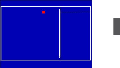
Main Menu
The main menu allows you to select from a list of setup functions together with two exit choices.
Use the arrow keys to select a specific item and press <Enter> to go to the submenu.
CMOS Setup Utility - Copyright (C) 1985-2006, American Megatrends, Inc.
|
►SystemInformationi |
|
► PC Health Status |
|
► Advanced BIOS Features |
► BIOS Security Features |
|
|
► Fox Central Control Unit |
Load Optimal Defaults |
|
|
► Advanced Chipset Features |
Save & Exit Setup |
|
|
► Integrated Peripherals |
Exit Without Saving |
|
|
► Power Management Setup |
|
|
↑↓←→:Move Enter:Select +/-/:Value |
F10:Save ESC:Exit F1:General Help |
||
|
F9:Optimized Defaults |
|
|
Configure Time and Date. Display System Information...
v02.61 (c) Copyright 1985-2006, American Megatrends, Inc.
Each item in the main menu is explained below:
►System Information
It displays the basic system configuration, such as BIOS ID, CPU Name, memory size plus system date, time and Floppy drive. They all can be viewed or set up through this menu.
►Advanced BIOS Features
The advanced system features can be set up through this menu. There are boot up settings.
►Fox Central Control Unit
Some special proprietary features (such as overclocking) can be set up through this menu.
►Advanced Chipset Features
The values for the chipset can be changed through this menu, and the system performance can be optimized.
►Integrated Peripherals
All onboard peripherals can be set up through this menu. There are IDE devices, Super I/O devices such as Serial I/O and other USB devices... etc.
19
|
► Power Management Setup |
|
All the items related with Green function features can be set up through this menu. |
|
► PC Health Status |
|
This setup enables you to read/change Fan speeds, and displays temperatures and voltages |
|
of your CPU/System. |
|
► BIOS Security Features |
|
The Supervisor/User password can be set up through this menu to prevent unauthorized use |
|
of your computer. If you set a password, the system will ask you to key in correct password |
|
before boot or access to Setup. |
|
|
3 |
► Load Optimal Defaults |
The optimal performance settings can be loaded through this menu. However, it may offer bet- |
|
|
ter performance in some ways (such as less I/O cards, less memory ...etc.), still, it may cause |
|
problem if you have more memory or I/O cards installed. It means, if your system loading is |
|
|
|
heavy, set to optimal default may sometimes come out an unstable system. What you need |
|
now is to adjust BIOS setting one by one, trial and error, to find out the best setting for your |
current system.
► Save & Exit Setup
Save setting values to CMOS and exit.
► Exit Without Saving
Do not change anything and exit the setup.
20
System Information
This sub-menu is used to set up the standard BIOS features, such as the date, time, floppy drive and so on. Use the arrow up/down keys to select an item, then use the <+> or <-> keys to change the setting.
CMOS Setup Utility - Copyright (C) 1985-2006, American Megatrends, Inc.
System Information
AMIBIOS |
|
|
|
Help Item |
Date (mm:dd:yy) |
[Mon , 11/27/2009] |
|
|
|
Time (hh:mm:ss) |
[10 : 59 : 49] |
|
Use [Enter], [TAB] |
|
► Primary IDE Master |
[Not Detected] |
|
or [SHIFT-TAB] to |
|
► Primary IDE Slave |
[Not Detected] |
|
select a field. |
|
► Secondary IDE Master |
[Not Detected] |
|
Use [+] or [-] to |
|
► Secondary IDE Slave |
[Not Detected] |
|
||
► Third IDE Master |
[Not Detected] |
|
configure system Date. |
|
► Third IDE Slave |
[Not Detected] |
|
|
|
Halt On |
|
[All Errors But ...] |
|
|
Keyboard |
|
[Disabled] |
|
|
Mouse |
|
[Disabled] |
|
|
Model Name |
|
:A74ML 3 Series |
|
|
BIOS ID |
:9A5F1D04 |
|
|
|
|
|
|||
CPU Name |
:AMD Engineering Sample |
|
|
|
System Memory Size :512MB |
|
|
||
|
|
|||
↑↓←→:Move |
Enter:Select |
+/-/:Value F10:Save |
ESC:Exit F1:General Help |
|
|
|
F9:Optimized Defaults |
|
|
AMIBIOS
►Date (mm:dd:yy)
<weekday><month><date> <year> format.
Day—weekday from Sun. to Sat., this message is automatically displayed by BIOS (Read Only).
Month—month from 1 to 12.
Date—date from 1st to 31st. Year—year, set up by users.
Use [ENTER], [TAB] or [SHIFT-TAB] to select a field. Use [+] or [-] to input the value.
►Time (hh:mm:ss)
This item allows you to configure the desired time. Use [ENTER] to enter the setting, then use [TAB] to move forward a field. Use [+] or [-] to input the value.
The three fields of the setting are <hour> : <minute> : <second> respectively.
►Primary/Secondary/Third IDE Master/Slave
While entering setup, BIOS automatically detects the presence of IDE devices. This item displays the drive information of IDE devices. The display information only applies when SATA Mode Select is set to [IDE] mode.
►Halt On
This category determines whether or not the computer will stop if an error is detected during powering up.
[All Errors] : All errors can result in system halt.
[All Errors But...] : All errors but keyboard or mouse or floppy can result in system halt. The halt condition can be enabled/disabled in the next three settings.
►Keyboard
The system boot will not stop for a keyboard error if you enabled this item.
3
21

|
► Mouse |
|
The system boot will not stop for a mouse error if you enabled this item. |
|
► Model Name |
|
Model name of this product. |
|
► BIOS ID |
|
It displays the current BIOS ID/version. User can check this information and discuss with the |
|
field service people if a BIOS upgrade is needed. |
|
► CPU Name |
|
It displays the current CPU name. |
3 |
► System Memory Size |
This item displays the current memory size. The size is depending on how many memory mod- |
ules were installed in your system before powering on.
► MAC Address
This item shows the onboard LAN MAC address.
22

Advanced BIOS Features
CMOS Setup Utility - Copyright (C) 1985-2006, American Megatrends, Inc.
Advanced BIOS Features
IDE Detect Time Out |
[35] |
|
Help Item |
MPS Revision |
[1.4] |
|
|
PCI Latency Timer |
[64] |
|
Select the time out |
Quiet Boot |
[Enabled] |
value for detecting |
|
Quick Boot |
[Enabled] |
ATA/ATAPI device(s). |
|
Bootup Num-Lock |
[On] |
|
|
3
↑↓←→:Move Enter:Select +/-/:Value F10:Save ESC:Exit F1:General Help
F9:Optimized Defaults
►IDE Detect Time Out
This item is used to select the time out value for detecting ATA/ATAPI devices. If the checking time is over the set value, the system will skip it.
►MPS Revision
This feature is only applicable to multiprocessor motherboards as it specifies the version of the MPS that the motherboard will use. The MPS is a specification by which PC manufacturers design and build CPU architecture systems with two or more processors. MPS 1.1 was the original specification. MPS version 1.4 adds extended configuration tables for improved support of multiple PCI bus configurations and greater expandability in the future. In addition,
MPS 1.4 introduces support for a secondary PCI bus without requiring a PCI bridge. If your operating system comes with support for MPS 1.4, you should keep the setting as the default 1.4. You also need to enable MPS 1.4 support if you need to make use of the secondary PCI bus on a motherboard that doesn't come with a PCI bridge. You should only leave it as 1.1 only if you are running an older operating system that only supports MPS 1.1.
►PCI Latency Timer
This item is used to set the PCI latency timer. The value is in unit of PCI cycle for PCI device latency timer register. Setting values are 32, 64, 96, 128, 160, 192, 224, 248.
This feature controls how long each PCI device can hold the bus before another takes over. The larger the value, the longer the PCI device can retain control of the bus. Low values for the PCI Latency Timer will reduce the effective PCI bandwidth while higher values means every PCI device will have to wait longer before they can get access to the bus, but when they do get access, they can conduct their transactions for a longer time. Normally, a default value of 64 cycles is set. Some PCI devices may not agree with longer latency times so if you start facing problems like stuttering sound or a less responsive system, reduce the latency. Higher values will actually reduce performance as too much time may be allocated to each PCI device to the disadvantage of other devices on the bus.
►Quiet Boot
This item is used to enable/disable the quiet boot.
23
 Loading...