


NETBOX User’s Manual

Trademark:
All trademarks are the property of their respective owners.
Version:
User’s Manual V1.2 for NETBOX.
Symbol description:
|
|
|
T |
I O |
N |
! |
Caution : refers to important information that can help you to use NETBOX |
|
|
U |
|
||||
C |
A |
|
|
|
|
||
|
|
|
|
better, and tells you how to avoid problems. |
|||
|
|
|
|
|
RoHS
This product has been designed and manufactured in compliance with Directive 2002/95/EC of the European Parliament and the Council on restriction of the use of certain hazardous substances in electrical and electronic equipment (RoHS Directive) and is deemed to comply with the maximum concentration values issued by the European Technical Adaptation Committee (TAC) as shown below:
Substance |
Proposed Maximum Concentration |
Actual Concentration |
|
|
|
|
|
Lead (Pb) |
0,1% |
< 0,1% |
|
|
|
|
|
Mercury (Hg) |
0,1% |
< 0,1% |
|
|
|
|
|
Cadmium (Cd) |
0,01% |
< 0,01% |
|
|
|
|
|
Hexavalent Chromium (Cr6+) |
0,1% |
< 0,1% |
|
|
|
|
|
Polybrominated biphenyls (PBB) |
0,1% |
< 0,1% |
|
|
|
|
|
Polybrominated diphenyl ethers |
0,1% |
< 0,1% |
|
(PBDE) |
|||
|
|
Certain components of products as stated above are exempted under the Annex of the RoHS
Directives as noted below:
Examples of exempted components are:
1.Mercury in compact fluorescent lamps not exceeding 5 mg per lamp and in other lamps not specifically mentioned in the Annex of RoHS Directive.
2.Lead in glass of cathode ray tubes, electronic components, fluorescent tubes, and electronic ceramic parts (e.g. piezoelectronic devices).
3.Lead in high temperature type solders (i.e. lead-based alloys containing 85% by weight or more lead).
4.Lead as an allotting element in steel containing up to 0.35% lead by weight, aluminium containing up to 0.4% lead by weight and as a cooper alloy containing up to 4% lead by weight.
CAUTION: RISK OF EXPLOSION IF BATTERY IS REPLACED BY AN INCORRECT TYPE DISPOSE OF USED BATTERIES ACCORDING TO THE INSTRUCTIONS
© All rights reserved.
All trade names are registered trademarks of respective manufacturers listed.
All images are for reference only, please refer to the physical product for specific features.

Statement:
This device complies with part 15 of the FCC Rules. Operation is subject to the following two conditions: (1) This device may not cause harmful interference, and (2) this device must accept any interference received, including interference that may cause undesired operation.
Warning:
FEDERAL COMMUNICATIONS COMMISSION INTERFERENCE STATEMENT
This equipment has been tested and found to comply with the limits for a Class B digital device, pursuant to part 15 of the FCC Rules. These limits are designed to provide reasonable protection against harmful interference in a residential installation. This equipment generates, uses and can radiate radio frequency energy and, if not installed and used in accordance with the instructions, may cause harmful interference to radio communications. However, there is no guarantee that interference will not occur in a particular installation. If this equipment does cause harmful interference to radio or television reception, which can be determined by turning the equipment off and on, the user is encouraged to try to correct the interference by one or more of the following measures:
▪Reorient or relocate the receiving antenna.
▪Increase the separation between the equipment and receiver.
▪Connect the equipment into an outlet on a circuit different from that to which the receiver is connected.
▪Consult the dealer or an experienced radio/ TV technician for help.
Caution:
Any changes or modifications not expressly approved by the grantee of this device could void the user’s authority to operate the equipment.
CE Conformity for European Countries
The device complies with the EMC Directive 2004/108/EC and Low Voltage Directive
2006/95/EC.
Following information is only for EU-member states:
The mark shown to the right is in compliance with the Waste Electrical and
Electronic Equipment Directive 2002/96/EC (WEEE).
The mark indicates the requirement NOT to dispose the equipment as unsorted municipal waste, but use the return and collection systems according to local law.
If the batteries, accumulators and button cells included with this equipment, display the chemical symbol Hg, Cd, or Pb, then it means that the battery has a heavy metal
content of more than 0.0005% Mercury or more than, 0.002% Cadmium, or more than 0.004% Lead.

RF exposure warning:
This equipment must be installed and operated in accordance with provided instructions and the antenna(s) used for this transmitter must be installed to provide a separation distance of at least 20 cm from all persons and must not be co-located or operating in conjunction with any other antenna or transmitter. End-users and installers must be provide with antenna installation instructions and transmitter operating conditions for satisfying RF exposure compliance.
R&TTE Compliance Statement
This wireless module device complies with the Essential Requirements of the R&TTE Directive of the European Union (1999/5/EC). This equipment meets the following conformance standards:
ETSI EN 300 328
EN 301 489-01
EN 301 489-17
Notified Countries: Germany, UK, Netherlands, Belgium, Sweden, Denmark, Finland, France, Italy, Spain, Austria, Ireland, Portugal, Greece, Luxembourg, Estonia, Latvia,
Lithuania, Czech Republic, Slovakia, Slovenia, Hungary, Poland and Malta.

Safety Notice :
|
|
|
TI |
O |
N |
|
|
U |
|
||
|
A |
|
|
||
C |
|
|
|
||
|
|
|
|
||
|
|
|
|
|
!
Before using this product, please read the below safety notice carefully, this will help to extend the product’s lifecycle, and work normally.
■When NETBOX is working, please make sure its ventilation system is working.
■The power adapter is dissipating heat during normal use, please be sure not to cover it and keep it away from your body to prevent discomfort or injury by heat exposure.
■Please use the power adapter that comes with the product’s package, wrong power adapter may damage your device.
■Make sure all the peripherals are properly connected before using NETBOX.
■This product should only be used in an environment with ambient temperatures between 0◦C and 40◦C.
■To reduce the risk of fire, use only No. 26 AWG or larger UL listed or CSA certified telecommunication line cord.
■Always shut down the computer before installing or uninstalling the peripheral which does not support hot plug.
■Disconnect all peripherals before servicing or disassembling this equipment.
■Please do not disassemble this product by yourself, any disassembly not approved by the original manufacturer may result in malfunction, and void warranty.
■Risk of explosion if battery is replaced by an incorrect type, please dispose of used batteries according to the instructions.

Table of Contents |
|
Chapter 1 Introducing the NETBOX |
|
Top View................................................................................................... |
2 |
Front Side View......................................................................................... |
2 |
Back Side View......................................................................................... |
3 |
Bottom View.............................................................................................. |
3 |
LED Indicator Introduction........................................................................ |
4 |
Chapter 2 Placing and connecting the NETBOX |
|
Placement of NETBOX |
|
On the Desk.......................................................................................... |
6 |
On the Display Back............................................................................. |
6 |
Connection of NETBOX |
|
Connect the Antenna............................................................................ |
8 |
Connect the Monitor.............................................................................. |
8 |
Connect the USB Devices.................................................................... |
8 |
Connect the Network Cable.................................................................. |
9 |
Connect the Power Cord....................................................................... |
9 |
Chapter 3 BIOS Setup |
|
Main Menu.............................................................................................. |
11 |
Advanced Menu...................................................................................... |
11 |
Exit Menu................................................................................................ |
13 |
Chapter 4 Install Windows 7 in NETBOX |
|
Install Windows 7.................................................................................... |
15 |
Install Drivers in Windows 7.................................................................... |
19 |
Chapter 5 FoxOS Introduction |
|
First Boot................................................................................................. |
21 |
Desktop................................................................................................... |
23 |
Internet Connection................................................................................. |
25 |
“Help” Introduction.................................................................................. |
29 |
Recover FoxOS 3.0 Home...................................................................... |
30 |

The NETBOX is a compact and easy to use desktop. It features all the desktop capabilities but with a slim body design which enables your to browse the internet in a relax and comfortable way.
This chapter introduces NETBOX’s outlook :
■Top View
■Front Side View
■Back Side View
■Bottom View
■LED Indicator Introduction

1
Introduction
NETBOX features all the desktop capabilities but with a slim body design which enables you to browse the internet in a relaxable and comfortable way.
1-1 Top View
190mm
135mm
1-2 Front Side View
|
25mm |
|
|
|
|
|
|
1 |
2 |
3 |
4 LLS_LED1 5 LLS_LED5 6 |
7 |
8 |
No. |
Name |
|
|
Description |
|
|
1 |
Headphone Port |
|
Connects to a headphone |
|
|
|
2 |
Microphone In and S/PDIF In |
Connects to a microphone or playback devices with |
||||
|
Port |
|
|
optical connectors(3.5mm jack) |
|
|
3 |
Multi-Function Card Reader |
Support SD/SDHC/MS/MS Pro/MMC memory cards |
||||
4 |
USB Ports |
|
|
Connect to USB devices |
|
|
5 |
LLS_LED |
|
|
Indicate different system state |
|
|
6 |
HDD_LED |
|
|
Indicates hard disk states |
|
|
7 |
Suspend Button |
|
Enter suspend mode in operating system |
|||
8 |
Power Button with |
|
Turning the power on/off, Indicates system states |
|||
|
Integrated LED Indicator |
|
|
|
||
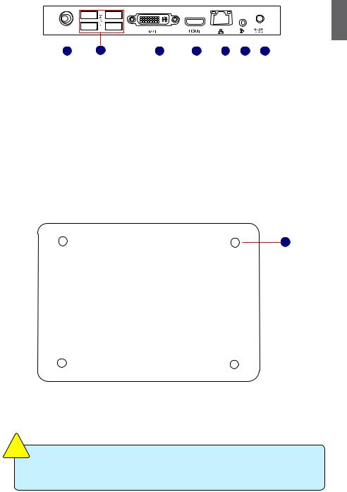
1-3 Back Side View
1
|
|
|
2 |
|
|
|
|
|
|
|
|
|
|
|
|
|
|
|
|
|
|
|
|
|
|
|
|
|
|
|
|
|
|
|
|
|
|
|
|
|
|
|
|
|
|
1 |
3 |
4 |
5 |
6 |
7 |
||||||||
|
|
|
|
|
|
|
|
|
|
|
|
|
|
|
No. |
Name |
|
Description |
|
|
|
|
|
|
|
|
|
||
1 |
RF(Radio Frequency) Port |
Connects to antenna |
|
|
|
|
|
|
|
|||||
2 |
USB Ports |
|
Connects to USB devices |
|
|
|
|
|
||||||
3 |
Display Output Port |
Connects to display device |
|
|
|
|
|
|||||||
4 |
HDMI Port |
|
Connects to HDMI audio and video |
|||||||||||
|
|
|
|
|
|
|
|
|
|
|
|
|||
5 |
Network Port |
|
Standard RJ-45 network port |
|
|
|
||||||||
6 |
Line Out and S/PDIF Out Port |
Connects to powered analog speakers or record- |
||||||||||||
|
|
|
|
ing devices with optical connectors(3.5mm jack) |
||||||||||
7 |
Power Input Port |
Connects to the power adapter |
|
|
|
|||||||||
1-4 Bottom View
1
No. |
Name |
Description |
1 |
Sheet Metal |
NETDVD(optional accessary) or Magnet-Metal-Feet can mag- |
|
|
netize them to seat firmly |
|
|
|
T |
I |
O |
N |
|
|
U |
|
|||
|
A |
|
|
|
||
C |
|
|
|
|
||
|
|
|
|
|
||
|
|
|
|
|
|
!
There are four Magnet-Metal-Feet in the package. Just align them to the sheet metal on the bottom, then they can magnetize the NETBOX easily. The feet can seat and protect NETBOX when it is placed on the tabletop.

1-5 LED Indicator Introduction
|
|
|
|
|
|
|
|
|
|
|
|
|
|
|
|
1 |
|
|
|
|
|
|
|
Indication |
Power_ |
HDD_ |
LLS_ |
LLS_ |
LLS_ |
LLS_ |
LLS_ |
|
|
|
|
|
|
|
|
LED |
LED |
LED1 |
LED2 |
LED3 |
LED4 |
LED5 |
|
|
|
|
|
|
|
|
|
|
|||||||
|
|
|
|
|
|
|
|
|
|
|
|
|
|
|
|
|
|
|
|
|
|
|
|
S0(Working Mode) |
Green |
- |
Off |
Off |
Off |
Off |
Off |
|
|
|
|
|
|
|
|
|
|
|
|
|
|
|
|
|
|
|
|
|
|
|
|
S1(Power-Saving Mode) |
Green |
Off |
Off |
Off |
Off |
Off |
Off |
|
|
|
|
|
|
|
|
|
|
|
|
|
|
|
|
|
|
|
|
|
|
|
|
S3(Standby Mode) |
Red |
Off |
Off |
Off |
Off |
Off |
Off |
|
|
|
|
|
|
|
|
|
|
|
|
|
|
|
|
|
|
|
|
|
|
|
|
S4(Hibernation Mode) |
Red |
Off |
Off |
Off |
Off |
Off |
Off |
|
|
|
|
|
|
|
|
&S5(System Power Off Mode) |
|
|
|
|
|
|
|
|
|
|
|
|
|
|
|
|
|
|
|
|
|
|
|
|
|
|
|
|
|
|
|
CPU |
- |
- |
Blue, |
- |
- |
- |
- |
|
|
|
|
|
|
|
|
Initialization Error |
|
|
Blink |
|
|
|
|
|
|
|
|
|
|
|
|
|
|
|
|
|
|
|
|
|
|
|
|
|
|
|
|
DRAM Error |
- |
- |
- |
Blue, |
- |
- |
- |
|
|
|
|
|
|
|
|
|
|
|
|
Blink |
|
|
|
|
|
|
|
|
|
|
|
|
|
|
|
|
|
|
|
|
|
|
|
|
|
|
|
BIOS Boot Block Fail |
- |
- |
- |
- |
- |
Blue, |
- |
|
|
|
|
|
|
|
|
|
|
|
|
|
|
Blink |
|
|
|
|
|
|
|
|
|
|
|
|
|
|
|
|
|
|
|
|
|
|
|
|
|
BIOS |
- |
- |
- |
- |
- |
- |
Blue, |
|
|
|
|
|
|
|
|
Checksum Error |
|
|
|
|
|
|
Blink |
|
|
|
|
|
|
|
|
|
|
|
|
|
|
|
|
|
|
|
|
|
|
|
|
CMOS Cleared |
Red, |
- |
- |
- |
- |
- |
- |
|
|
|
|
|
|
|
|
|
Blink |
|
|
|
|
|
|
|
|
|
|
|
|
|
|
|
|
|
|
|
|
|
|
|
|
|
|
|
|
|
|
HDD R/W Data |
- |
Red |
- |
- |
- |
- |
- |
|
C |
|
|
T |
I O |
N |
! |
|
|
|
|
|
|
|
|
|
|
U |
|
|
|
|
|
|
|
|
|
||||
|
|
A |
|
|
|
|
|
|
|
|
|
|
|
||
|
|
|
|
|
|
|
|
|
|
|
|
|
|
||
|
|
|
|
|
|
|
|
|
|
|
|
|
|
|
The LLS_LEDs status in this table only show BIOS error message.
In this chapter, the placement and the connection of some necessary peripherals will be introduced.
This chapter includes the following information:
■Placement of NETBOX
■Connection of NETBOX

2-1 Placement of NETBOX
1.On the Desk
1.You can install your NETBOX in the mount like the right image.
2
2.If there is enough space on your desk, you can simply put your NETBOX on the tabletop as shown below.
2. On the Display Back
This is the best space-saving way.
1. Use four screws to fasten the bracket onto the display back.
|
|
|
T |
I |
O |
N |
|
|
U |
|
|||
|
A |
|
|
|
||
C |
|
|
|
|
||
|
|
|
|
|
||
|
|
|
|
|
|
!
To install this bracket, your display must follow VESA75/VESA100 standard. The two groups of holes on your dispaly have different space between, and they help you easily fasten the bracket onto your display.

2. Fit the NETBOX into the bracket with power button locating at the top for easy touch.
2
2
1
3. After that, you can connect the antenna to your NETBOX.
|
|
|
T |
I |
O |
N |
|
|
U |
|
|||
|
A |
|
|
|
||
C |
|
|
|
|
||
|
|
|
|
|
||
|
|
|
|
|
|
!
Remove the antenna and lift up the NETBOX straightly to take it out.
 Loading...