


 Loading...
NanoPC


 User’s Manual

Trademark:
All trademarks are the property of their respective owners.
Version:
User’s Manual V1.1 for NanoPC.
Symbol description:
C
|
U |
T |
I O |
A |
|
||
|
|
||
|
|
|
N
Note: |
Refers to important information that can help you to use NanoPC better, and |
|
tells you how to avoid problems. |
Caution: Indicating a potential risk of hardware damage or physical injury may exist.
WEEE:
The use of this symbol indicates that this product may not be treated as household waste. By ensuring this product is disposed of correctly, you will help prevent potential negative consequences for the environment and human health, which could otherwise be caused by inappropriate waste handling of this product. For more detailed information about recycling of this product, please contact your local city office, your household waste disposal service or the shop where you purchased this product.
© All rights reserved.
All trade names are registered trademarks of respective manufacturers listed.
All images are for reference only, please refer to the physical product for specific features.

Safety Notice:
C
AU |
T |
I O |
|
||
|
|
N
Before using this product, please read the below safety notice carefully, this will help to extend the product’s lifecycle, and work normally.
■When NanoPC is working, please make sure its ventilation system is working.
■The power adapter is dissipating heat during normal use, please be sure not to cover it and keep it away from your body to prevent discomfort or injury by heat exposure.
■Please use the power adapter that comes with the product’s package, wrong power adapter may damage your device.
■Make sure all the peripherals are properly connected before using NanoPC.
■This product should only be used in an environment with ambient temperatures between 0°C and 40°C.
■Always shut down the computer before installing or uninstalling the peripheral which does not support hot plug.
■Disconnect all peripherals before servicing or disassembling this equipment.
■Please do not disassemble this product by yourself, any disassembly not approved by the original manufacturer may result in malfunction, and void warranty.
■Risk of explosion if battery is replaced by an incorrect type, please dispose of used batteries according to the instructions.
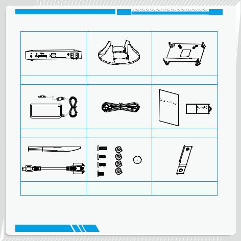
Package Contents
NanoPC |
Seat Base |
VESA Mount |
||
|
|
|
|
|
|
|
|
|
|
Power Adapter |
Power Cord |
Easy Guide, USB Flash Disk |
Opening Tool |
Screws, Magnet Rubber Foot, |
Mini PCIe Half Card Support |
|
Mini COM to COM cable (Optional) |
Screws cover |
||
|

TABLE OF CONTENTS |
|
Introduction |
|
1-1 Front Side View....................................................................................................... |
2 |
1-2 Back Side View....................................................................................................... |
4 |
1-3 DDR3/DDR3L jumper.............................................................................................. |
6 |
Placement and connecting |
|
2-1 Placement of NanoPC............................................................................................ |
8 |
In Seat Base.............................................................................................................. |
8 |
On the desk............................................................................................................... |
8 |
Installing to Display................................................................................................... |
9 |
2-2 Connection of NanoPC........................................................................................ |
10 |
Connect display....................................................................................................... |
10 |
Connect USB devices............................................................................................. |
11 |
Connect network cable............................................................................................ |
11 |
Connect power cord................................................................................................ |
12 |
Connect Point Of Sales........................................................................................... |
13 |
BIOS Setup |
|
Enter BIOS Setup........................................................................................................ |
15 |
Main............................................................................................................................. |
17 |
F-center....................................................................................................................... |
18 |
Smart BIOS............................................................................................................. |
19 |

Fox Intelligent Stepping........................................................................................... |
20 |
CPU Configuration.................................................................................................. |
21 |
Advanced.................................................................................................................... |
23 |
Trusted Computing.................................................................................................. |
24 |
North Bridge............................................................................................................ |
25 |
TXE Subsystem...................................................................................................... |
26 |
Onboard Device Configuration................................................................................ |
27 |
SATA Configuration................................................................................................. |
28 |
Super IO Configuration........................................................................................... |
29 |
Network Stack Configuration................................................................................... |
30 |
Boot............................................................................................................................. |
31 |
CSM parameters.................................................................................................... |
32 |
Power.......................................................................................................................... |
33 |
Health.......................................................................................................................... |
34 |
Security....................................................................................................................... |
35 |
Save & Exit.................................................................................................................. |
36 |
Install OS |
|
4-1 Install Windows 8.1/Windows 8/Windows 7(64 bit)............................................... |
39 |
4-2 Install Drivers........................................................................................................ |
43 |
Utility |
|
Fox WINFLASH........................................................................................................... |
45 |
1. Local Update....................................................................................................... |
45 |
2. About & Help....................................................................................................... |
47 |
Introduction
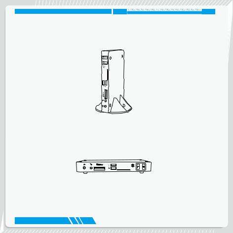
INTRODUCTION
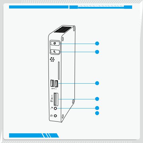
1-1 Front Side View
1
2
3
4
5  6
6
2

INTRODUCTION
1 |
Power button with Power indicator LED |
|
Press to turn your NanoPC on or off, the LED can indicate your system |
|
states. |
2 |
Suspend Button |
|
Enter suspend mode in operating system. |
|
Clear CMOS : Press Suspend Button 10s in S5. |
3 |
USB 3.0 port |
|
This USB port supports the USB 3.0/2.0/1.0 specification. Use this port for |
|
USB devices such as keyboard, mouse, USB printer, USB flash drives and |
|
hard disk drives, etc. |
4 |
Multi-Function card reader |
|
This memory card reader supports MS/MS Pro SD/SDHC/SDXC/MMC |
|
memory cards used in devices like digital cameras, mobile phones, Media |
|
players and so on. |
5 |
Microphone |
|
Connects to a microphone or playback devices with optical connectors |
|
(3.5mm jack). |
6 |
Headphone |
|
Connects to a headphone. |
3

INTRODUCTION
1-2 Back Side View
1
2
3
4
5
6
7
8
4
INTRODUCTION
1 |
COM |
COM port |
|
|
Use this port for devices such as Point Of Sales. |
|
|
Connect Point Of Sales that uses Mini COM to COM cable to this port. |
2 |
|
USB 2.0 port |
|
|
This USB port supports the USB 2.0/1.0 specification. Use this port for USB |
|
|
devices such as keyboard, mouse, USB printer, USB flash drives and hard |
|
|
disk drives, etc. |
3 |
VGA |
VGA Port |
|
|
Connect VGA-compatible displays such as a monitor or projector. |
4 |
HDMI |
HDMI port |
|
|
The HDMI (High-Definition Multimedia Interface) port supports Full-HD |
|
|
display devices. |
|
|
Connect monitor or TV that uses HDMI connector to this port. |
5Kensington lock
Attach a Kensington security system or a compatible security lock to secure your NanoPC in place.
6 |
RJ-45 LAN port |
|
Supports 10/100/1000Mb/s Ethernet network. |
|
Connect network cable to access Internet. |
7 |
Line out |
|
Connects to powered analog speakers or recording devices with optical |
|
connectors (3.5mm jack). |
8 |
Power input port |
|
Connect power cord that come with your product. |
5

INTRODUCTION
1-3 DDR3/DDR3L jumper
Set the jumper to pins 1-2, it set to DDR3L, the DDR3L Power is 1.35V.
Set the jumper to pins 2-3, it set to DDR3, the DDR3 Power is 1.5V.
|
1 |
1.35V |
2 |
|
3 |
|
1 |
1.5V |
2 |
|
3 |
6
Placement and connecting
■Placement of NanoPC
■Connection of NanoPC
PLACEMENT AND CONNECTING
2-1 Placement of NanoPC
In Seat Base
1. Place your NanoPC into the groove of the Seat Base.
On the desk
1. Fit your NanoPC with Magnet Rubber Foot, and put it on the tabletop directly.
8

PLACEMENT AND CONNECTING
Installing to Display
This is the best space-saving way.
1. Use four screws to fasten the Vesa Mount onto the display back.
2. Fit the Nettop into the Vesa Mount with power button locating at the top for easy touch.
2
1
To fasten the VESA mount, your display must comply with VESA75 or VESA100 standard. The two groups of holes on your display have different space between, and they help you easily fasten the bracket onto your display.
9

PLACEMENT AND CONNECTING
2-2 Connection of NanoPC
Connect display
Connect a display or TV that has HDMI port or VGA port to your NanoPC.
10

PLACEMENT AND CONNECTING
Connect USB devices
Connect USB devices to the USB ports, for example, mouse, keyboard devices.
Connect network cable
Connect one end of a network cable to the RJ-45 LAN port, and the other end to a hub or switch.
11
Loading...