


865M01-G-6ELS

Statement:
This manual is the intellectual property of Foxconn, Inc. Although the
information in this manual may be changed or modified at any time,
Foxconn does not obligate itself to inform the user of these changes.
Trademark:
All trademarks are the property of their respective owners.
®
and Pentium® are registered trademarks of Intel Corporation.
Intel
PS/2 and OS/2 is the registered trademarks of IBM, Inc.
Windows® 95/98/2000/NT/XP is the registered trademark of Microsoft.
®
Award
is the registered trademark of Award, Inc.
Version:
User’s Manual V1.3 in English for 865M01 series motherboard.
P/N:91-181-613-14-42
Symbol description:
Note: refers to important information that can help you to use motherboard
better.
Attention: indicates that it may damage hardware or cause data loss,
and tells you how to avoid such problems.
Warning: means that a potential risk of property damage or physical
injury exists.
More information:
If you want more information about our products, please visit Foxconn’s
website: www.foxconnchannel.com
865M01-English preface-v1.3-121603.p65 2004-5-27, 18:101

Item Checklist:
Thank for your purchasing Foxconn’s 865M01 series motherboard. Please check
the package; if there are missing or damaged items, contact your distributor as
soon as possible.
865M01 series motherboard (x1)
Foxconn Utility CD (x1)
User’s Manual (x1)
IDE Ribbon cable (x1)
FDD Ribbon cable (x1)
I/O Shield (x1)
S-ATA Signal Cable (x1) (optional)
S-ATA Power Cable (x1) (optional)
SPDIF Cable (x1) (optional)
USB 2.0 Cable (x1) (optional)
865M01-English preface-v1.3-121603.p65 2004-5-27, 18:102
Declaration of conformity
HON HAI PRECISION INDUSTRY COMPANY LTD
66 , CHUNG SHAN RD., TU-CHENG INDUSTRIAL DISTRICT,
TAIPEI HSIEN, TAIWAN, R.O.C.
declares that the product
Motherboard
865M01 G/PE/GV series
is in conformity with
(reference to the specification under which conformity is declared in
accordance with 89/336 EEC-EMC Directive)
EN 55022/A1: 2000 Limits and methods of measurements of radio disturbance
characteristics of information technology equipment
EN 61000-3-2/A14:2000 Electromagnetic compatibility (EMC)
Part 3: Limits
Section 2: Limits for harmonic current emissions
(equipment input current <= 16A per phase)
EN 61000-3-3/A1:2001 Electromagnetic compatibility (EMC)
Part 3: Limits
Section 2: Limits of voltage fluctuations and flicker in low-voltage
supply systems for equipment with rated current <= 16A
EN 55024/A1:2001 Information technology equipment-Immunity characteristics limits
and methods of measurement
Signature : Place / Date : TAIPEI/2003
Printed Name : James Liang Position/ Title : Assistant President
865M01-English preface-v1.3-121603.p65 2004-5-27, 18:103

Declaration of conformity
Trade Name: Foxconn
Model Name:
Responsible Party: PCE Industry Inc.
Address: 458 E. Lambert Rd.
Telephone: 714-738-8868
Facsimile: 714-738-8838
Equipment Classification: FCC Class B Subassembly
Type of Product: Motherboard
Manufacturer: HON HAI PRECISION INDUSTRY
Address: 66 , CHUNG SHAN RD., TU-CHENG
865M01 G/PE/GV
Fullerton, CA 92835
COMPANY LTD
INDUSTRIAL DISTRICT, TAIPEI HSIEN,
TAIWAN, R.O.C.
Supplementary Information:
This device complies with Part 15 of the FCC Rules. Operation is subject to the follow-
ing two conditions : (1) this device may not cause harmful interference, and (2) this
device must accept any interference received, including interference that may cause
undesired operation.
Tested to comply with FCC standards.
Signature : Date : 2003
865M01-English preface-v1.3-121603.p65 2004-5-27, 18:104

Table of Contents
Chapter
Main Features .............................................................................................. 2
865M01 Layout ............................................................................................ 5
Chapter
CPU ............................................................................................................. 11
Memory ...................................................................................................... 16
Power Supply ............................................................................................ 21
Rear Panel Connectors .............................................................................. 22
Other Connectors ...................................................................................... 24
Expansion Slots ......................................................................................... 34
Jumpers ..................................................................................................... 37
Chapter
Enter BIOS Setup ....................................................................................... 42
Main menu ................................................................................................. 42
Standard CMOS Features ........................................................................... 44
BIOS Features Setup .................................................................................. 47
Advanced BIOS Features Setup ................................................................. 48
Advanced Chipset Features Setup ............................................................. 51
Integrated Peripherals ................................................................................. 53
Power Management Setup ......................................................................... 58
PnP/PCI Configuration ............................................................................... 61
PC Health Status ........................................................................................ 62
Frequency/Voltage Control ......................................................................... 63
Load Fail-Safe Defaults .............................................................................. 64
Load Optimized Defaults ............................................................................. 64
Set Supervisor/User Password ................................................................... 64
Save & Exit Setup ...................................................................................... 65
Exit Without Saving .................................................................................... 65
1
1
2
2
3
3
Product Introduction
Installation Instructions
BIOS Description
865M01-English preface-v1.3-121603.p65 2004-5-27, 18:105

Table of Contents
Chapter
Utility CD content ........................................................................................ 67
Start to install driver ................................................................................... 68
Install Chipset Software ............................................................................. 68
Install DirectX ............................................................................................. 69
Install VGA Driver (optional) ....................................................................... 70
Install USB2.0 Driver .................................................................................. 71
Using 4-/6-channel Audio ........................................................................... 71
Install LAN Driver (optional) ....................................................................... 78
Install Norton Internet Security 2004 .......................................................... 79
Chapter
SuperStep ................................................................................................. 81
SuperLogo ................................................................................................. 84
SuperUpdate .............................................................................................. 86
Chapter
SuperSpeed ............................................................................................... 92
SuperBoot .................................................................................................. 93
SuperBIOS-Protect ..................................................................................... 94
SuperRecovery .......................................................................................... 95
4
4
5
5
6
6
Driver CD Introduction
Directions for Bundled Software
Special BIOS Functions
865M01-English preface-v1.3-121603.p65 2004-5-27, 18:106

Warning:
1. Attach the CPU and heatsink using silica gel to ensure full contact.
2. It is suggested to select high-quality, certified fans in order to avoid
damage to the motherboard and CPU due high temperatures.
3. Never turn on the machine if the CPU fan is not properly installed.
4. Ensure that the DC power supply is turned off before inserting or
removing expansion cards or other peripherals, especially when
you insert or remove a memory module. Failure to switch off the DC
power supply may result in serious damage to your system or
memory module.
Warning:
We cannot guarantee that your system will operate normally while
over-clocked. Normal operation depends on the over-clock capacity
of your device.
Attention:
Since BIOS programs are upgraded from time to time, the BIOS
description in this manual is just for reference. We do not guarantee
that the content of this manual will remain consistent with the actual
BIOS version at any given time in the future.
Attention:
The pictures of objects used in this manual are just for your reference.
Please refer to the physical motherboard.
865M01-English preface-v1.3-121603.p65 2004-5-27, 18:107

This page is intentionally left blank
865M01-English preface-v1.3-121603.p65 2004-5-27, 18:108

Chapter
1
1
Thank you for buying Foxconn’s 865M01 series
motherboard. This series of motherboard is one of our new
products, and offers superior performance, reliability and
quality, at a reasonable price. This motherboard adopts the
advanced Intel® 865 G/PE/GV+ICH5/5R chipset, providing us-
ers a computer platform with a high integration-compatibility-per-
formance price ratio.
This chapter includes the following information:
Main Features
865M01 Layout

Chapter 1 Product Introduction
Main Features
Size
mATX form factor of 9.6 inch x 9.1 inch
Microprocessor
Supports Intel® Pentium®4 socket 478 (Willamette/Northwood/Prescott)
processors
Supports Intel® Celeron® socket 478 (Willamette/Northwood) processors
Supports FSB at 400MHz/533MHz/800MHz
Support Hyper-threading technology
Chipset
Intel® Springdale chipset: Intel 865G/PE/GV (NorthBridge) + ICH5/5R
(SouthBridge)
System Memory
Two 184-pin DIMM slots
Supports PC3200/2700/2100 memory
Supports 128/256/512 Mb technology up to 2GB
Supports Dual-channel DDR
Attention:
1. Use the same memory modules for Dual-channel.
2. The memory operating frequency is 320MHz while FSB800
CPU works with DDR333.
USB 2.0 Ports:
Supports hot plug
Eight USB 2.0 ports (four rear panel ports, two onboard USB headers
providing four extra ports)
Supports wake-up from S1 and S3 mode
Supports USB 2.0 Protocol up to 480 Mbps transmission rate
2
865M01G/PE/GV User Manual

Chapter 1 Product Introduction
Onboard Serial ATA
150MBps transfer rate
Supports two S-ATA devices, such as HDD, etc.
Onboard 1394 (Optional)
Support hot plug
With rate of transmission at 400Mbps
Self-configured addressing
Can connect with 2 independent 1394 units synchronously at most, such
as HDD, CD-ROM
Onboard LAN (Optional)
Supports 10/100Mbit/sec Ethernet
10/100M LAN interface built-in on board
Onboard Audio
AC’ 97 2.3 Specification Compliant
Supports S/PDIF output/input
Onboard Line-in jack, Microphone-in jack, Line-out jack
Supports 5.1 channels audio (setting via software)
Onboard Graphics
Supports integrated VGA display functions (Intel Extreme Graphics)
(supported on 865M01G/GV only)
Supports external AGP3.0/2.0 specification; supports 4X/8X display cards
(supported on 865M01G/PE only)
BIOS
Licensed advanced AWARD (Phoenix) BIOS, supports flash ROM, plug-and-
play
Supports IDE, CD-ROM, SCSI HDD and USB device boot up
865M01G/PE/GV User Manual
3
Chapter 1 Product Introduction
Green Function
Supports ACPI (Advanced Configuration and Power Interface)
Supports five system modes---- S0 (normal), S1 (power on suspend), S3
(suspend to RAM), S4 (Suspend to disk - depends on OS), and S5 (soft - off).
Expansion Slots
Three PCI slots
One AGP slot (supported on 865M01 G/PE only)
AGP 8X support:
AGP 8X (AGP 3.0) is the VGA interface specification that enabled enhanced
graphics performance with high handwidth speeds up to 2.12 GB/s.
Advanced Features
PCI 2.2 Specification Compliant
Supports Windows 98/2000/ME/XP soft-off
Supports Wake-on-LAN, Wake-on Modem function
Supports PC Health function (capable of monitoring system voltage, CPU,
system temperature, and fan speed)
4
865M01G/PE/GV User Manual

865M01 Layout
Chapter 1 Product Introduction
16
15
14
1
3 42
5
6
7
8
9
10
12 1113
865M01G/PE/GV User Manual
5

Chapter 1 Product Introduction
ATX 12V connector
1
This power connector connects the 4-pin 12V plug from the ATX 12V power
supply.
2
CPU socket
A 478-pin surface mount, Zero Insertion Force (ZIF) Socket for the intel
Pentium® 4 processor (and Intel’s future Prescott CPU) Supports 800/533/
400 MHz system bus and allows up to 6.4GB/s data transfer rates.
3
North bridge controller
The Intel® 865G/GV Graphics Memory Controller Hub(GMCH) and the Intel
865PE Memory Controller Hub(MCH) provide the processor interface with
800/533/400 MHz frequency, system memory interface at 400/333/266MHz
operation, and 1.5V AGP interface that supports AGP 3.0 specification including
8X Fast Write protocol, the GMCH provides an integrated graphics accelerator.
4
DDR DIMM sockets
These two 184-pin DIMM sockets support up to 2GB system memory using
unbuffered non-ECC PC3200/2700/2100 DDR DIMMs.
®
®
5
Super I/O
The Winbond W83627HF Low Pin Count (LPC) interface provides the
commonly used Super I/O functionality. The chip supports a high-performance
floppy disk controller for a 360k/720K/1.44M/2.88M floppy disk drive, a multi-
mode parallel port, two serial ports, the mouse and keyboard interface and
the LPC (Low Pin Count) interface.
6
Floppy disk connector
This connector accommodates the provided ribbon cable for the floppy disk
drive. One side of the connector is slotted to prevent incorrect insertion of the
floppy disk cable.
7
ATX power connector
This 20-pin connector connects to an ATX power supply. The power supply
must have at least 1A on the +5V standby lead (+5VSB).
6
865M01G/PE/GV User Manual

Chapter 1 Product Introduction
8
IDE connectors
These 2-channel bus master IDE connectors support Ultra DMA 100/66/33,
PIO Modes 3 & 4 IDE devices. Both the primary (blue)and secondary (white)
connectors are slotted to prevent incorrect insertion of the IDE ribbon cable.
9
AGP slot
This Accelerated Graphics Port (AGP) slot supports 1.5V AGP8X mode graphic
card for 3D graphical applications.
10
Serial ATA connectors
These two 7-pin connectors accommodate the thin cables for Serial ATA
devices.
11
Flash ROM
This 4Mb flash ROM contains the programmable BIOS program.
12
South bridge
The Intel ICH5/5R are subsystem that integrate various I/O functions including
2-channel ATA100 bus master IDE controller, SATA RAID controller (Supported
by ICH5R only), up to eight USB 2.0/1.1 ports, I/O APIC ,AC’97 2.3 interface,
and PCI 2.2 interface.
13
PCI Slots
These three 32-bit PCI 2.2 expansion slots support bus master PCI cards
like SCSI or LAN cards with 133MB/s maximum throughput.
14
1394 controller (optional)
VT6307 is the controller for IEEE1394a on Motherboard. The VT6307 is a
complete small package single chip PCI solution at 400Mbps, low power
seamless plug and play connections to the latest IEEE 1394 enabled devices.
15
10/100M LAN controller (optional)
The RTL8101L is a single-chip solution for LAN On Motherboard (LOM)
applications. The RTL8101L supports 10/100 Mbps data transfer rate.
865M01G/PE/GV User Manual
7

Chapter 1 Product Introduction
16
Audio CODEC
The ALC655 is an AC’97 CODEC that allows 6-channel audio playback. The
audio CODEC provides six DAC for 5.1 surround sound, S/PDIF output, CD-
IN, Line-in, Line-out and Micphone.
8
865M01G/PE/GV User Manual
Chapter 1 Product Introduction
Chapter
This chapter introduces the hardware installation process,
including the installation of the CPU and memory. It also addresses the connection of your power supply, use of the rear
panel connectors, connection of hard drive and floppy drive data
cables, and setting up various other feature of the motherboard.
Caution should be exercised during the installation process.
Please refer to the motherboard layout prior to any installation
and read the contents in this chapter carefully.
This chapter includes the following information:
2
2
CPU
Memory
Power supply
Rear Panel Connectors
Other Connectors
Expansion Slots
Jumpers
865M01G/PE/GV User Manual
9

Chapter 1 Product Introduction
Notes:
Take note of the following precautions before you install components or change settings.
1. Use a grounded wrist strap or touch a safely grounded object,
such as an attached power supply, before handling components
to avoid damaging them due to static electricity.
2. Unplug the power cord before opening your chassis or touching
any component.
3. Hold components by their edges to avoid touching any exposed
integrated circuits (ICs).
4. Whenever you uninstall a component, place it on a grounded
anti-static pad or into the anti-static bag that it came in.
10
865M01G/PE/GV User Manual

Chapter 2 Installation Instructions
CPU
This motherboard accepts Intel socket 478 processors (CPUs) with a front side
bus (FSB) of 400/533/800 MHz Processors with Hyper-Threading technology
are supported.
Attention:
The CPU pins must be properly aligned with the holes in the
socket, otherwise the CPU may be damaged.
Installation of CPU
Follow these steps to install a CPU.
1. Unlock the socket by pressing the
lever sideways, then lift it up to a 90
angle.
2. Align the cut edge to the gap in the
base of the socket. Carefully insert
the CPU into the socket until it fits in
place.
3. When the CPU is in place, press it
firmly on the socket while you push
down the socket lever to secure the
CPU. The lever clicks on the side tab
to indicate that it is locked.
90°
0
Gap in the base
Cut edge
Push down the socket
lever to secure the CPU.
865M01G/PE/GV User Manual
11

Chapter 2 Installation Instructions
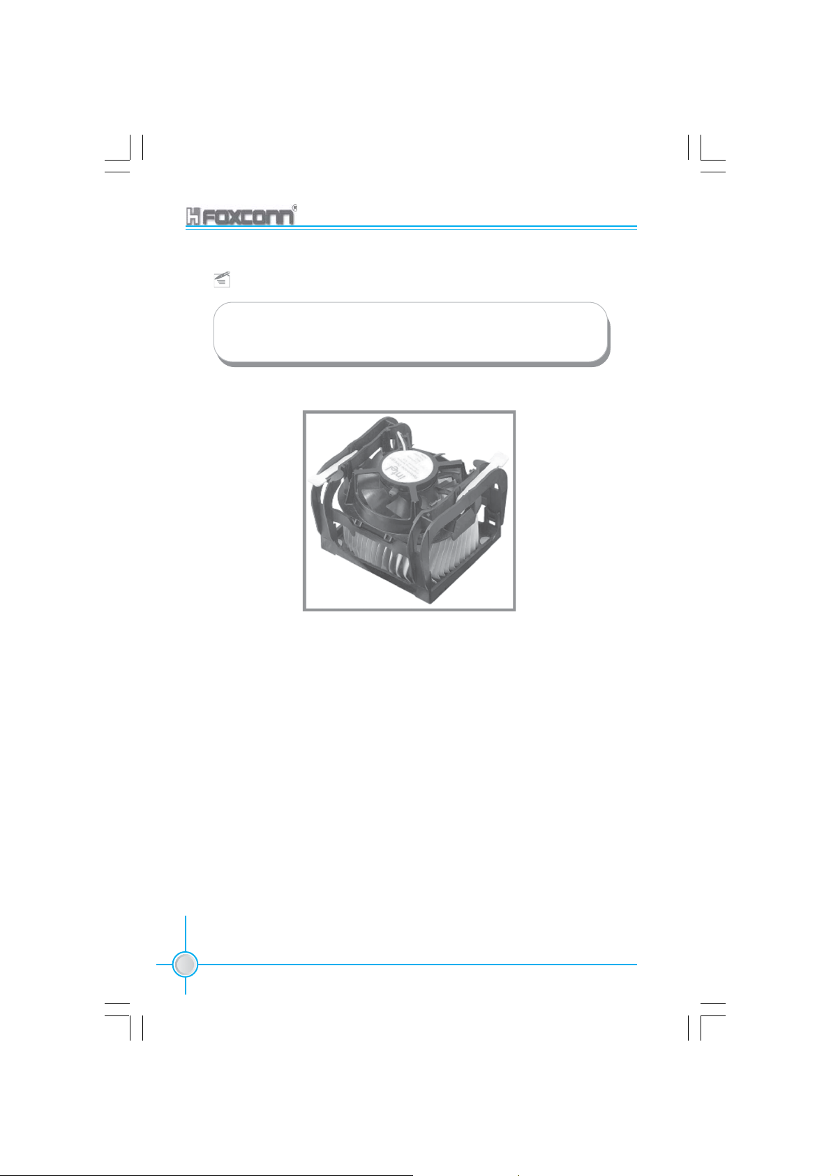
Installation of CPU Fan
New technology allows processors to run at higher and higher frequencies. To
avoid problems arising from high-speed operation, for example, overheating,
you need to install the proper fan. The following procedures are provided for
reference only, please refer your CPU fan user guide to install it.
1. Locate the CPU retention mecha-
nism base (surrounds the CPU
socket).
3. Attach the fan to the base.
2. If required, apply a light coating
of silica gel to the top of the CPU.
NOTE: The CPU heatsink may have a
pre-applied thermal compound. In that
case, the silica gel is not required.
4. Connect the power fan’s power
cable to the appropriate 3-pin
connector on the motherboard.
12
Note :
Excessive temperatures will severely damage the CPU and
system. Therefore, make sure that the cooling fan works normally
at all times in order to prevent overheating and damaging to the
CPU.
865M01G/PE/GV User Manual

Chapter 2 Installation Instructions
Attention:
1. Position the fan with the retention mechanism on top of the heatsink.
Align and snap the four hooks of the retention mechanism to the holes
on each corner of the module base.
2. Make sure that the fan and retention mechanism assembly perfectly fits
the headtsink and module base, otherwise you cannot snap the hooks
into the holes.
Retention Hole
Retention Lock
Retention Hook snapped to
the Retention Hole
Warning:
Keep the retention locks lifted upward while fitting the retention
mechanism to the module base.
865M01G/PE/GV User Manual
13
Chapter 2 Installation Instructions
Attention:
1. Push down the locks on the retention mechanism to secure the heatsink
and fan to the module base.
2. When secure,the retention locks should point to opposite directions.
14
865M01G/PE/GV User Manual

Chapter 2 Installation Instructions
CPU Qualified Vendor List
The following table lists the CPU modules that have been tested and
qualified for use with this motherboard.
Vendor Type FSB Frequency
Intel Pentium(Willamette) 400 1.7G,1.8G
Intel Celeron(Willamette) 400 1.7G,1.8G,
Intel Pentium(Northwood) 400 2.0G,2.2G,2.4G,2.5G,2.6G
Intel Celeron(Northwood) 400 2.0G,2.1G,2.2G,2.4G,2.6G
Intel Pentium(Northwood) 533 2.4G,2.53G,2.66G,2.8G,3.06G
Intel Pentium(Northwood) 800 2.4G,2.6G,2.8G,3.0G,3.2G
Intel Pentium(Prescott) 800 2.8G
Intel P4PXE(Northwood) 800 3.0G
865M01G/PE/GV User Manual
15

Chapter 2 Installation Instructions
Memory
This motherboard includes two 184-pin slots with 2.6V Double Data Rate (DDR)
Dual Inline Memory Module (DIMM) sockets, so you can install PC3200/2700/
2100 memory. You must install at least one memory bank to ensure normal
operation.
DIMM1
DIMM2
DDR Memory
The DDR SDRAM technology evolved from the mainstream PC66, PC100,
PC133 memory known as Single Data Rate (SDR) SDRAM. DDR memory,
however, has the ability to perform two data operations in one clock cycle,
thus providing twice the throughput of SDR memory.
A DDR DIMM has the same physical dimensions as an SDR DIMM, but it
has a 184-pin footprint compared to the 168-pin of the SDR DIMM. Also, a
DDR DIMM is single notched while an SDR DIMM is double notched.
Therefore, a DDR DIMM is not backward compatible with SDR, and should
be installed only in a socket specially designed for DDR DIMMs.
16
865M01G/PE/GV User Manual

Chapter 2 Installation Instructions
Memory configurations
You may install 64MB, 128MB, 256MB, 512MB and 1GB DDR DIMMs into the
DIMM sockets using the memory configurations in this section.
The following is important information on memory configurations:
1. Installing DDR DIMMs other than the recommended configurations may
cause memory sizing errors or system boot failures.
Note:
For dual-channel configuration, you may use only
identical DDR memorys in DIMM1 and DIMM2.
2. In dual-channel configurations, install only identical (the same type and size) DDR
DIMMs for each channel.
3. Always install DIMMs with the same CAS latency. For optimum compatibility, it is
recommended that you obtain memory modules from the same vendor. See the
following list of qualified vendors.
2100 memory modules that have been tested and qualified for use with this
motherboard.
The following table lists the PC3200/2700/
865M01G/PE/GV User Manual
17
Chapter 2 Installation Instructions
Vender Type Size
Infineon PC2100 (DDR 266) 256M
Infineon PC2700 (DDR 333) 128M,256M,512M
Infineon PC3200 (DDR 400) 256M,512M
Micron PC2100 (DDR 266) 128M,256M,512M
Micron PC2700 (DDR 333) 128M,256M,512M
Micron PC3200 (DDR 400) 256M
Samsung PC2100 (DDR 266) 256M
Samsung PC2700 (DDR 333) 256M,512M,1G
Samsung PC3200 (DDR 400) 256M,512M,1G
Kingmax PC2100 (DDR 266) 128M,256M
Kingmax PC2700 (DDR 333) 256M,512M
Kingmax PC3200 (DDR 400) 256M,512M
Kingston PC2100 (DDR 266) 128M,256M
Kingston PC2700 (DDR 333) 256M,512M
Kingston PC3200 (DDR 400) 256M,512M
Hynix PC2100 (DDR 266) 128M,256M
Hynix PC2700 (DDR 333) 256M,512M
Hynix PC3200 (DDR 400) 256M,512M
Transcend PC2100 (DDR 266) 256M
Transcend PC2700 (DDR 333) 256M,512M
Transcend PC3200 (DDR 400) 256M,512M
Apacer PC2100 (DDR 266) 256M
Apacer PC2700 (DDR 333) 256M,512M
Apacer PC3200 (DDR 400) 256M,512M
A-DATA PC2700 (DDR 333) 256M
A-DATA PC3200 (DDR 400) 256M
Nanya PC2100 (DDR 266) 128M,256M,512M
Nanya PC2700 (DDR 333) 128M,256M,512M
Winbond PC2700 (DDR 333) 256M,512M
TwinMos PC3200 (DDR 400) 256M,512M
Geil PC3200 (DDR 400) 256M
18
Note:
Make sure to use only the tested and qualified DDR DIMMS listed
above. Other DDR DIMMs manufactured by other vendors may not be
suitable for this motherboard.
865M01G/PE/GV User Manual

Chapter 2 Installation Instructions
4. Make sure that the memory frequency matches the CPU FSB (Front Side Bus). Refer
to the following table.
CPU FSB DDR DIMM Type Memory Frequency
800 MHz PC3200/PC2700/PC2100 400/333/266 MHz
533 MHz PC2700/PC2100 333/266 MHz
400 MHz PC2100 266 MHz
Note:
1. When using FSB 800MHz CPU,PC2700DDR DIMMs may
run only at 320MHz(not 333MHz) due to chipset limitation.
2. The following FSB/DDR ratios are not supported:400/333,
400/400,533/400.
5. When all two sockets are populated with 1GB DIMMs (total 2GB), the system may
detect over 1GB (a little less than 2GB) due to ICH5R resource allocation.
6. Double-sided DDR DIMMs with X16 (databus width=16-bit) memory chips are not
supported due to chipset limitations.
865M01G/PE/GV User Manual
19

Chapter 2 Installation Instructions
Installation of DDR Memory
1. There is only one gap in the center of the DIMM slot, and the memory module
can be fixed in one direction only. Unlock a DIMM slot by pressing the module
clips outward.
2. Align the memory module to the DIMM slot, and insert the module vertically
into the DIMM slot.
104 Pins 80 Pins
3. The plastic clips at both sides of the DIMM slot will lock automatically.
20
Warning :
Be sure to unplug the AC power supply before adding or remov-
ing expansion cards or other system peripherals, especially the
memory devices, otherwise your motherboard or the system
memory might be seriously damaged.
865M01G/PE/GV User Manual
Chapter 2 Installation Instructions
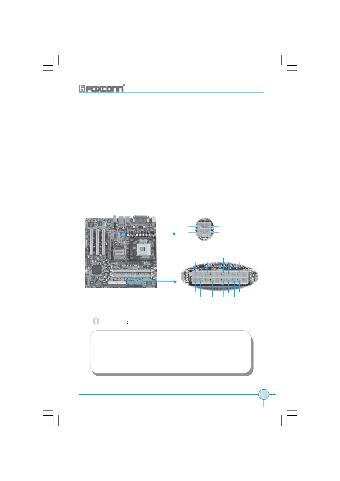
Power Supply
This motherboard uses an ATX power supply. In order to avoid damaging any
devices, make sure that they have been installed properly prior to connecting
the power supply.
20-pin ATX power connector: CN25
CN 25 is the ATX power supply connector. Make sure that the power supply cable
and pins are properly aligned with the connector on the motherboard. Firmly plug
the power supply cable into the connector and make sure it is secure.
4-pin ATX_12V Power Connector: CN11
The ATX power supply connects to CN11 and provides power to the CPU.
4-pin ATX_12V power connector
GND
12V
20
1
3
5V
2
GND
12V
4
20-pin ATX power connector
5V GND 3.3V GND GND
-5V GND PS-ON -12V
11
10
12V
Pw-OK 3.3V
5VSB
GND
5V
5V
GND 3.3V GND
Attention
You have to press the power button for more than four seconds if
you change the default “Instant-off” setting to “Delay 4 Sec” from
the “Soft-Off by PWR-BTTN” option in the BIOS Power Manage-
ment Setup.
865M01G/PE/GV User Manual
1
21

Chapter 2 Installation Instructions
Rear panel Connectors
This motherboard provides the ports as below:
PS/2 Mouse
1
Connector
PS/2 Keyboard
2
Connector
1
PS/2 Mouse Connector
Serial Port
3
(COM1)
SPP/EPP/ECP
4
Parallel Port
(Printer Port)
1394 Port
7
(Optional)
VGA Connector
5
(support on
865M01G/GV
only)
6
LAN Port
8
(Optional)
USB 2.0 Port
Line-in jack
Line-out jack
Microphone
jack
This green 6-pin connector is for a PS/2 Mouse.
2
PS/2 Keyboard Connector
This purple 6-pin connector is for a PS/2 keyboard.
3
Serial Port (COM1)
This 9-pin COM1 port is for pointing devices or other serial devices.
4
SPP/EPP/ECP Parallel Port (Printer Port)
This 25-pin port connects a parallel printer, a scanner, or other devices.
9
5
VGA Connector (support on 865M01G/GV only)
The VGA connector is for output to a VGA-compatible device.
6
USB 2.0 ports
These four Universal Serial Bus (USB) ports are available for connecting USB 2.0
devices.
7
1394 port (Optional)
This digital interface supports electronic devices such as digital cameras,
scanners, and printers.
22
865M01G/PE/GV User Manual
 Loading...